
NewsNEWCENTER
Featured products
Contact Us
GE 151X1207CK02SA02 De-Excitation Module Installation Guide
2026-09-30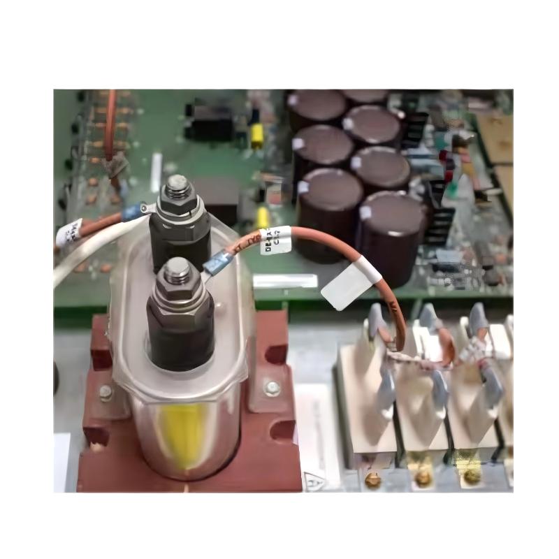
The GE 151X1207CK02SA02 De-Excitation Module is used in industrial excitation and generator control applications where controlled removal of excitation is required during shutdown, protection, or abnormal operating conditions. Proper installation requires careful attention to module identification, rack or panel mounting, control wiring, protection circuits, grounding, and commissioning. Because excitation systems can involve hazardous electrical energy, all installation and testing should be performed by qualified personnel following the equipment-specific electrical and safety procedures.
GE 151X1207CK02SA02 Module Overview
The GE 151X1207CK02SA02 functions as part of a generator excitation and protection system. A de-excitation circuit is responsible for rapidly removing or reducing excitation energy when the control system commands a shutdown or when a protective condition requires the generator field to be taken out of service.
In a typical control arrangement, the functional sequence can be represented as:
Generator Protection / Control Logic
              ↓29
      De-Excitation Command
              ↓
GE 151X1207CK02SA02 Module
              ↓
 De-Excitation Switching Circuit
              ↓
 Generator Excitation / Field Circuit
              ↓
 Controlled Removal of Excitation
The exact electrical architecture varies according to the excitation system in which the module is installed. Therefore, the 151X1207CK02SA02 should always be integrated according to the actual system drawings and approved wiring documentation.
Installation Preparation for GE 151X1207CK02SA02
Before installing the GE 151X1207CK02SA02, confirm the module identity and understand its position within the complete excitation system.
- Verify the complete part number: 151X1207CK02SA02.
- Inspect the module for physical damage or contamination.
- Confirm the intended rack, panel, or control-system position.
- Review the excitation-system electrical drawings.
- Identify the de-excitation command circuit.
- Identify associated field and protection circuits.
- Check grounding and shielding requirements.
- Verify all required isolation and discharge procedures.
- Confirm that test equipment is rated for the system being serviced.
Mounting and Mechanical Installation
Install the GE 151X1207CK02SA02 in its designated equipment location. The module should be mechanically secure and all associated connectors should be fully seated.
Do not force a connector into position. If mechanical engagement is difficult, inspect the connector, mounting position, and module orientation before applying pressure.
Cabinet Installation Considerations
- Provide adequate clearance for wiring and maintenance.
- Keep control wiring organized and clearly identified.
- Separate low-level control wiring from high-energy excitation conductors where applicable.
- Maintain cabinet grounding according to the plant electrical design.
- Prevent excessive heat, moisture, dust, and vibration from affecting the module.
151X1207CK02SA02 Wiring and System Integration
The exact terminal assignments and electrical connections for the GE 151X1207CK02SA02 must be verified against the applicable system drawings before wiring. Do not infer terminal functions from physical location or from another GE module.
The installation engineer should identify the following functional circuits:
- Control or de-excitation command input.
- Associated excitation control signals.
- Protection or trip interfaces.
- Power connections required by the module.
- Feedback or status circuits where applicable.
- Grounding connections.
Control wiring should be checked point-to-point before the excitation system is energized. Particular attention should be given to normally energized or normally de-energized protection logic because an incorrect contact arrangement can change the behavior of the de-excitation circuit.
GE 151X1207CK02SA02 Setup and Configuration
Unlike a conventional analog measurement module, a de-excitation module is normally evaluated as part of a larger protection and excitation sequence. Configuration therefore includes both the module installation and the logic controlling the de-excitation action.
- Verify the hardware location.
- Confirm all associated control connections.
- Verify the excitation-system logic.
- Check trip and protection interlocks.
- Confirm the expected normal and fault states.
- Verify feedback indications where provided.
- Review the shutdown sequence before commissioning.
GE 151X1207CK02SA02 Commissioning Procedure
Commissioning should begin with low-risk control verification before any full-energy excitation test is performed.
Mechanical Inspection
        ↓
Wiring Verification
        ↓
Control Power Verification
        ↓
Protection Logic Check
        ↓
De-Excitation Command Test
        ↓
Feedback / Status Verification
        ↓
Controlled Energized Test
        ↓
Final Protection Test
Control Circuit Test
Verify that the command signal reaches the appropriate interface and that the expected module response occurs. Where possible, perform the initial test under a controlled and isolated condition.
Protection Interlock Test
Check the protective conditions that are intended to initiate de-excitation. Each interlock should be verified according to the approved commissioning procedure.
Functional De-Excitation Test
A complete functional test should confirm that the de-excitation command produces the intended response in the excitation system. High-energy field tests must be performed only under approved plant procedures by qualified personnel.
Installation Validation Checklist
- Correct GE 151X1207CK02SA02 module installed.
- Module mechanically secure.
- Connectors correctly seated.
- Control wiring verified point-to-point.
- Protection interfaces verified.
- Grounding checked.
- Control logic reviewed.
- De-excitation command tested.
- Feedback indications verified.
- Complete shutdown response tested according to site procedure.
Representative Commissioning Case
Consider a representative generator control installation where the excitation system does not respond correctly when the de-excitation command is initiated during commissioning. The technician first checks the control logic and confirms that the command is being generated. The next step is to verify the command path toward the de-excitation module.
A point-to-point wiring inspection identifies an incorrect control connection. After correcting the wiring and repeating the controlled test, the module responds correctly and the expected de-excitation sequence is observed.
This example demonstrates why excitation-system commissioning should verify the entire control chain rather than assuming that a non-responsive system automatically indicates a failed module.
151X1207CK02SA02 Installation FAQs
What is the GE 151X1207CK02SA02 used for?
The GE 151X1207CK02SA02 is a de-excitation module used as part of an excitation and generator protection system to support controlled removal of excitation.
Can the module be wired using another GE module as a reference?
The physical appearance of modules should not be used as a substitute for the correct wiring documentation. Verify every terminal and interface against the applicable system drawings.
Why is de-excitation important in a generator system?
De-excitation provides a controlled method of removing generator field excitation during shutdown and specified protective conditions.
What should be checked before an energized commissioning test?
Verify mechanical installation, control wiring, protection logic, grounding, interlocks, command behavior, and approved safety procedures before applying hazardous excitation energy.
Technical Summary
Correct installation of the GE 151X1207CK02SA02 De-Excitation Module depends on accurate system identification, secure mechanical installation, verified control wiring, correct protection logic, and controlled commissioning. Because the module operates within an excitation and protection environment, successful installation should always be evaluated as part of the complete generator control sequence rather than as an isolated hardware task.