

ProductPRODUCT
Featured products
Contact Us
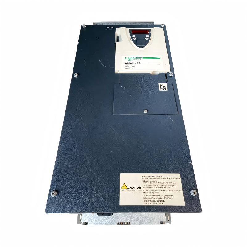
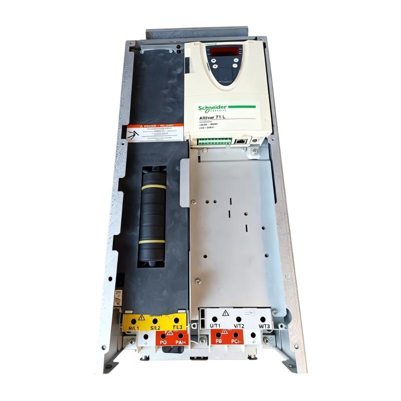
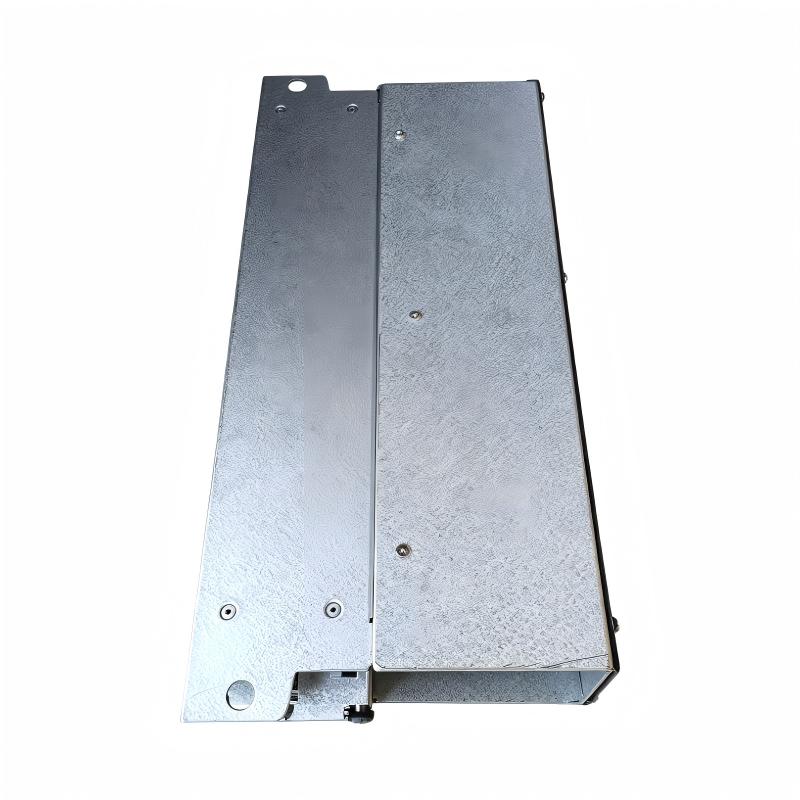
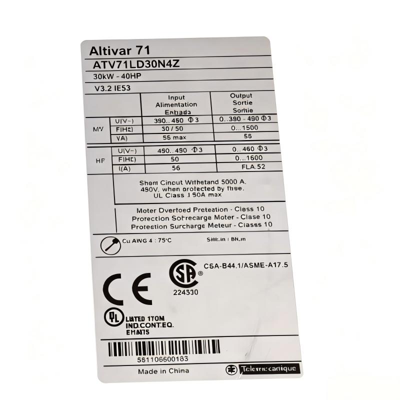
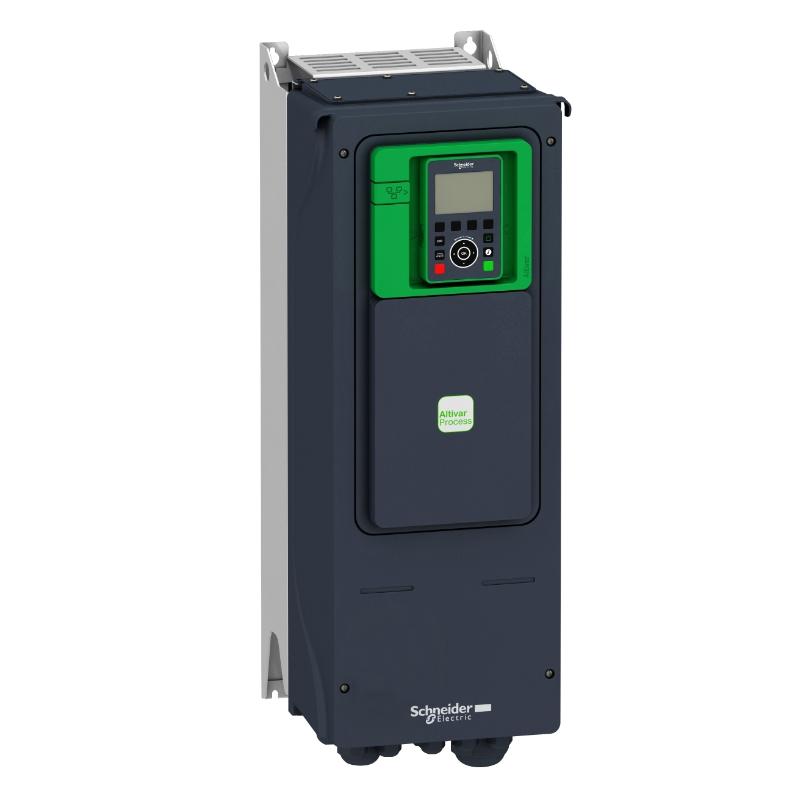
- Schneider
- ATV71LD30N4Z
- Variable Speed Drive
- France
- 240 × 550 × 240 mm
- 37.2 kg
- Xiamen, China
- New & In Stock
- T/T, PayPal, Western Union
- 1 Year
- 1-3 Working Days
- DHL, UPS, TNT, FedEx and EMS.
- 24-Hour Service
- COO
- 3
Our advantage

Global Logistics
We have a 10-year logistics and express cooperation agreement, so our products can be shipped to any place in the world.

Brand new and original
Our products are imported in bulk from the place of origin. Because of the cooperative relationship, our products are all original and 100% new.

24-hour service
We provide 7*24 hours service to our customers. We will be there whenever you need us.

Price advantage
All our products are priced very favorably because we have our own warehouse and supply.
| Company Information | |||
| [email protected] | |||
| Mobile | +8615980777398 | ||
| +8615980777398 | |||
| 15980777398 |
Product Overview
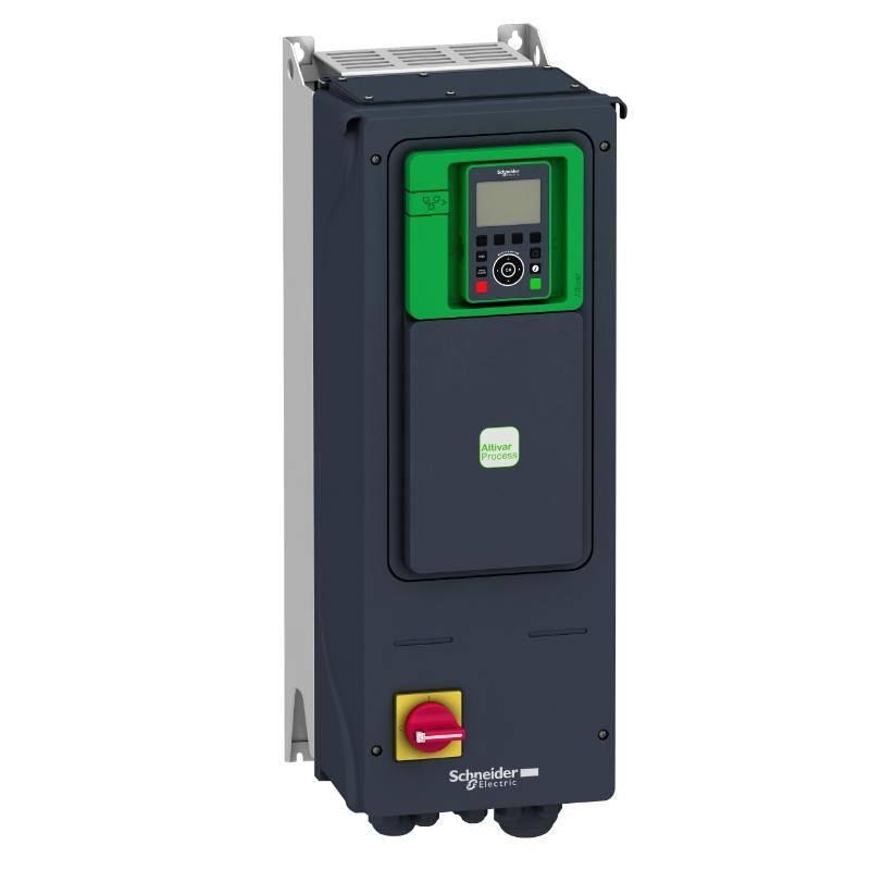
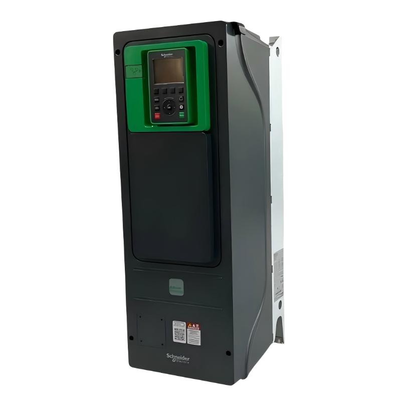
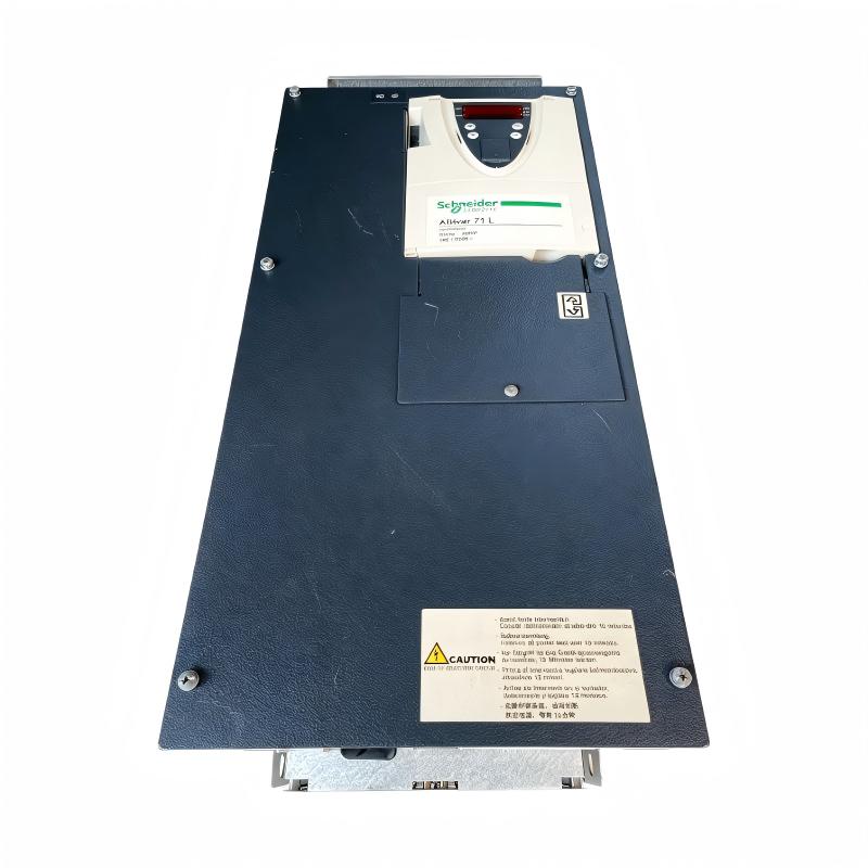
The Schneider ATV71LD30N4Z Variable Speed Drive is an industrial motor control device designed for applications requiring controlled speed, acceleration, deceleration, and torque management of AC motors. As part of the Schneider Electric Altivar 71 family, the ATV71LD30N4Z is intended for demanding industrial automation environments where reliable variable-speed motor operation is required.
Variable speed drives are widely used to control motors in machinery and process equipment. Instead of operating a motor continuously at a fixed speed, a drive regulates the electrical output supplied to the motor so that motor operation can be adapted to the actual requirements of the application. This can improve process control, reduce unnecessary mechanical stress, and provide greater flexibility during machine operation.
The ATV71LD30N4Z is identified as a 30 kW-class Altivar 71 drive model. The user-supplied physical specifications for this model are 240 × 550 × 240 mm and 37.2 kg. These dimensions and weight should be considered when planning cabinet installation, transportation, replacement, and maintenance access.
The drive can be incorporated into industrial control architectures together with PLCs, HMIs, sensors, contactors, motor protection equipment, communication networks, and other automation components. Its role is primarily to provide controlled electrical power and motor-speed management between the incoming power system and the connected motor.
Technical Specifications
| Parameter | Specification |
|---|---|
| Manufacturer | Schneider Electric |
| Model | ATV71LD30N4Z |
| Product Family | Altivar 71 |
| Product Type | Variable Speed Drive |
| Drive Category | AC Motor Drive / Variable Frequency Drive |
| Motor Power Class | 30 kW |
| Application | Industrial Motor Speed Control |
| Dimensions (H × W × D) | 240 × 550 × 240 mm |
| Weight | 37.2 kg |
| Mounting | Industrial cabinet or equipment installation |
| Motor Control | Variable-speed AC motor control |
| Typical System | PLC / HMI / Drive / Motor automation system |
| Typical Applications | Pumps, fans, conveyors, machinery, compressors, process equipment |
Note: The dimensions and weight above are based on the supplied product information. Exact electrical ratings, current values, overload characteristics, communication options, terminals, and configuration parameters should be verified against the specific ATV71LD30N4Z hardware and application before installation.
Understanding the Schneider ATV71LD30N4Z
The ATV71LD30N4Z is a variable speed drive used to regulate the operation of an AC motor. In a conventional fixed-speed motor installation, the motor is generally connected to the power supply through switching and protection equipment and operates at a speed determined largely by the supply frequency and motor characteristics.
A variable speed drive introduces an electronic control stage between the electrical supply and motor.
A simplified system can be represented as:
AC Power Supply → ATV71LD30N4Z → AC Motor → Mechanical Load
The drive receives electrical power and generates a controlled output for the motor. The controller can modify operating conditions according to the required speed, acceleration, deceleration, torque, or process demand.
In an automated machine, the drive may also receive commands from a PLC or other controller. Feedback from sensors can be used by the overall control system to determine how the motor should operate.
This arrangement allows the motor to become an integrated part of the automation system rather than functioning as an isolated electrical device.
Variable Speed Drive Operating Principle
The basic operating principle of a variable speed drive is based on controlling the electrical characteristics supplied to the motor.
The drive performs several important stages of operation.
AC Input
Electrical power enters the drive from the industrial power system. Appropriate upstream protection and disconnect equipment should be provided according to the system design.
Power Conversion
The drive converts the incoming electrical power through its internal power electronics. The resulting electrical output can be controlled according to the motor operating requirements.
Motor Control
The drive regulates the output supplied to the motor. By changing the output conditions, the motor can accelerate, decelerate, or operate at a commanded speed.
Process Control
The drive can operate according to local commands, external control signals, or commands transmitted through an automation system.
This makes the ATV71LD30N4Z suitable for applications where motor speed must change according to production conditions.
Major Functions of the ATV71LD30N4Z
The main purpose of the ATV71LD30N4Z is controlled motor operation. Depending on the overall system configuration, a variable speed drive can perform several important functions.
Adjustable Motor Speed
The drive allows motor operation to be adjusted rather than limiting the machine to a single fixed operating point.
Controlled Acceleration
Acceleration can be controlled to reduce sudden mechanical loading on the motor and connected machinery.
Controlled Deceleration
Controlled deceleration can help reduce mechanical shock and improve the stopping behavior of industrial equipment.
Process Optimization
Motor speed can be matched more closely to the actual process requirement.
Motor Protection Functions
Drive-based monitoring can help identify abnormal electrical or operating conditions. Exact protection functions depend on the drive configuration and application.
Automation Integration
The drive can form part of a larger industrial automation system containing PLCs, HMIs, sensors, and supervisory equipment.
Role in Industrial Automation
The ATV71LD30N4Z can function as an important layer between machine-control logic and physical motor equipment.
A typical industrial control architecture may contain:
PLC → Control Command → Variable Speed Drive → Motor → Mechanical Equipment
The PLC determines what the machine should do. The drive translates the required operating command into controlled motor operation.
For example, a PLC may determine that a conveyor needs to operate at a particular speed. The corresponding command is sent to the drive, which regulates the motor accordingly.
In a pump application, process information such as pressure or flow may be used by the control system to determine the required motor speed.
This division of responsibilities allows the PLC to concentrate on control logic while the drive manages motor-related electrical control.
Industrial Applications
The ATV71LD30N4Z can be considered for a wide range of industrial motor-control applications where variable-speed operation is required.
Conveyor Systems
Conveyors frequently require controlled acceleration and adjustable operating speed. A variable speed drive allows the conveyor speed to be coordinated with upstream and downstream equipment.
Pumps
Industrial pumps may require different operating speeds according to process demand. Variable-speed control can help the pump operate according to changing system requirements.
Fans and Blowers
Ventilation and process-air systems can benefit from adjustable motor speed, particularly when airflow requirements change during operation.
Compressors
Industrial compressors may use variable-speed control as part of a larger process-management strategy. The drive can regulate motor operation according to the control system’s requirements.
Material Handling Machinery
Hoists, conveyors, feeders, and other material-handling equipment can require controlled acceleration and deceleration to reduce mechanical stress.
Manufacturing Equipment
Production machinery may use variable-speed motors for cutting, feeding, winding, mixing, or other machine processes.
Process Automation
Industrial processes often require motor speed to change according to temperature, pressure, flow, level, or production conditions. A variable speed drive provides the motor-control layer needed for these applications.
Installation and Cabinet Integration
Correct mechanical and electrical installation is essential for reliable operation of the ATV71LD30N4Z.
Because the supplied product weight is 37.2 kg, the mounting structure should be capable of securely supporting the drive and any associated mechanical forces during installation and service.
Cabinet Planning
Before installation, engineers should verify:
- Available cabinet space
- Mounting arrangement
- Cable entry locations
- Ventilation requirements
- Maintenance access
- Clearance around the drive
- Upstream protection equipment
- Motor cable routing
- Control wiring arrangement
The supplied dimensions are:
240 × 550 × 240 mm
These dimensions should be incorporated into the cabinet layout before mechanical fabrication.
Vertical Installation
The drive should normally be mounted according to the manufacturer’s approved installation orientation. Correct positioning is important because the drive’s thermal performance depends on appropriate airflow and heat dissipation.
Cable Routing
Power cables and low-level control or communication cables should be routed appropriately to reduce the possibility of electrical interference.
Motor cables should also be selected and installed according to the application and applicable electrical requirements.
Electrical Integration
A typical drive installation contains several functional sections.
Incoming Power
The incoming power circuit supplies the drive. Appropriate disconnect and protection equipment should be installed according to the system design.
Drive
The ATV71LD30N4Z performs the variable-speed motor-control function.
Motor Cable
The motor cable transfers the controlled output from the drive to the AC motor.
Motor
The motor converts electrical energy into mechanical energy.
Control System
A PLC, HMI, or other controller can provide commands and receive operational information from the drive.
A simplified arrangement is:
Power System → Protection → ATV71LD30N4Z → Motor
with a parallel control path:
PLC / HMI → Drive Control Interface
The exact wiring depends on the machine design and selected control method.
PLC and HMI Integration
The ATV71LD30N4Z can be incorporated into an automated machine in which a PLC controls the motor operating sequence.
A typical sequence may be:
- PLC verifies machine safety conditions.
- Drive receives an enable or operating command.
- The required motor speed is established.
- Drive accelerates the motor.
- Motor drives the connected machine.
- Sensors provide process information.
- PLC adjusts the motor command when process conditions change.
- Drive decelerates or stops the motor when required.
An HMI can provide operators with information such as operating status, commanded speed, fault conditions, and maintenance information depending on the implemented system.
Commissioning Procedure
Commissioning should be performed systematically rather than simply applying power and starting the motor.
Step 1: Verify the Model
Confirm that the installed drive is the correct ATV71LD30N4Z model for the intended application.
Step 2: Inspect the Installation
Check the mounting, cabinet arrangement, connectors, cable routing, grounding, and physical condition of the drive.
Step 3: Verify Motor Information
Enter or confirm the motor data required by the drive configuration. Incorrect motor parameters can result in poor motor performance or unexpected drive behavior.
Step 4: Check Command Sources
Determine whether the drive will receive commands locally, through external terminals, or from a supervisory controller.
Step 5: Verify Speed References
Confirm the source and scaling of the speed reference.
Step 6: Test at Low Operating Conditions
Where appropriate, perform an initial controlled test before allowing the machine to operate at full process conditions.
Step 7: Check Rotation
Verify that the motor rotates in the correct direction.
Step 8: Verify Acceleration and Deceleration
Observe the motor during starting and stopping and confirm that the mechanical system responds correctly.
Step 9: Test the Automation Sequence
Confirm that PLC commands, interlocks, alarms, and operator controls function correctly.
Troubleshooting the ATV71LD30N4Z
When a variable speed drive does not operate correctly, troubleshooting should consider the complete system rather than assuming that the drive itself is defective.
Drive Does Not Start
Possible areas to inspect include:
- Incoming power
- Drive enable command
- Control wiring
- Start/stop command
- Speed reference
- Active fault condition
- Safety interlocks
- PLC sequence
- Motor connection
The first step should be to determine whether the drive is receiving a valid operating command.
Motor Does Not Accelerate
If the drive is enabled but the motor does not accelerate normally, check the programmed speed reference, motor parameters, mechanical load, and active drive status.
An excessive mechanical load can also prevent the motor from reaching the expected speed.
Motor Stops Unexpectedly
Unexpected stopping can be associated with a drive protection event, loss of command, control-system interlock, motor-side problem, or process condition.
The drive fault or status information should be reviewed before replacing hardware.
Excessive Motor Current
High motor current may be associated with:
- Excessive mechanical load
- Incorrect motor configuration
- Mechanical obstruction
- Motor problems
- Acceleration settings
- Incorrect application parameters
- Electrical connection issues
The mechanical system should be inspected together with the electrical system.
Unstable Motor Operation
Unstable operation may result from incorrect control parameters, unstable reference signals, mechanical load variation, electrical interference, or feedback-related problems in applications using feedback control.
Preventive Maintenance
Regular maintenance can help reduce unexpected drive downtime.
Visual Inspection
Inspect the drive for:
- Dust accumulation
- Signs of overheating
- Damaged wiring
- Loose connections
- Physical damage
- Unusual discoloration
- Foreign material
Cabinet Environment
The control cabinet should be maintained within the environmental conditions specified for the equipment.
Excessive heat, dust, humidity, and vibration can shorten the service life of electronic equipment.
Cable Inspection
Power, motor, control, and communication cables should be inspected periodically.
Connection Inspection
Loose electrical connections can create heat and unstable operation. Connections should be checked as part of an appropriate maintenance program.
Fault History
Where available, drive fault and event information should be reviewed periodically. Repeated faults may indicate an underlying mechanical or electrical problem rather than an isolated drive failure.
Replacement Considerations
When replacing an ATV71LD30N4Z, the complete model number should be checked rather than relying only on physical appearance.
Important details include:
- Full drive reference
- Product family
- Motor power class
- Input power requirements
- Application requirements
- Control configuration
- Communication arrangement
- Motor characteristics
- Mounting dimensions
- Wiring configuration
- Existing parameter settings
The physical specifications supplied for this model are:
Dimensions: 240 × 550 × 240 mm
Weight: 37.2 kg
The replacement drive should also be evaluated for cabinet space, cable routing, heat dissipation, and maintenance accessibility.
A drive with a similar appearance should not automatically be considered an interchangeable replacement.
Related System Components
A complete variable-speed motor system can include multiple components surrounding the ATV71LD30N4Z.
| Component | Typical Function |
|---|---|
| ATV71LD30N4Z | Variable-speed motor control |
| AC Motor | Converts electrical power into mechanical motion |
| PLC | Executes machine-control logic |
| HMI | Operator monitoring and control |
| Circuit Protection | Protects the incoming electrical circuit |
| Disconnect Device | Provides equipment isolation |
| Motor Cable | Transfers controlled power to the motor |
| Sensors | Provide process or machine feedback |
| Communication Network | Exchanges control and status information |
| Mechanical Load | Performs the required industrial operation |
The exact combination depends on the machine architecture.
Physical Dimensions and Handling
The Schneider ATV71LD30N4Z has user-supplied dimensions of:
240 × 550 × 240 mm
Its listed weight is:
37.2 kg
The relatively substantial weight should be considered during transportation, cabinet installation, removal, and maintenance.
For installation planning, engineers should account for more than the physical envelope of the drive. Cable bending radius, terminal access, ventilation space, service access, and adjacent equipment must also be considered.
When removing a drive from an operating cabinet, appropriate lifting and handling procedures should be used for the 37.2 kg assembly.
Engineering Best Practices
Several engineering practices can improve the reliability of an ATV71LD30N4Z installation.
Match the Drive to the Motor
The drive should be selected according to the motor’s electrical characteristics and the application’s load requirements.
Separate Power and Control Wiring
Where practical, keep high-power motor wiring separated from sensitive control and communication circuits.
Document Parameters
Important drive configuration parameters should be documented so that they can be restored after replacement.
Record the Existing Installation
Before replacing a drive, record wiring, terminal assignments, control sources, motor information, and operating parameters.
Verify Mechanical Load
Drive sizing should consider not only motor power but also acceleration requirements, load inertia, duty cycle, braking requirements, and process conditions.
Maintain Cabinet Conditions
Good thermal management and appropriate cabinet cleanliness are important for electronic drive reliability.
Key Advantages
The Schneider ATV71LD30N4Z provides several practical advantages for industrial motor-control applications:
- Variable-speed control for AC motors
- Suitable for demanding industrial automation environments
- Controlled acceleration and deceleration
- Integration into PLC-based automation systems
- Flexible application-oriented motor control
- Supports centralized machine control architectures
- Useful for pumps, fans, conveyors, compressors, and machinery
- Compact physical envelope relative to its industrial power class
- Suitable for cabinet-based industrial installations
- Supports systematic motor monitoring and troubleshooting
Technical FAQs
What is the Schneider ATV71LD30N4Z?
The Schneider ATV71LD30N4Z is an Altivar 71 Variable Speed Drive designed for industrial AC motor control applications.
What motor power class is associated with the ATV71LD30N4Z?
The model is identified as a 30 kW-class variable speed drive.
What are the dimensions of the ATV71LD30N4Z?
The supplied dimensions are 240 × 550 × 240 mm.
How much does the ATV71LD30N4Z weigh?
The supplied product weight is 37.2 kg.
What is the main function of the ATV71LD30N4Z?
Its primary function is to regulate the operation of an AC motor by controlling motor speed and operating conditions according to the requirements of the industrial application.
Can the ATV71LD30N4Z be used with a PLC?
Yes, a variable speed drive can be integrated into a PLC-based automation system. The exact control interface and communication arrangement depend on the system configuration.
What applications can use the ATV71LD30N4Z?
Typical applications include industrial conveyors, pumps, fans, compressors, material-handling equipment, manufacturing machinery, and process-control systems.
What should be checked before replacing an ATV71LD30N4Z?
The complete model number, motor requirements, input power, control configuration, wiring, mounting dimensions, communication arrangement, and application requirements should be verified before replacement.
Why is drive commissioning important?
Proper commissioning confirms that the motor parameters, command sources, speed references, rotation direction, acceleration, deceleration, safety conditions, and automation sequence are correctly configured.
What can cause a drive-controlled motor to stop unexpectedly?
Possible causes include active drive protection, loss of a start command, PLC interlocks, motor problems, excessive load, control wiring problems, or abnormal process conditions. The complete system should be inspected before determining the cause.
Conclusion
The Schneider ATV71LD30N4Z Variable Speed Drive is an industrial AC motor-control solution designed to provide adjustable motor operation within automated machinery and process systems. As part of the Altivar 71 family, it can serve as the electrical interface between an industrial power system and a controlled AC motor, while also fitting into larger PLC, HMI, sensor, and process-control architectures.
The supplied physical specifications for the ATV71LD30N4Z are 240 × 550 × 240 mm with a weight of 37.2 kg. These values are important for cabinet design, transportation, installation, replacement planning, and maintenance access.
For reliable operation, engineers should treat the drive as one part of a complete motor-control system. Correct motor configuration, appropriate electrical protection, suitable cable installation, proper cabinet ventilation, accurate control parameters, and systematic commissioning all contribute to stable operation.
Whether installed in a conveyor, pump, fan, compressor, manufacturing machine, or other industrial application, the ATV71LD30N4Z can provide the variable-speed control required to coordinate motor performance with changing process demands. Before installation or replacement, the complete model designation and application-specific electrical characteristics should always be verified against the actual equipment configuration.