

ProductPRODUCT
Featured products
Contact Us
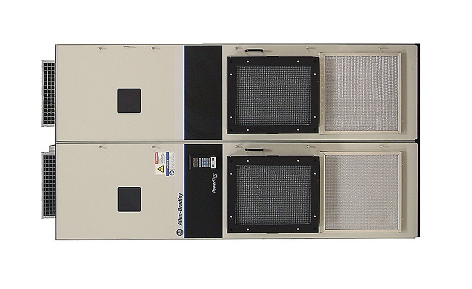
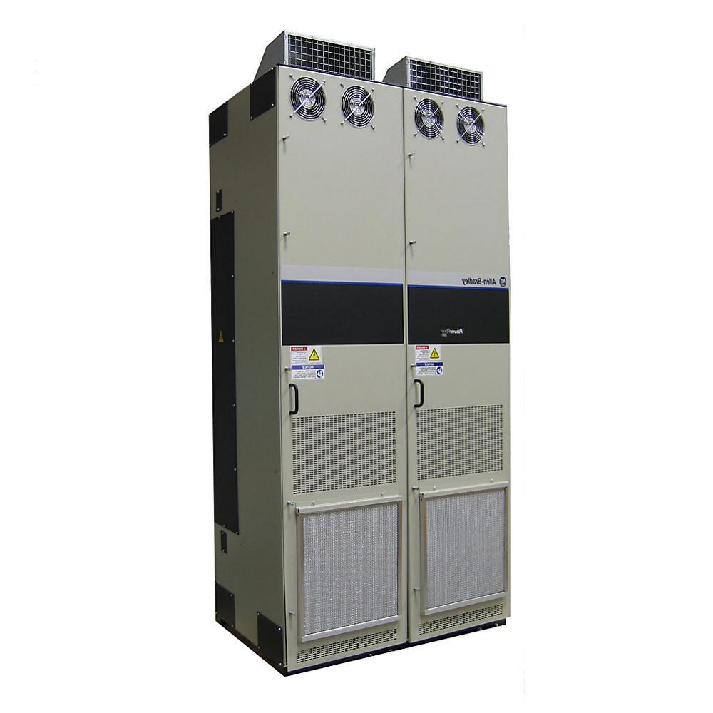
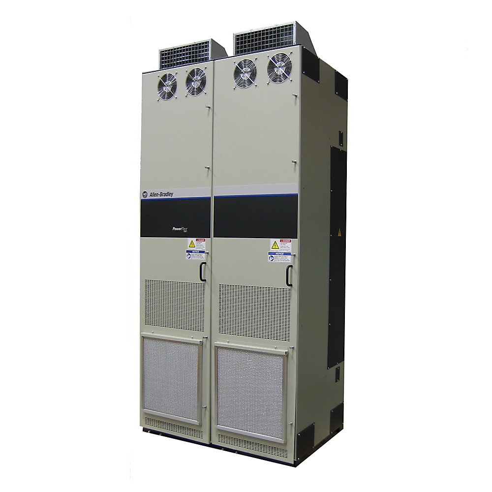
- Allen Bradley
- 20J1F3F1K8LNDNNNNN
- PowerFlex AC Drive
- USA
- 2477 × 1200 × 800 mm
- 650kg
- Xiamen, China
- New & In Stock
- T/T, PayPal, Western Union
- 1 Year
- 1-3 Working Days
- DHL, UPS, TNT, FedEx and EMS.
- 24-Hour Service
- COO
- 4
Our advantage

Global Logistics
We have a 10-year logistics and express cooperation agreement, so our products can be shipped to any place in the world.

Brand new and original
Our products are imported in bulk from the place of origin. Because of the cooperative relationship, our products are all original and 100% new.

24-hour service
We provide 7*24 hours service to our customers. We will be there whenever you need us.

Price advantage
All our products are priced very favorably because we have our own warehouse and supply.
| Company Information | |||
| [email protected] | |||
| Mobile | +8615980777398 | ||
| +8615980777398 | |||
| 15980777398 |
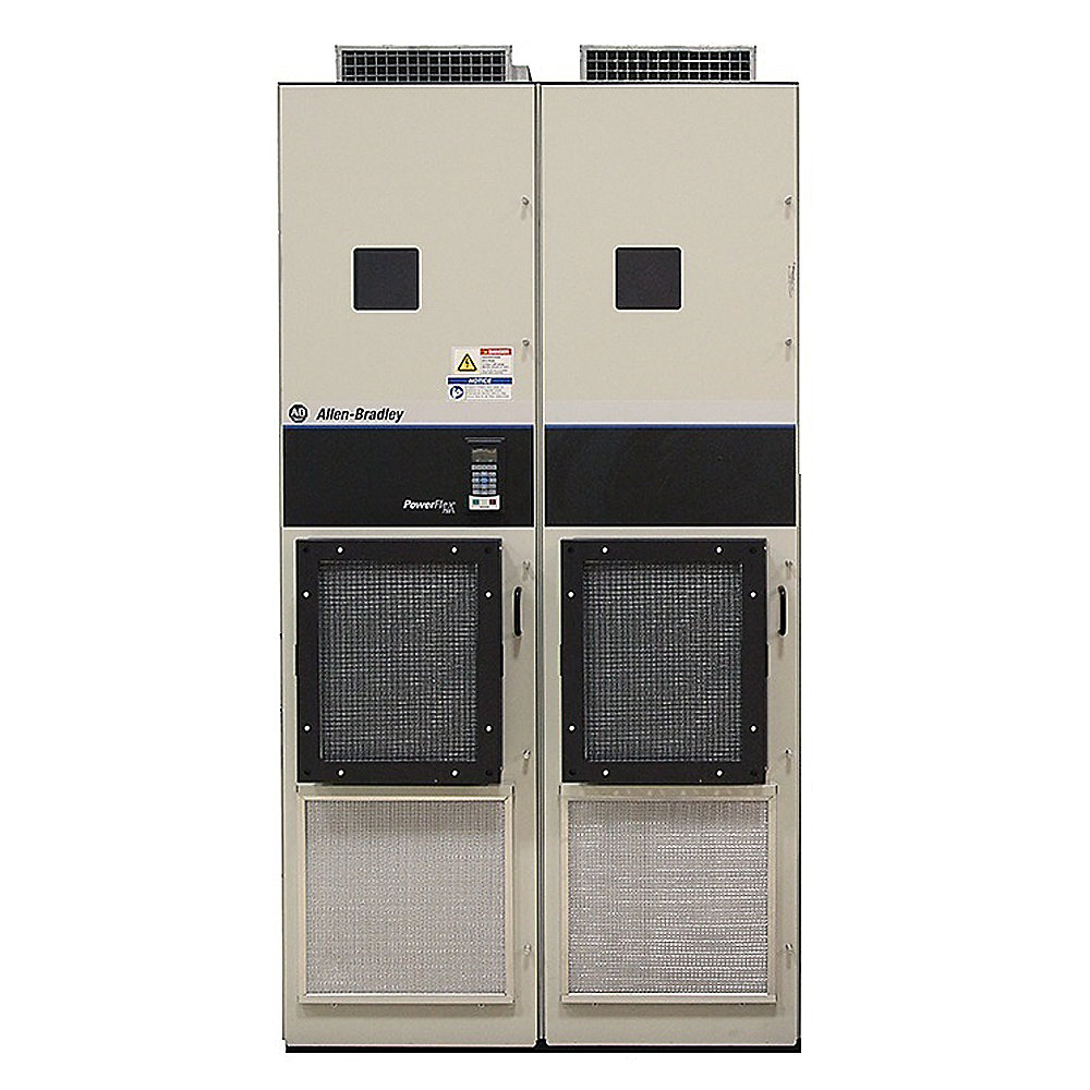
Allen-Bradley 20J1F3F1K8LNDNNNNN PowerFlex 755TM 690V AFE Bus Supply
Product Overview
The Allen-Bradley 20J1F3F1K8LNDNNNNN is a high-power PowerFlex 755TM bus supply designed for large industrial drive systems that use a common DC bus architecture.
This model belongs to the high-power 690 V AC class and uses an active front-end arrangement for regenerative and low-harmonic operation. With a Normal Duty rating of approximately 1,914 kW, it is intended for large electrical systems where several motor inverters or drive sections need to share a centralized DC bus.
The unit is considerably different from a conventional standalone variable-frequency drive. Instead of directly controlling one motor, a bus supply converts incoming three-phase AC power into a controlled DC bus supply that can be distributed to multiple compatible inverter sections.
This type of architecture is useful when a plant contains several large motors, especially where centralized power distribution, regenerative energy handling, and coordinated drive operation are important.
The catalog number 20J1F3F1K8LNDNNNNN identifies a particular configuration within the PowerFlex 755TM bus-supply family. The final catalog-number positions represent configuration and option selections, so the exact installed hardware should always be checked against the unit nameplate when preparing a replacement or engineering a system.
Basic Product Information
| Parameter | Specification |
|---|---|
| Model | 20J1F3F1K8LNDNNNNN |
| Brand | Allen-Bradley |
| Product Family | PowerFlex 755T |
| Product Series | PowerFlex 755TM |
| Product Type | Regenerative / AFE Bus Supply |
| Drive Function | Common DC Bus Supply |
| Input Voltage Class | 690 V AC |
| Input Phase | 3 Phase |
| DC Bus Output Class | 1000 V DC |
| Normal Duty Power | Approximately 1,914 kW |
| Normal Duty Continuous DC Output Current | Approximately 1,914 A |
| Frame Size | Frame 11 |
| Cooling | Forced Air |
| Enclosure Class | IP21 / UL Type 1 class |
| Mounting | Floor Mount |
| Regenerative Capability | Yes |
| Active Front End | Yes |
| Low-Harmonic Architecture | Yes |
| Common DC Bus | Yes |
| Installation Type | Large industrial cabinet system |
| Application Level | Heavy industrial / high-power process equipment |
| Typical System Architecture | Centralized AC-to-DC bus with multiple inverters |
The 1,914 kW figure is the Normal Duty rating associated with the 690 V F1K8 rating. The corresponding Frame 11 bus-supply configuration is rated at approximately 1,914 A on the DC side.
Product Series
PowerFlex 755TM
The PowerFlex 755TM series is designed around common DC bus applications.
Instead of installing a separate complete AC input section for every motor inverter, the system can use a centralized bus supply and then distribute DC power to multiple inverter sections.
For large machinery, this can make the overall electrical architecture more organized. It can also make regenerative energy management easier when several motors operate together.
The PowerFlex 755TM platform covers a wide range of power levels and frame sizes, from comparatively smaller industrial installations through very large multi-megawatt systems.
The 20J catalog prefix identifies the bus-supply portion of the PowerFlex 755TM architecture.
The F voltage designation corresponds to the 690 V AC class.
The F1K8 rating identifies the high-power Frame 11 class used by this model.
Catalog Number Structure
The catalog number can be read as a configuration identifier rather than simply a model name.
| Catalog Position / Code | Meaning |
|---|---|
| 20J | PowerFlex 755TM bus supply |
| 1 | Cooling / configuration designation |
| F | 690 V AC class |
| 3 | IP21 / UL Type 1 floor-mounted enclosure class |
| F1K8 | 690 V high-power rating, Frame 11 |
| L | EMI/filtering configuration |
| N | Option position |
| D | Option/configuration designation |
| NNNNN | Additional configuration positions |
The catalog number should not be interpreted by changing one character at a time without checking the complete configuration. For large PowerFlex 755TM systems, enclosure, filtering, control, precharge, bus arrangement, and other options can affect the final equipment configuration.
Detailed Technical Specifications
| Parameter | 20J1F3F1K8LNDNNNNN |
|---|---|
| Model | 20J1F3F1K8LNDNNNNN |
| Brand | Allen-Bradley |
| Series | PowerFlex 755TM |
| Product Category | Bus Supply |
| Input Voltage | 690 V AC nominal class |
| Input Frequency | 50 Hz class |
| Input Phase | 3 Phase |
| DC Output Voltage | Up to approximately 1000 V DC class |
| Normal Duty Rating | 1,914 kW |
| Normal Duty DC Current | 1,914 A |
| Heavy Duty Rating | Approximately 1,500 kW |
| Heavy Duty DC Current | Approximately 1,576 A |
| Frame | 11 |
| Cooling Method | Forced Air |
| Enclosure | IP21 / UL Type 1 class |
| Installation | Floor standing |
| Power Conversion | Active Front End |
| Regeneration | Supported |
| Harmonic Reduction | Active front-end / low-harmonic architecture |
| Common DC Bus | Supported |
| Motor Control | Performed by downstream inverter sections |
| Typical System | Multi-drive common DC bus |
| Approximate Heat Dissipation | About 51.6 kW at the referenced light-duty operating condition |
| Typical Environment | Clean industrial indoor electrical room |
| Mounting Orientation | Vertical floor-mounted cabinet |
| Service Requirement | Industrial high-voltage maintenance procedures |
| Typical Power Level | Approximately 1.9 MW |
| Approximate Weight | About 1,300–1,600 kg class, configuration dependent |
| Approximate Cabinet Width | About 2,600 mm class |
| Approximate Cabinet Depth | About 600 mm class |
| Approximate Cabinet Height | About 2,000 mm class |
The dimensions and weight above should be treated as planning-level approximate values, rather than shipment-certified dimensions. Large PowerFlex 755TM equipment is assembled from multiple sections, and the actual overall width and shipping weight can change according to wire bays, enclosure options, control arrangements, bus configuration and other selected hardware.
Electrical Characteristics
The 20J1F3F1K8LNDNNNNN is designed for a 690 V AC three-phase industrial supply.
Its F1K8 rating corresponds to a Frame 11 bus-supply configuration. At Normal Duty, the DC output rating is approximately 1,914 kW / 1,914 A.
The DC side operates in the approximately 1000 V DC class, which makes this equipment suitable for very high-power common-bus drive installations.
| Electrical Parameter | Approximate Value |
|---|---|
| Model | 20J1F3F1K8LNDNNNNN |
| AC Input Voltage | 690 V AC |
| AC Input | 3 Phase |
| AC Frequency | 50 Hz class |
| DC Output Voltage | 1000 V DC class |
| Normal Duty DC Power | 1,914 kW |
| Normal Duty DC Current | 1,914 A |
| Heavy Duty DC Power | 1,500 kW |
| Heavy Duty DC Current | 1,576 A |
| Internal DC Bus Capacitance | Approximately 31,000 µF |
| Maximum External DC Bus Capacitance | Approximately 137,134 µF |
| Power Conversion | Active Front End |
| Regeneration | Available |
| Line-Side Conversion | Active controlled rectification |
| DC Bus Application | Multiple inverter sections |
The large current rating is one of the most important characteristics of this product. At this power level, cable selection, busbar design, short-circuit protection, grounding, thermal management and mechanical installation become major engineering considerations.
Active Front End and Regenerative Operation
One of the main characteristics of the PowerFlex 755TM bus-supply architecture is its Active Front End, commonly abbreviated as AFE.
A conventional diode rectifier generally converts AC into DC in one direction. An AFE can actively control the power exchange between the AC system and the DC bus.
That becomes particularly useful when the connected motors operate in regenerative conditions.
For example, a large hoist may lower a heavy load. During that period, the motor can act as a generator. The regenerated energy can be transferred back through the common DC bus and, where the system configuration permits, returned to the AC supply rather than being dissipated entirely as heat.
The same principle can be useful on large conveyors, cranes, elevators, test equipment, rolling machinery and other applications with frequent acceleration and deceleration.
Common DC Bus Architecture
The 20J1F3F1K8LNDNNNNN is best understood as the power source for a larger drive system, rather than as an ordinary standalone motor drive.
A typical arrangement can be represented conceptually as:
690 V AC Supply → 20J1F3F1K8LNDNNNNN → Common DC Bus → Multiple Inverter Sections → Motors
This arrangement allows several inverter sections to use the same centralized DC power source.
That can be especially useful where multiple motors operate as part of one machine.
For example, a large material-handling machine may have several motors that need to accelerate together, while another motor is simultaneously decelerating. With a common DC bus, the energy relationships between those drive sections can be managed within the overall system architecture.
Physical Dimensions and Weight
Because this is a high-power Frame 11 cabinet product, it should be considered a large floor-mounted industrial electrical system rather than a compact cabinet drive.
A typical Frame 11 arrangement uses an approximately 1000 mm input section together with approximately 800 mm power-bay sections. The basic equipment arrangement therefore occupies several metres of cabinet width when fully configured.
| Mechanical Parameter | Approximate Value |
|---|---|
| Model | 20J1F3F1K8LNDNNNNN |
| Frame Size | Frame 11 |
| Approximate Overall Width | 2,600 mm class |
| Approximate Depth | 600 mm class |
| Approximate Height | 2,000 mm class |
| Approximate Footprint | About 1.56 m² class |
| Approximate Equipment Weight | 1,300–1,600 kg class |
| Shipping Weight | Higher than equipment-only weight |
| Installation Type | Floor standing |
| Cabinet Arrangement | Multi-section |
| Service Access | Front service access required |
| Lifting Requirement | Heavy industrial lifting equipment |
The exact dimensions should be confirmed before preparing a foundation, transport route, lifting plan or electrical-room layout.
The weight is particularly important because this is not equipment that should be handled using ordinary pallet-moving equipment. A proper lifting and positioning plan is normally required.
Cooling and Thermal Management
At approximately 1.9 MW of rated power, thermal management is a major part of the installation.
The unit uses forced-air cooling. The power modules, filters and other electrical components generate heat during operation, and this heat has to be removed continuously.
The approximate loss figure for the 20J F1K8 bus-supply rating is around 51.6 kW under the referenced full-load operating condition.
That is a substantial amount of heat.
For an electrical room, this means ventilation and air-conditioning calculations should not be based only on the motor load. The heat produced by the drive system itself must also be included.
| Thermal Parameter | Approximate Value |
|---|---|
| Model | 20J1F3F1K8LNDNNNNN |
| Cooling | Forced Air |
| Approximate Full-Load Loss | 51.6 kW class |
| Cooling Requirement | High |
| Installation Environment | Clean, ventilated electrical room |
| Airflow | Must be maintained according to the complete cabinet configuration |
| Ambient Temperature | Derating may apply above rated conditions |
| Maintenance | Cooling fans and airflow paths require inspection |
Product Advantages
1. Very High Power Capacity
The most obvious advantage of this model is its large power capability.
With a Normal Duty rating around 1.914 MW, it is suitable for industrial machinery where conventional low-voltage standalone drives are no longer practical as the primary system architecture.
2. Centralized DC Bus
The common DC bus structure allows several inverter sections to be supplied from one centralized power-conversion system.
This can simplify the electrical architecture of a large multi-motor machine.
Instead of giving every motor inverter its own complete AC input stage, the common bus approach allows the AC-to-DC conversion to be centralized.
3. Regenerative Energy Handling
The AFE arrangement provides a practical way to manage regenerative energy.
In applications with frequent braking, lowering or deceleration, this can be much more useful than simply converting regenerative energy into heat through braking resistors.
The actual energy flow depends on the system configuration and operating conditions.
4. Low-Harmonic Operation
The active front-end design is intended to provide improved control of the input current waveform compared with a basic uncontrolled rectifier.
This can be valuable in large installations where electrical-system power quality is an important engineering consideration.
5. Suitable for Multi-Motor Machinery
The PowerFlex 755TM architecture is particularly well suited to machinery with multiple motors.
The centralized bus allows several inverter sections to operate from the same DC power system, making it possible to design coordinated multi-axis equipment around a common electrical architecture.
6. High-Voltage 690 V Platform
The 690 V AC class is common in large industrial equipment because increasing voltage allows high power to be transmitted at lower current than would be required at lower voltage levels.
For a megawatt-scale system, this can have a significant impact on cable, busbar and switchgear design.
7. Modular System Concept
The PowerFlex 755TM system uses a modular approach.
This is useful for large machines because the system can be built around separate bus-supply, inverter, control and associated power components.
For engineering teams, a modular architecture can also make large systems easier to organize during design and commissioning.
Typical Applications
Mining Equipment
Large mining machines often contain multiple high-power motors.
Conveyors, crushers, hoists, mills and material-handling equipment can require very large amounts of electrical power, making a high-power common DC bus architecture useful.
Conveyor Systems
Long conveyors may use several drive motors distributed along the conveyor.
A centralized DC bus can provide a common power architecture for these drive sections.
Regenerative operation can also become relevant when conveying material downhill or during controlled deceleration.
Cranes and Hoists
Cranes and hoists are particularly suitable for regenerative drive technology.
During lowering operations, the motor can generate electrical energy. An AFE-based system can provide a controlled path for handling that energy.
The 20J1F3F1K8LNDNNNNN can therefore be considered for very large crane and hoisting systems where the total motor power reaches the megawatt range.
Steel and Metal Processing
Steel mills and other metal-processing equipment often contain several large motors working together.
Rolling equipment, processing lines, conveyors and other large machine sections can benefit from a common DC bus arrangement.
Large Material-Handling Systems
Large material-handling systems may use multiple motors with different operating cycles.
The common-bus concept can provide a centralized power source for the inverter sections controlling those motors.
Large Process Machinery
Some continuous-process machines require several high-power motors to operate in a coordinated manner.
In these systems, a common DC bus can provide a practical way of organizing the drive power system.
Test Stands and High-Power Machinery
Industrial test systems may require repeated acceleration, deceleration and regeneration.
An AFE bus supply can be useful where the energy flow changes frequently and the system needs to handle regenerative operation.
Application Characteristics
| Application | Typical Requirement | Suitability |
|---|---|---|
| Mining Conveyor | Very high motor power, multi-drive | High-power common bus architecture |
| Crane / Hoist | Regeneration and high torque | AFE bus supply architecture |
| Steel Mill | Multiple large motors | Common DC bus |
| Rolling Equipment | Rapid acceleration/deceleration | Regenerative architecture |
| Large Material Handling | Multiple coordinated drives | Centralized DC supply |
| Process Machinery | Continuous operation | High-power drive system |
| Large Test Stand | Four-quadrant energy flow | Regenerative system |
| Heavy Industrial Machine | Megawatt-class power | Frame 11 architecture |
Installation Considerations
The installation of a 690 V, approximately 1.9 MW bus supply requires considerably more planning than a conventional small drive.
The incoming power system needs to be sized for the electrical characteristics of the complete installation.
The DC bus system also needs careful engineering because the operating voltage can reach the 1000 V DC class.
Cable and busbar clearances, grounding, short-circuit protection, ventilation, cabinet spacing, maintenance access and emergency isolation should all be considered during system design.
The electrical room should also be able to handle the heat produced by the drive equipment.
| Installation Item | Requirement / Consideration |
|---|---|
| Model | 20J1F3F1K8LNDNNNNN |
| Input System | 690 V AC, 3 Phase |
| DC Bus | 1000 V DC class |
| Mounting | Floor mounted |
| Cabinet | Large multi-section cabinet |
| Cooling | Forced air |
| Environment | Clean and dry industrial area |
| Ventilation | High-capacity ventilation required |
| Grounding | Industrial grounding system required |
| Service Clearance | Front and equipment-specific service clearance |
| Lifting | Heavy equipment lifting arrangement |
| Foundation | Suitable for high equipment weight |
| Electrical Protection | Must be designed for complete system |
| Cable Routing | High-current industrial cable/busbar arrangement |
| Commissioning | Qualified high-voltage personnel |
Important Selection Considerations
The 20J1F3F1K8LNDNNN is not selected only according to motor horsepower.
A proper selection should consider:
- AC supply voltage.
- Frequency.
- Required Normal Duty power.
- Heavy Duty requirements.
- DC bus voltage.
- Number of inverter sections.
- Total connected motor power.
- Regenerative energy.
- Ambient temperature.
- Installation altitude.
- Enclosure type.
- Cooling arrangement.
- Harmonic requirements.
- Short-circuit characteristics.
- DC bus capacitance.
- Cable and busbar arrangement.
- Required protection equipment.
- Mechanical cabinet space.
- Service and maintenance access.
For a system of this size, the complete drive-system configuration is more important than the bus-supply catalog number by itself.
Five Related Models in the Same Series
The following models are closely related to the 20J1F3F1K8LNDNNN and use the same general 690 V PowerFlex 755TM bus-supply architecture.
The rating increases as the F1K4, F1K8, F2K3, F2K7 and F3K6 configurations move into larger frame sizes.
| Model | Series | Voltage | Normal Duty Power | DC Current Class | Frame | Cooling | Enclosure | Approx. Dimensions | Approx. Weight |
|---|---|---|---|---|---|---|---|---|---|
| 20J1F3F1K4LNDNNNNN | PowerFlex 755TM | 690 V AC | 1,456 kW | 1,456 A | 10 | Forced air | IP21 / Type 1 | Approx. 2,000 × 600 × 2,000 mm | Approx. 1,000–1,300 kg |
| 20J1F3F1K8LNDNNNNN | PowerFlex 755TM | 690 V AC | 1,914 kW | 1,914 A | 11 | Forced air | IP21 / Type 1 | Approx. 2,600 × 600 × 2,000 mm | Approx. 1,300–1,600 kg |
| 20J1F3F2K3LNDNNNNN | PowerFlex 755TM | 690 V AC | 2,379 kW | 2,379 A | 12 | Forced air | IP21 / Type 1 | Approx. 2,600–3,000 × 600 × 2,000 mm | Approx. 1,600–2,000 kg |
| 20J1F3F2K7LNDNNNNN | PowerFlex 755TM | 690 V AC | 2,849 kW | 2,849 A | 13 | Forced air | IP21 / Type 1 | Approx. 2,600–3,000 × 600 × 2,000 mm | Approx. 2,000–2,500 kg |
| 20J1F3F3K6LNDNNNNN | PowerFlex 755TM | 690 V AC | 3,781 kW | 3,781 A | 14 | Forced air | IP21 / Type 1 | Approx. 2,600–3,500 × 600 × 2,000 mm | Approx. 2,500–3,500 kg |
The figures in the dimensions and weight columns are engineering-level estimates intended for product comparison and planning. The actual cabinet arrangement can vary depending on enclosure options, wire bays, bus configuration and other selected options.
Comparison of the Related 690 V Models
| Model | Normal Duty Power | Frame | Relative Power Level | Typical Use |
|---|---|---|---|---|
| 20J1F3F1K4LNDNNNNN | 1,456 kW | 10 | High | Large industrial machinery |
| 20J1F3F1K8LNDNNNNN | 1,914 kW | 11 | Very High | Large multi-drive systems |
| 20J1F3F2K3LNDNNNNN | 2,379 kW | 12 | Very High | Heavy industrial machinery |
| 20J1F3F2K7LNDNNNNN | 2,849 kW | 13 | Extremely High | Large mining and processing systems |
| 20J1F3F3K6LNDNNNNN | 3,781 kW | 14 | Multi-MW | Very large industrial systems |
The 20J1F3F1K8LNDNNNNN sits in the middle of this group, making it a substantial Frame 11 system without moving into the larger Frame 12–14 cabinet classes.
Five Representative Allen-Bradley Models from the Same Brand Portfolio
The following models are representative Allen-Bradley PowerFlex products from different product families. They are not direct substitutes for the 20J1F3F1K8LNDNNNNN.
The smaller products are intended for individual motor applications, while the 20J PowerFlex 755TM model is intended for a high-power common-bus architecture.
| Model | Product Family | Voltage Class | Typical Power / Current Class | Cooling | Approx. Dimensions | Approx. Weight |
|---|---|---|---|---|---|---|
| 25B-D2P3N104 | PowerFlex 525 | 400/480 V class | Small motor-drive class, approx. 2.3 A | Air cooled | Approx. 90 × 180 × 180 mm | Approx. 2–3 kg |
| 25B-D017N104 | PowerFlex 525 | 400/480 V class | Approx. 7.5 A class | Air cooled | Approx. 130 × 220 × 180 mm | Approx. 4–6 kg |
| 20F1AGF012JN0NNNNN | PowerFlex 753 | 690 V class | Approx. 7.5 kW class | Air cooled | Approx. 665 × 308 × 346 mm | Approx. 39 kg |
| 20F1AGF020JN0NNNNN | PowerFlex 753 | 690 V class | Approx. 15 kW class | Air cooled | Approx. 665 × 308 × 346 mm | Approx. 39 kg |
| 20J1F3F1K8LNDNNNNN | PowerFlex 755TM | 690 V class | 1,914 kW / 1,914 A | Forced air | Approx. 2,600 × 600 × 2,000 mm class | Approx. 1,300–1,600 kg |
These products cover a very wide range of applications, from small standalone motor control through large common-bus industrial systems.
Why the 20J1F3F1K8LNDNNNNN Is Different from a Conventional VFD
A normal VFD generally has an AC input, rectifier, DC link, inverter and motor output contained within one drive system.
The 20J1F3F1K8LNDNNNNN has a different role.
It primarily functions as the high-power AC-to-DC bus supply for a larger PowerFlex 755TM system.
That means the motor inverters can be installed separately on the common DC bus.
This is particularly useful when one machine contains several large motors.
The bus-supply approach can reduce duplication of AC input power-conversion components and gives the system designer greater freedom in arranging multiple inverter sections.
Energy Management Advantages
One of the most useful characteristics of a common DC bus system is the ability to manage energy between different drive sections.
Imagine a machine with several motors.
One motor may be accelerating.
A second motor may be running at constant speed.
A third motor may be decelerating.
During deceleration, the third motor can return energy to the DC bus.
That energy may then be available to other parts of the system or can be managed through the regenerative front end.
This type of energy interaction is one of the main reasons common DC bus systems are attractive for large machines with frequent changes in speed and load.
Harmonic and Power-Quality Considerations
Large conventional rectifier systems can create substantial harmonic currents.
At the megawatt scale, the resulting electrical-system impact becomes much more significant.
The AFE architecture of the PowerFlex 755TM family is designed to provide controlled line-side current and lower-harmonic operation compared with a basic uncontrolled rectifier arrangement.
This does not mean that every installation automatically meets every site-specific harmonic requirement.
The complete electrical system still needs to be evaluated, particularly where the installation has strict power-quality requirements.
Maintenance Considerations
Because the 20J1F3F1K8LNDNNNNN is a large high-power system, maintenance should be approached as part of the overall electrical-system design.
Cooling fans are important components because airflow directly affects the thermal condition of the power modules.
The cabinet should be kept clean and free from excessive dust, oil mist and other contaminants.
Connections, busbars, power modules, cooling passages and control wiring should be inspected according to the maintenance program for the complete installation.
The DC bus also requires special attention because potentially hazardous DC voltage can remain present after AC input power has been disconnected until the required discharge procedure has been completed.
Product Advantages at a Glance
| Advantage | Description |
|---|---|
| High Power | Approximately 1.9 MW Normal Duty rating |
| 690 V Platform | Designed for large industrial electrical systems |
| Frame 11 | Large-capacity industrial power architecture |
| AFE Technology | Active control of AC/DC power conversion |
| Regenerative Operation | Supports energy recovery in suitable systems |
| Low-Harmonic Design | Better input-current control than a basic diode rectifier |
| Common DC Bus | Multiple inverter sections can share the DC bus |
| Multi-Motor Capability | Suitable for large coordinated machines |
| Centralized Power Conversion | Reduces duplication of AC input stages |
| Modular Architecture | Allows large drive systems to be configured from multiple sections |
| Industrial Construction | Designed for demanding high-power applications |
| Scalable Family | Related ratings are available in larger and smaller frames |
Recommended Application Profile
The 20J1F3F1K8LNDNNNNN is generally appropriate when the application has several of the following characteristics:
- Motor power in the megawatt range.
- 690 V AC industrial power supply.
- Multiple inverter sections.
- Common DC bus architecture.
- Frequent acceleration and deceleration.
- Significant regenerative energy.
- Large conveyor systems.
- Mining machinery.
- Crane and hoist systems.
- Steel-processing machinery.
- Large material-handling systems.
- High-power process equipment.
- Multi-axis industrial machines.
- Large test and energy-recovery systems.
Summary Specification Table
| Item | Specification |
|---|---|
| Model | 20J1F3F1K8LNDNNNNN |
| Brand | Allen-Bradley |
| Series | PowerFlex 755TM |
| Product Family | PowerFlex 755T |
| Product Type | AFE Bus Supply |
| Voltage | 690 V AC |
| Phase | 3 Phase |
| DC Voltage Class | 1000 V DC |
| Normal Duty Power | 1,914 kW |
| Normal Duty Current | 1,914 A |
| Heavy Duty Power | 1,500 kW |
| Heavy Duty Current | 1,576 A |
| Frame | 11 |
| Cooling | Forced Air |
| Enclosure | IP21 / UL Type 1 class |
| Mounting | Floor Mount |
| Regenerative | Yes |
| AFE | Yes |
| Common DC Bus | Yes |
| Low Harmonic | Yes |
| Approx. Width | 2,600 mm class |
| Approx. Depth | 600 mm class |
| Approx. Height | 2,000 mm class |
| Approx. Weight | 1,300–1,600 kg class |
| Approx. Heat Loss | 51.6 kW class |
| Main Application | Large industrial common-bus drive systems |
| Typical Motor System | Multi-motor / multi-inverter |
| Power Level | Approximately 1.9 MW |
Final Product Description
The Allen-Bradley 20J1F3F1K8LNDNNNNN is a high-capacity PowerFlex 755TM 690 V AC regenerative AFE bus supply intended for large industrial common-DC-bus drive systems.
With a Normal Duty rating of approximately 1,914 kW and 1,914 A, this Frame 11 product is designed for applications where several high-power inverter sections need to operate from a centralized DC bus.
Its active front-end architecture provides controlled AC/DC power conversion and supports regenerative operation, making the product suitable for machines where energy can flow in both directions during acceleration, normal operation and braking.
The common DC bus architecture is particularly useful in large multi-motor machines. Instead of treating every motor drive as a completely independent AC-fed unit, the system can centralize the power-conversion stage and distribute DC power to multiple inverter sections.
This approach can be useful in mining, steel processing, large conveyors, cranes, hoists, material handling, large process machinery and other high-power industrial applications.
The 690 V AC input and approximately 1000 V DC bus class make the equipment suitable for megawatt-level industrial systems, while the Frame 11 construction provides the physical and electrical capacity needed for this power range.
The product is physically large and heavy compared with ordinary variable-frequency drives. A complete installation can occupy several metres of cabinet width and require dedicated floor space, forced-air cooling, high-current bus or cable connections, appropriate electrical protection and professional lifting and installation arrangements.
For engineering, replacement or purchasing purposes, the complete catalog number 20J1F3F1K8LNDNNNNN should be matched carefully with the existing nameplate and system configuration. The suffix options can affect the final equipment arrangement, so a visually similar unit should not automatically be treated as a direct replacement.
Overall, this model belongs to the high-power end of the PowerFlex 755TM platform and is best viewed as a central power-conversion component for a large industrial multi-drive system, rather than as a conventional standalone motor inverter.