

ProductPRODUCT
Featured products
Contact Us
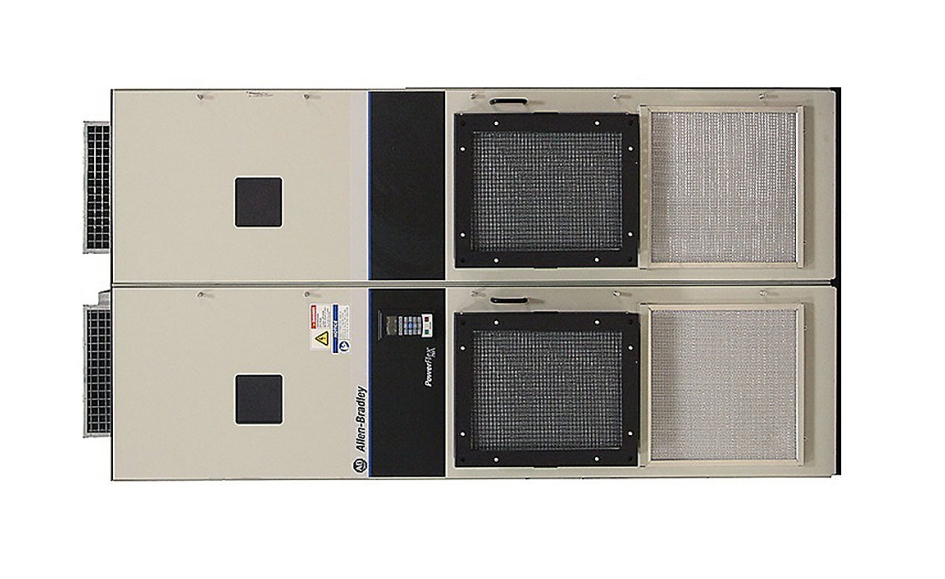
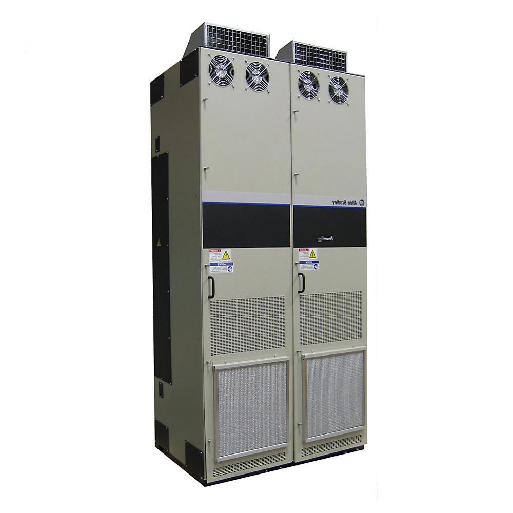
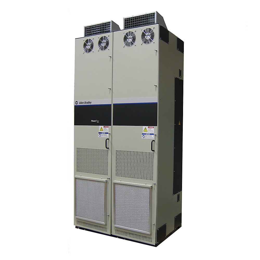
- Allen Bradley
- 20J1F3F1K8LNANNNNN
- PowerFlex AC Drive
- USA
- 2300 × 1300 × 800 mm
- 650kg
- Xiamen, China
- New & In Stock
- T/T, PayPal, Western Union
- 1 Year
- 1-3 Working Days
- DHL, UPS, TNT, FedEx and EMS.
- 24-Hour Service
- COO
- 4
Our advantage

Global Logistics
We have a 10-year logistics and express cooperation agreement, so our products can be shipped to any place in the world.

Brand new and original
Our products are imported in bulk from the place of origin. Because of the cooperative relationship, our products are all original and 100% new.

24-hour service
We provide 7*24 hours service to our customers. We will be there whenever you need us.

Price advantage
All our products are priced very favorably because we have our own warehouse and supply.
| Company Information | |||
| [email protected] | |||
| Mobile | +8615980777398 | ||
| +8615980777398 | |||
| 15980777398 |
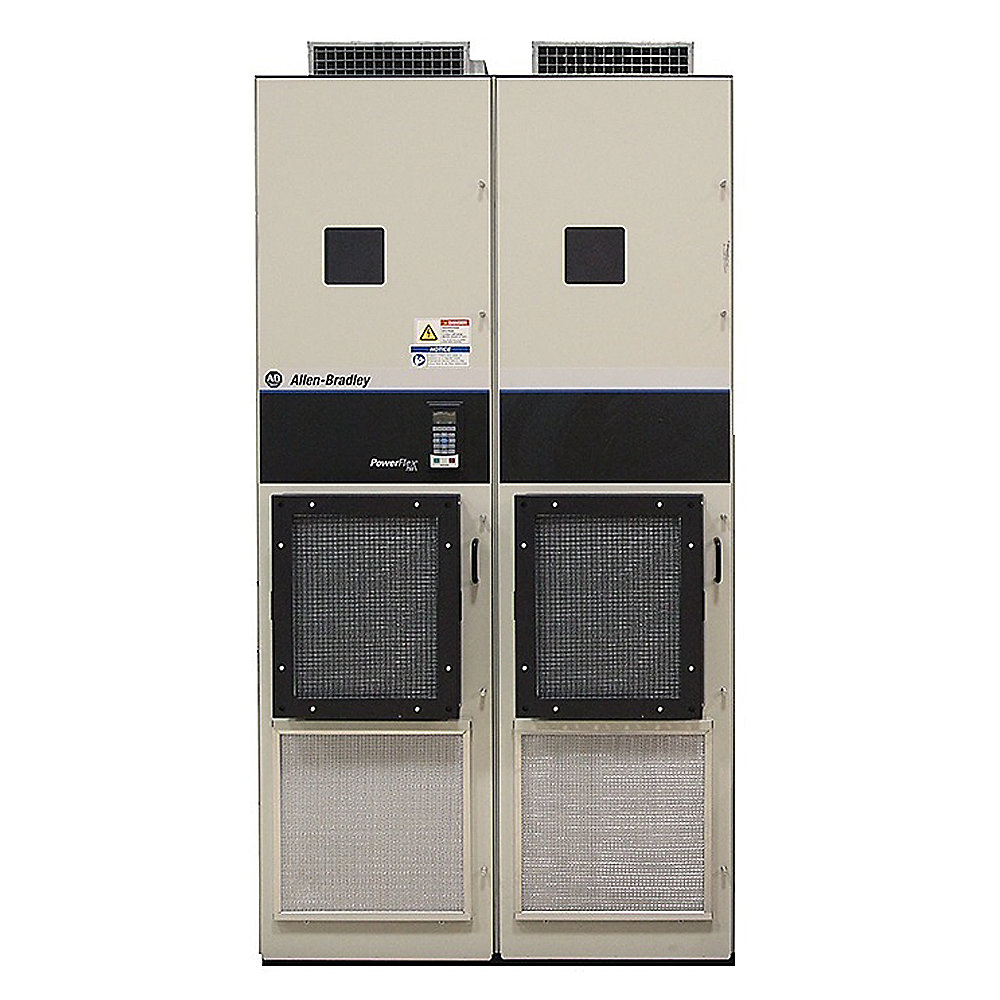
20J1F3F1K8LNANNNNN — Detailed Product Overview, Technical Specifications, Applications, Advantages and Related Models
1. Product Identification
The 20J1F3F1K8LNANNNNN is a high-power PowerFlex 755TM AFE Bus Supply configuration designed for large industrial drive systems using a common DC-bus architecture.
The model is part of the 20J1 bus-supply family and is intended for applications where several drive sections can share a centralized DC bus. The F1K8 rating identifies the approximately 1.914 MW 690 V-class configuration.
| Item | Specification |
|---|---|
| Model | 20J1F3F1K8LNANNNNN |
| Brand | Allen-Bradley |
| Product Family | PowerFlex 755T |
| Product Series | PowerFlex 755TM |
| Product Type | AFE Bus Supply |
| Configuration Family | 20J1 |
| Input Architecture | Active Front End |
| Operating Principle | Regenerative AC/DC power conversion |
| Voltage Class | 690 V AC |
| Rated Power | Approximately 1,914 kW |
| Power Class | Approximately 1.91 MW |
| Rated Current Class | Approximately 1,914 A DC-output class |
| Cooling | Air cooled |
| Installation | Floor-standing industrial system |
| Enclosure Configuration | IP21 / NEMA Type 1 class |
| Common DC Bus | Yes |
| Regenerative Capability | Yes |
| Typical Application | High-power multi-drive systems |
| Frame | Frame 11 class |
| Approx. Width | Configuration dependent, approximately 2,600–3,400 mm class |
| Approx. Depth | Approximately 720 mm class |
| Approx. Height | Approximately 2,291 mm class |
| Approx. Weight | Approximately 2,500–2,700 kg class |
| Weight Unit | kg |
The F1K8 rating corresponds to approximately 1,914 kW at 690 V AC for the AFE bus-supply configuration. The same rating is associated with Frame 11 in the relevant power-conversion configuration.
The exact mechanical dimensions and shipping weight can vary according to the complete cabinet arrangement, wiring bays and selected options. Therefore, the dimensions and weight above should be treated as engineering-level approximate values rather than guaranteed shipping measurements.
2. Product Introduction
The 20J1F3F1K8LNANNNNN is a high-power regenerative bus-supply unit designed for large industrial electrical drive systems.
Its main function is to convert incoming AC electrical power into controlled DC-bus power for connected inverter sections.
A simplified system architecture can be represented as:
Three-Phase AC Supply → AFE Bus Supply → Common DC Bus → Inverter Sections → Motors
This arrangement is different from a conventional single-motor variable-frequency drive.
A conventional VFD normally receives AC power and directly produces a variable-frequency output for one motor or one motor group.
A bus-supply architecture instead establishes a common DC-bus power source that can supply several individual inverter sections.
This makes the product particularly suitable for large machines with multiple motors, coordinated axes and significant regenerative energy.
The approximately 1.914 MW rating places this model firmly in the high-power industrial category.
It is intended for applications where electrical power requirements are measured in megawatts rather than tens or hundreds of kilowatts.
3. Product Brand and Series
| Category | Information |
|---|---|
| Brand | Allen-Bradley |
| Product Family | PowerFlex 755T |
| Product Series | PowerFlex 755TM |
| Bus-Supply Series | 20J1 |
| Product Type | AFE Bus Supply |
| Power Class | Approximately 1.91 MW |
| Voltage Class | 690 V AC |
| Main Architecture | Regenerative common DC bus |
The PowerFlex 755T platform includes regenerative, low-harmonic and common-bus solutions, with TotalFORCE-based control technology used across the product platform.
4. Catalog Number Interpretation
The catalog number is:
20J1F3F1K8LNANNNNN
The individual characters identify different aspects of the product configuration.
| Catalog Number Section | General Meaning |
|---|---|
| 20J1 | PowerFlex 755TM bus-supply family |
| F | 690 V-class rating group |
| 3 | IP21 / NEMA Type 1 class enclosure selection |
| F1K8 | Approximately 1,914 kW AFE bus-supply rating |
| L | Filtering / configuration option |
| NANNNNN | Additional configuration positions |
The exact meaning of every option character should be checked against the particular catalog-number revision when the unit is being purchased or replaced.
For a replacement project, the complete catalog number is important. Two units with the same voltage and kW rating can still have different enclosure, filtering, mechanical or factory configuration options.
5. Detailed Technical Parameters
| Parameter | Specification |
|---|---|
| Model | 20J1F3F1K8LNANNNNN |
| Brand | Allen-Bradley |
| Series | PowerFlex 755TM |
| Product Family | PowerFlex 755T |
| Product Type | AFE Bus Supply |
| Input | Three-phase AC |
| Voltage | 690 V AC class |
| Frequency | 50 Hz class / system dependent |
| Rated Power | Approx. 1,914 kW |
| Power | Approx. 1.91 MW |
| Current Class | Approx. 1,914 A |
| DC-Bus Function | Yes |
| Common DC Bus | Yes |
| Regenerative Operation | Yes |
| Active Front End | Yes |
| Harmonic-Control Architecture | Yes |
| Cooling | Air cooled |
| Enclosure | IP21 / NEMA Type 1 class |
| Installation | Floor mounted |
| Frame | Frame 11 |
| Control Platform | TotalFORCE-based PowerFlex 755T architecture |
| Application | High-power industrial drive system |
| Approx. Width | 2,600–3,400 mm class |
| Approx. Depth | 720 mm class |
| Approx. Height | 2,291 mm class |
| Approx. Weight | 2,500–2,700 kg class |
| Weight | kg |
| Construction | Large industrial cabinet / power bay |
| Main Function | Central DC-bus power conversion |
The published technical data identifies 20J…F1K8 as a Frame 11 configuration with approximately 2,146 kW light-duty output and 2,146 A continuous DC output for the corresponding common-bus inverter data; the AFE bus-supply rating itself is approximately 1,914 kW at 690 V. These ratings should not be confused with each other because bus-supply and inverter catalog tables use different rating definitions.
6. Electrical Characteristics
The main electrical characteristic of this model is its combination of 690 V-class operation and approximately 1.914 MW of power capacity.
This is a very high electrical power level.
At this scale, the product is normally incorporated into a complete electrical system containing an upstream transformer, medium- or low-voltage switchgear as appropriate to the installation, protection equipment, disconnect equipment, high-current cabling or busbars, grounding equipment and multiple inverter sections.
The bus supply establishes the DC-bus energy source for the connected drive system.
The exact DC-bus voltage and operating limits depend on the actual AC supply conditions and system configuration.
7. Common DC-Bus Architecture
The common DC bus is one of the main reasons to select a product from this family.
A typical system can be arranged as follows:
AC Supply
↓
20J1 AFE Bus Supply
↓
Common DC Bus
↓
Drive Inverter 1 → Motor 1
Drive Inverter 2 → Motor 2
Drive Inverter 3 → Motor 3
Drive Inverter 4 → Motor 4
This arrangement is particularly useful when multiple motors are part of one machine.
Instead of providing a completely separate incoming power-conversion system for every motor drive, a centralized bus supply can provide the DC power required by several inverter sections.
8. Regenerative Operation
Regenerative operation is another important feature.
A motor normally consumes electrical power when accelerating and driving a load.
During deceleration, the motor can operate as a generator.
The generated electrical energy is transferred back toward the DC bus.
In a suitable regenerative system, this energy can either be used by another connected drive section or transferred back toward the AC electrical system.
This is particularly valuable in machinery with:
- High inertia
- Frequent braking
- Rapid acceleration and deceleration
- Vertical movement
- Hoisting and lowering
- Reversing
- Large rotating equipment
- Long conveyor systems
The higher the motor power and the more frequently the machine regenerates, the more important the energy-management architecture becomes.
9. Harmonic and Power-Quality Considerations
An active-front-end system is also relevant to applications where input-current quality is important.
The power-conversion stage actively controls the relationship between the AC supply and the DC bus.
This architecture can provide substantially different input-current characteristics from a simple diode-rectifier front end.
The actual harmonic performance depends on the complete installation, including the AC system impedance, filtering configuration, transformer arrangement and operating conditions.
For this reason, harmonic compliance should be evaluated at system level rather than assumed from the drive catalog number alone.
10. Product Advantages
10.1 Very High Power Capacity
The approximately 1.914 MW rating makes this product suitable for large industrial machinery.
It is intended for power requirements well beyond the range of ordinary compact variable-frequency drives.
10.2 Centralized Power Conversion
A centralized bus supply can provide the electrical foundation for multiple inverter sections.
This can simplify the power architecture of a large machine.
Instead of designing every motor drive as an independent incoming-power system, the machine can be organized around a common DC bus.
10.3 Regenerative Energy Handling
The regenerative architecture allows the system to handle energy flowing from motors back toward the electrical supply.
This is particularly useful in high-inertia machinery.
10.4 Energy Sharing
A common DC bus can allow electrical energy to be shared among connected drive sections.
If one drive is consuming energy while another is regenerating, the regenerated energy can potentially contribute to the DC-bus power available to the other drive.
This depends on the operating state and complete system configuration.
10.5 Suitable for Multi-Motor Machinery
The product is particularly relevant when a machine contains several large motors.
Typical examples include:
- Large conveyors
- Cranes
- Hoists
- Mining equipment
- Steel-processing equipment
- Material-handling machinery
- Large process lines
- Rolling systems
- Test systems
10.6 690 V-Class Industrial System
The 690 V class is widely associated with large industrial motor systems.
At a given power level, higher voltage reduces the current required compared with a lower-voltage system.
This can influence conductor size, busbar design and electrical-distribution architecture.
11. Typical Applications
| Application | How the Product Can Be Used |
|---|---|
| Large conveyor | Central power source for multiple conveyor drives |
| Mining | High-power drive systems for material handling and processing |
| Crane | Regenerative power management during lowering and braking |
| Hoist | High-power motor systems with frequent regenerative operation |
| Steel processing | Multi-motor synchronized process equipment |
| Rolling machinery | Coordinated high-power drive sections |
| Material handling | Large multi-axis drive systems |
| Test stand | Repeated acceleration and regenerative braking |
| Large process machine | Centralized DC-bus power architecture |
| Heavy production line | Multiple synchronized motor drives |
| Large fans | High-power variable-speed systems |
| Large pumps | High-power process drive applications |
12. Application in Large Conveyor Systems
A large conveyor can have several motors distributed along the machine.
During acceleration, the motors require significant electrical power.
During normal operation, power consumption can stabilize.
During deceleration, some motors may regenerate electrical energy.
A common DC-bus architecture provides a way to coordinate these different power conditions.
The basic system can be represented as:
AC Grid → AFE → DC Bus → Drive Sections → Conveyor Motors
This architecture is particularly relevant when the conveyor is very long, heavily loaded or operated with frequent speed changes.
13. Application in Crane and Hoist Systems
Cranes and hoists have a special electrical characteristic: the direction of energy flow can change frequently.
During lifting, the motor supplies mechanical energy to the load.
During lowering, gravitational energy can cause the motor to regenerate.
During stopping, additional regenerative energy may be produced.
A regenerative common-bus system is therefore well suited to this type of operating cycle.
The final system design must still consider mechanical braking, safety functions, emergency stopping and load-control requirements separately from the electrical regeneration system.
14. Application in Mining
Mining machinery can require extremely high motor power.
Long conveyors, crushers, feeders and material-handling systems can contain multiple motors operating together.
The approximately 1.9 MW class of this model provides a suitable scale for large industrial power-conversion systems.
The common-bus arrangement can also be useful where several motors need coordinated control.
For mining environments, additional attention should be given to dust, ambient temperature, altitude, ventilation and enclosure requirements.
15. Application in Steel and Heavy Processing
Steel-processing and other heavy industrial machines frequently use multiple high-power motors.
The machine may require:
- Synchronized speed
- Coordinated torque
- Rapid acceleration
- Rapid deceleration
- Regenerative operation
- Precise tension control
- High continuous power
A common DC-bus architecture can provide an effective electrical foundation for these requirements.
16. Dimensions and Weight
Because this model belongs to the large-frame, approximately 1.9 MW class, physical installation is a major consideration.
| Mechanical Parameter | Approximate Specification |
|---|---|
| Model | 20J1F3F1K8LNANNNNN |
| Frame | Frame 11 |
| Installation | Floor standing |
| Width | Approx. 2,600–3,400 mm class |
| Depth | Approx. 720 mm class |
| Height | Approx. 2,291 mm class |
| Approx. Weight | Approx. 2,500–2,700 kg |
| Weight Unit | kg |
| Cabinet Construction | Large industrial cabinet/bay |
| Cooling | Air cooled |
| Floor Loading | Must be checked |
| Lifting Requirement | Heavy industrial lifting equipment |
| Service Clearance | Required |
| Wiring Bays | Can increase overall dimensions and weight |
The F1K8 configuration is associated with Frame 11.
Because the exact suffix includes configuration options, the final physical dimensions should be confirmed against the equipment’s mechanical drawing before fabrication of the electrical room, foundation or cabinet layout.
17. Installation Requirements
A unit of this size should be treated as a major industrial installation.
Floor Loading
With an equipment mass in the approximately 2.5-tonne class, the supporting floor or foundation should be checked before installation.
Ventilation
The equipment is air cooled and therefore requires appropriate airflow.
The electrical room must be capable of removing the heat generated during normal operation.
Electrical Clearance
Adequate working space should be maintained around the equipment.
The exact clearance depends on the installation arrangement and applicable electrical regulations.
Transportation
The equipment’s physical dimensions and weight should be considered before delivery.
Door openings, lifting points, access routes and floor loading should all be checked.
18. Five Closely Related Models in the Same Series
The following five models are useful for comparison because they are part of the same 20J1 AFE bus-supply family and cover adjacent power levels.
| Model | Product Type | Voltage | Approx. Power | Frame | Cooling | Approx. Dimensions | Approx. Weight |
|---|---|---|---|---|---|---|---|
| 20J1F3F1K1LNANNNNN | AFE Bus Supply | 690 V | 1,180 kW | 10 | Air cooled | Large cabinet | Approx. 2,100 kg class |
| 20J1F3F1K4LNANNNNN | AFE Bus Supply | 690 V | 1,456 kW | 10 | Air cooled | Large cabinet | Approx. 2,100–2,500 kg class |
| 20J1F3F1K8LNANNNNN | AFE Bus Supply | 690 V | 1,914 kW | 11 | Air cooled | Approx. 2,600–3,400 × 720 × 2,291 mm class | Approx. 2,500–2,700 kg |
| 20J1F3F2K3LNANNNNN | AFE Bus Supply | 690 V | 2,379 kW | 12 | Air cooled | Large multi-bay cabinet | Approx. 3,000 kg class |
| 20J1F3F2K7LNANNNNN | AFE Bus Supply | 690 V | 2,851 kW | 13 | Air cooled | Very large multi-bay cabinet | Approx. 4,000–5,000 kg class |
The 690 V AFE bus-supply range includes F1K1 at approximately 1,180 kW, F1K4 at approximately 1,456 kW, F1K8 at approximately 1,914 kW, F2K3 at approximately 2,379 kW and F2K7 at approximately 2,851 kW.
19. Same-Series Model Comparison
| Parameter | 20J1F3F1K1LNANNNNN | 20J1F3F1K4LNANNNNN | 20J1F3F1K8LNANNNNN | 20J1F3F2K3LNANNNNN | 20J1F3F2K7LNANNNNN |
|---|---|---|---|---|---|
| Voltage | 690 V | 690 V | 690 V | 690 V | 690 V |
| Power | ~1,180 kW | ~1,456 kW | ~1,914 kW | ~2,379 kW | ~2,851 kW |
| Frame | 10 | 10 | 11 | 12 | 13 |
| AFE | Yes | Yes | Yes | Yes | Yes |
| Common DC Bus | Yes | Yes | Yes | Yes | Yes |
| Regeneration | Yes | Yes | Yes | Yes | Yes |
| Cooling | Air cooled | Air cooled | Air cooled | Air cooled | Air cooled |
| Installation | Floor standing | Floor standing | Floor standing | Floor standing | Floor standing |
| Approx. Weight | ~2,100 kg | ~2,100–2,500 kg | ~2,500–2,700 kg | ~3,000 kg | ~4,000–5,000 kg |
| Application | High-power | High-power | Very high-power | Multi-megawatt | Multi-megawatt |
The F1K8 configuration is one step above F1K4 and below F2K3 in the 690 V AFE bus-supply rating sequence.
20. Five Related Models from the Broader Product Range
The following models are from related industrial drive families and can be considered when the application does not require a 1.9 MW common-bus supply.
They are not direct replacements for the 20J1F3F1K8LNANNNNN.
| Model | Product Family | Product Type | Voltage Class | Approx. Power Class | Cooling | Approx. Dimensions | Approx. Weight |
|---|---|---|---|---|---|---|---|
| 20F1AGF012JN0NNNNN | PowerFlex 753 | AC Drive | 690 V class | Approx. 7.5 kW | Air cooled | Approx. 665 × 308 × 346 mm | Approx. 38.6 kg |
| 20F1AGF020JN0NNNNN | PowerFlex 753 | AC Drive | 690 V class | Approx. 15 kW | Air cooled | Approx. 665 × 308 × 346 mm | Approx. 38.6 kg |
| 20G2ANF050JA0NNNNN | PowerFlex 755TS | AC Drive | 690 V class | Approx. 45–50 kW | Air cooled | Configuration dependent | Configuration dependent |
| 20G2ANF119JA0NNNNN | PowerFlex 755TS | AC Drive | 690 V class | Approx. 110–120 kW | Air cooled | Configuration dependent | Configuration dependent |
| 20G2ANF212JA0NNNNN | PowerFlex 755TS | AC Drive | 690 V class | Approx. 200–220 kW | Air cooled | Configuration dependent | Configuration dependent |
These products are considerably smaller and serve individual motor-control applications rather than the large centralized bus-supply role of the 20J1F3F1K8LNANNNNN.
21. Main Model vs. Related Drive Models
| Feature | 20J1F3F1K8LNANNNNN | PowerFlex 753 Class | PowerFlex 755TS Class |
|---|---|---|---|
| Main Function | AFE bus supply | Individual AC motor drive | Advanced AC motor drive |
| Power Level | ~1.914 MW | Low/medium power | Medium/high power |
| Common DC Bus | Yes | Application dependent | Application dependent |
| Regenerative Function | Core architecture | Configuration dependent | Configuration dependent |
| Installation | Large floor-standing cabinet | Cabinet/panel | Cabinet/panel |
| Typical Number of Motors | Multiple inverter sections | Usually one | Usually one |
| Approx. Weight | ~2,500–2,700 kg | Tens of kg at smaller ratings | Frame dependent |
| Main Application | Large multi-drive system | Individual motor | High-performance motor/process control |
| System Architecture | Centralized | Distributed | Distributed/system based |
22. Major Product Advantages in Detail
High-Power Industrial Capability
The approximately 1.914 MW rating makes this configuration appropriate for large machines with very high installed motor power.
The product is intended for applications where the electrical power requirement is too large for conventional compact drives.
Regenerative Power Management
Regeneration is particularly important for applications where mechanical energy repeatedly returns to the electrical system.
Examples include cranes, hoists, conveyors and large rotating machinery.
A regenerative AFE architecture provides a controlled electrical path for this returned energy.
Common-Bus Energy Sharing
A common DC bus provides the possibility of sharing energy among different drive sections.
This can be valuable in machines where different axes have different load cycles.
Centralized Architecture
The bus supply creates a central power-conversion point.
This can make large machine electrical architecture easier to organize.
High-Voltage Operation
The 690 V-class configuration is appropriate for large industrial systems.
The higher voltage allows the required power to be handled at a lower current than an equivalent lower-voltage system.
23. Typical Industries
| Industry | Possible Application |
|---|---|
| Mining | Conveyors, crushers, material handling |
| Metals | Rolling equipment and processing |
| Steel | High-power synchronized drive systems |
| Cement | Conveyors, fans and process machinery |
| Marine | Large propulsion and auxiliary systems where applicable |
| Material Handling | Cranes, hoists and conveyors |
| Manufacturing | Large production machinery |
| Paper | Large process and tension-control systems |
| Power Generation | Large auxiliary machinery |
| Heavy Processing | Multi-motor production systems |
24. Recommended Selection Criteria
When choosing a related model, the following parameters should be checked rather than comparing only the kW rating.
| Selection Parameter | Why It Matters |
|---|---|
| AC voltage | Must match the electrical supply |
| Power rating | Must support continuous machine demand |
| Current rating | Must support motor and transient requirements |
| Regeneration | Important for loads returning energy |
| DC-bus voltage | Must match connected inverter sections |
| Frame size | Determines mechanical installation |
| Cooling | Determines thermal and ventilation requirements |
| Enclosure | Determines environmental protection |
| Filtering | Influences input power quality |
| Cabinet width | Must fit available space |
| Cabinet depth | Important for electrical-room layout |
| Cabinet height | Important for transportation and installation |
| Weight | Important for floor loading and handling |
| Communication | Must match the control system |
| Options | Must match the existing installation |
25. Replacement Considerations
If the purpose is to replace an existing 20J1F3F1K8LNANNNNN, selecting another 1.9 MW drive simply because it has the same nominal power is not sufficient.
The following characteristics should be checked:
Voltage
The replacement should be compatible with the existing 690 V-class electrical system.
Power
The replacement needs to provide adequate continuous and transient power.
Current
The current rating must be suitable for the connected DC-bus load.
Frame
A different frame can change the cabinet dimensions and installation requirements.
Cooling
A different cooling configuration can change the electrical-room ventilation requirements.
Enclosure
The enclosure configuration must be suitable for the installation environment.
Filtering
The input filtering configuration should be checked.
DC Bus
The replacement must be compatible with the connected inverter sections.
Regeneration
If the machine relies on regenerative operation, the replacement architecture must support the required energy flow.
Control
The replacement must be compatible with the machine-control system.
26. Mechanical Considerations
The approximate 2,500–2,700 kg equipment weight is one of the most important mechanical considerations.
The installation area should be checked for adequate floor loading.
The delivery route should also be checked.
Particular attention should be paid to:
- Door openings
- Ceiling height
- Turning space
- Floor strength
- Lifting capacity
- Forklift capacity
- Crane access
- Cabinet positioning
- Maintenance access
The actual final weight may differ from the approximate value because of cabinet sections, wiring bays and other factory options.
27. Thermal Considerations
A 1.9 MW-class power-conversion system can generate substantial heat.
Although the air-cooled design provides a practical cooling method, the installation still needs adequate ventilation.
The engineering calculation should consider:
- Equipment losses
- Ambient temperature
- Room volume
- Airflow
- Altitude
- Adjacent equipment
- Cabinet arrangement
- Filter condition
- Maintenance requirements
The ventilation system should be designed for the complete electrical room rather than considering the bus supply in isolation.
28. Product Selection Summary
| Category | Main Specification |
|---|---|
| Model | 20J1F3F1K8LNANNNNN |
| Brand | Allen-Bradley |
| Product Family | PowerFlex 755T |
| Product Series | PowerFlex 755TM |
| Bus Supply Series | 20J1 |
| Product Type | AFE Bus Supply |
| Voltage | 690 V AC class |
| Power | Approx. 1,914 kW |
| Power Level | Approx. 1.91 MW |
| Current Class | Approx. 1,914 A |
| Frame | 11 |
| Cooling | Air cooled |
| Enclosure | IP21 / NEMA Type 1 class |
| DC Bus | Yes |
| Regeneration | Yes |
| Installation | Floor standing |
| Approx. Width | 2,600–3,400 mm class |
| Approx. Depth | 720 mm class |
| Approx. Height | 2,291 mm class |
| Approx. Weight | 2,500–2,700 kg class |
| Weight Unit | kg |
| Primary Application | High-power multi-drive systems |
| Secondary Applications | Mining, conveyors, cranes, hoists, metals, heavy processing |
| Main Feature | High-power regenerative common DC-bus architecture |
29. Overall Product Description
The 20J1F3F1K8LNANNNNN is a high-power PowerFlex 755TM AFE Bus Supply designed for large industrial drive systems.
Its approximately 1,914 kW rating places it in the megawatt-class category.
The 690 V electrical configuration makes it suitable for large industrial power-distribution systems, while the AFE architecture provides a controlled interface between the AC electrical supply and the common DC bus.
The most important application characteristic is its ability to form the central power-conversion section of a multi-drive system.
Several inverter sections can be connected to the common DC bus, allowing the machine to operate as a coordinated electrical system rather than a collection of completely independent drives.
This is particularly useful for machinery containing several high-power motors.
Conveyors, cranes, hoists, mining equipment, steel-processing machinery, rolling equipment and large process systems are typical examples of applications where this architecture can be considered.
The regenerative capability is another important feature.
When a motor decelerates or a mechanical load drives the motor, electrical energy can flow back toward the DC bus. In a suitable regenerative system, this energy can be shared with other drive sections or transferred back toward the AC system.
From a physical standpoint, this is a very large industrial power-conversion system.
The approximately 2,600–3,400 mm width, approximately 720 mm depth and approximately 2,291 mm height should be used as an initial planning range, while the approximately 2,500–2,700 kg weight class should be considered when planning transportation, lifting and floor loading.
The F1K8 rating is the key distinction from the nearby F1K1 and F1K4 configurations. The F1K8 version provides approximately 1.914 MW, while the adjacent configurations provide approximately 1.180 MW and 1.456 MW respectively. The next larger F2K3 configuration moves into the approximately 2.379 MW class.
For procurement, replacement or system design, the complete catalog number 20J1F3F1K8LNANNNNN should be treated as the reference identifier. Voltage, power, frame, enclosure, filtering, cabinet arrangement and option positions should all be checked before selecting an alternative.
In practical terms, this model is best understood as a large regenerative power-conversion and common-DC-bus supply for multi-motor industrial machinery, rather than as an ordinary single-motor frequency inverter.