

ProductPRODUCT
Featured products
Contact Us
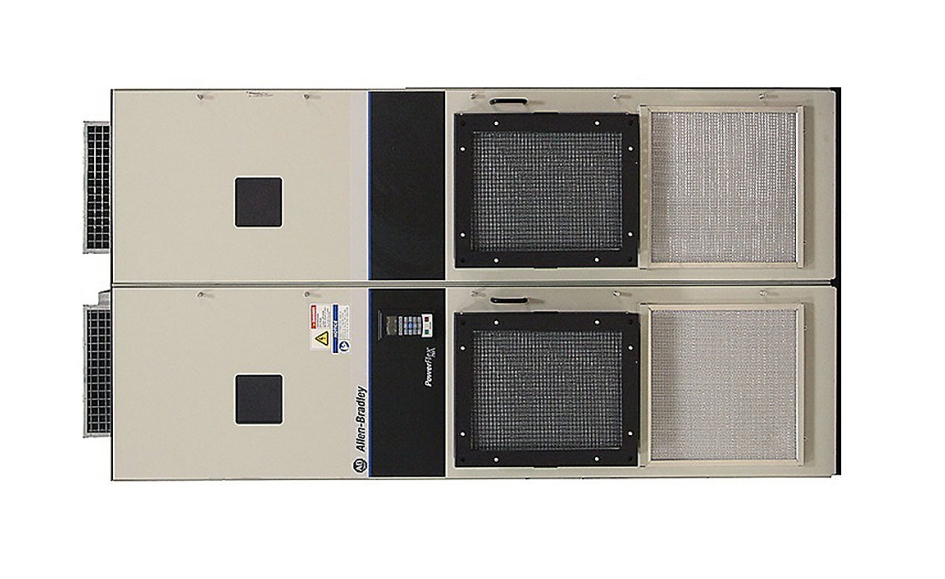
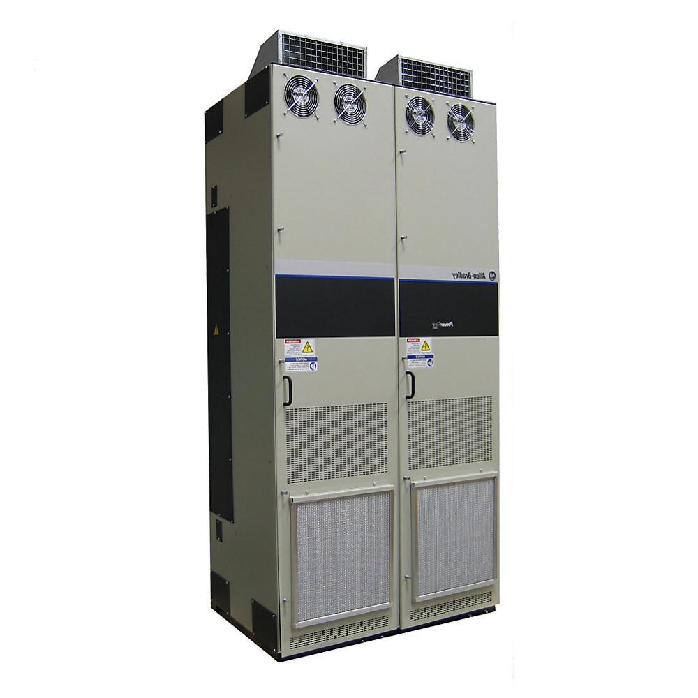
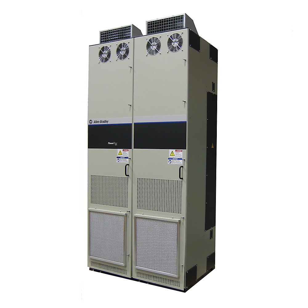
- Allen Bradley
- 20J1F3D505LNDNNNNN
- PowerFlex AC Drive
- USA
- 1,000–1,600 H × 550–900 W × 500–900 D mm
- 260kg
- Xiamen, China
- New & In Stock
- T/T, PayPal, Western Union
- 1 Year
- 1-3 Working Days
- DHL, UPS, TNT, FedEx and EMS.
- 24-Hour Service
- COO
- 5
Our advantage

Global Logistics
We have a 10-year logistics and express cooperation agreement, so our products can be shipped to any place in the world.

Brand new and original
Our products are imported in bulk from the place of origin. Because of the cooperative relationship, our products are all original and 100% new.

24-hour service
We provide 7*24 hours service to our customers. We will be there whenever you need us.

Price advantage
All our products are priced very favorably because we have our own warehouse and supply.
| Company Information | |||
| [email protected] | |||
| Mobile | +8615980777398 | ||
| +8615980777398 | |||
| 15980777398 |
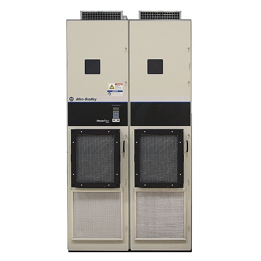
Allen-Bradley 20J1F3D505LNDNNNNN PowerFlex 750 Bus Supply
1. Product Overview
The Allen-Bradley 20J1F3D505LNDNNNNN is an air-cooled PowerFlex 750 Bus Supply designed for high-power industrial drive systems using a common DC-bus architecture. The unit is identified as an AFE regenerative bus supply, with a rated input of 480 VAC and a listed current rating of 519 A.
The D505 configuration belongs to the high-power end of the PowerFlex 750 Bus Supply family and is intended for installations where several drive sections or motor loads share a common DC bus. Instead of treating every motor drive as a completely independent power-conversion system, the common-bus arrangement allows electrical energy to be distributed through a shared DC link.
This architecture is particularly useful in large production machines, process lines, material-handling systems, coordinated motion equipment, and other applications where multiple drive axes operate as part of one integrated electrical system.
The 20J1F3D505LNDNNNNN is also configured as an AFE regenerative unit. Active Front End technology allows the converter to control the relationship between the AC supply and the DC bus while providing a path for regenerative energy to be returned toward the incoming electrical network rather than being dissipated only through braking resistors.
The catalog information identifies the unit as a PowerFlex 750 Bus Supply and lists the product as discontinued, with the discontinuation date stated as December 20, 2021.
For existing installations, this makes the model especially relevant when maintaining legacy PowerFlex systems, replacing an installed bus supply, restoring production equipment, or evaluating migration paths to a newer bus-supply architecture.
2. Basic Product Parameters
| Parameter | Specification |
|---|---|
| Model | 20J1F3D505LNDNNNNN |
| Brand | Allen-Bradley |
| Product Family | PowerFlex 750 Bus Supplies |
| Product Type | Air-Cooled 750 Bus Supply |
| Configuration | D505 |
| Power Conversion Type | AFE Regenerative |
| Input Voltage | 480 VAC |
| Input Current | 519 A |
| Phase | 3-phase industrial power configuration |
| Application Architecture | Common DC Bus |
| Cooling Method | Air cooled |
| Mounting Style | Floor-mounted industrial installation |
| Protection Class | Type 1 / IP21 configuration associated with this D505 family configuration |
| Frame | Large-frame/high-power PowerFlex 750 bus-supply construction |
| Regeneration | Yes |
| EMC Configuration | Dependent on exact catalog suffix and installed options |
| Typical Application | Common DC-bus drive systems |
| Product Status | Discontinued |
| Approx. Dimensions | Approx. 1,000–1,600 mm H × 550–900 mm W × 500–900 mm D |
| Approx. Weight | Approx. 140–260 kg |
| Installation Environment | Industrial control cabinet / electrical room / drive system area |
| Control Architecture | PowerFlex common-bus system |
| Primary Function | AC-to-DC bus power conversion and regenerative energy management |
The 519 A at 480 VAC rating is the important electrical identifier for this exact catalog number. The manufacturer product record identifies the input type as AFE REGENERATIVE and lists 519 A and 480 V AC.
The dimensional and weight figures above should be treated as engineering-planning estimates rather than certified shipping dimensions. For cabinet fabrication, lifting calculations, transportation planning, or replacement work, the exact mechanical drawing and nameplate of the individual unit should be used.
3. Product Model Interpretation
The catalog number 20J1F3D505LNDNNNNN contains a number of configuration elements that identify the product family and construction.
The 20J1 portion identifies the PowerFlex 750 Bus Supply product generation.
The F3 portion is associated with the large industrial floor-mounted configuration used within this product family.
The D505 portion identifies the particular high-power configuration.
The LND portion forms part of the electrical and option configuration, including the specific power and interface arrangement.
The remaining NNNNN characters represent additional configuration positions within the catalog-number structure.
Because PowerFlex catalog numbers can contain option-dependent suffixes, two models that look very similar should not automatically be considered electrically interchangeable. The complete catalog number, nameplate information, voltage class, current rating, options, and application requirements should be checked before replacement.
4. Product Introduction
The 20J1F3D505LNDNNNNN is intended for industrial applications requiring a large centralized DC power source for multiple drive units.
In a conventional multi-drive installation, each AC drive can have its own rectifier and DC-link system. A common DC-bus architecture changes this arrangement by allowing several drive sections to obtain DC power from a shared bus supply.
This approach can reduce duplicated front-end conversion equipment and can improve the way regenerative energy is handled between multiple drive axes.
For example, when one motor is accelerating while another motor is decelerating, energy generated by the decelerating motor can potentially be transferred through the common DC bus and used by another drive. This can reduce the amount of energy that needs to be dissipated as heat.
The AFE regenerative design provides an additional benefit in applications where substantial regenerative operation occurs. Rather than relying exclusively on braking resistors, the power-conversion system can manage energy flowing back toward the AC supply.
The result is a drive architecture suited to large coordinated machines where energy flow between multiple axes is an important part of the overall electrical design.
5. Main Functional Characteristics
Active Front End Regenerative Operation
The most important functional characteristic of this model is its AFE regenerative architecture.
An Active Front End can provide controlled power exchange between the AC supply and the DC bus. In regenerative operation, energy produced by the motor-side drives can be transferred back through the bus supply toward the incoming electrical system.
This is particularly useful for machinery with frequent braking, lowering, deceleration, or overhauling-load conditions.
Common DC-Bus Architecture
The product is designed around a common DC-bus concept.
Multiple compatible PowerFlex drive sections can be connected to a shared DC-link arrangement, allowing the bus supply to serve a group of coordinated loads.
This architecture is frequently considered for large machines containing several motors because it provides a centralized approach to DC-bus power conversion.
High-Current Industrial Power Conversion
With a listed input current of 519 A at 480 VAC, the D505 configuration is intended for substantial industrial power systems rather than small standalone machinery.
The high-current architecture requires appropriate upstream protection, conductor sizing, busbar design, grounding, cabinet ventilation, short-circuit coordination, and thermal management.
Installation design should therefore be performed as part of the complete drive-system engineering process rather than treating the bus supply as an isolated component.
Air-Cooled Construction
The 20J1F3D505LNDNNNNN uses an air-cooled design.
Air cooling is a practical arrangement for large industrial drive installations where forced ventilation can be incorporated into the electrical-room or enclosure design.
Proper airflow is essential. Filters, fans, ventilation openings, cabinet temperature, ambient temperature, and heat dissipation should all be considered during installation.
6. Typical Applications
Material Handling
The unit can be used in large material-handling systems where several motors operate together.
Examples include conveyors, transfer systems, lifting machinery, storage systems, and large automated material movement equipment.
A common DC bus can be useful when different motor axes repeatedly accelerate and decelerate because energy can be shared through the DC-link system.
Cranes and Hoisting Systems
Regenerative operation is particularly relevant to cranes and hoisting equipment.
When a load is lowered, the motor can operate in a regenerative condition. An AFE-based bus supply provides a controlled electrical path for handling this energy.
The overall system must still be engineered for the specific crane duty cycle, load characteristics, braking requirements, safety architecture, and applicable standards.
Large Conveyor Systems
Long conveyors may contain multiple motor-driven sections.
A centralized bus-supply architecture can provide a common electrical foundation for multiple drive sections, making it suitable for large conveyor installations where coordinated acceleration, deceleration, and speed control are required.
Mining Equipment
Large mining machinery frequently contains multiple high-power motors.
Applications can include material conveyors, crushers, mills, stackers, reclaimers, and other large electrically driven equipment.
The high-current architecture of the D505 configuration makes it suitable for consideration in large industrial power-conversion systems where environmental conditions and duty cycles are properly addressed.
Metal Processing
Steel and metal-processing machinery often requires coordinated control of multiple motors.
Rolling, feeding, positioning, tensioning, and material-transfer systems can benefit from common-bus architectures when the electrical design requires coordinated energy management between drive sections.
Machine Tools and Large Machine Systems
Large machine tools may have several motor axes, auxiliary motors, spindle systems, and other electrical loads.
A common DC bus can provide a centralized power architecture for suitable multi-axis applications.
Process Machinery
Process plants may use multiple large motors operating under changing load conditions.
The regenerative capabilities of an AFE system can be useful in processes where energy repeatedly moves between motoring and generating operation.
7. Advantages
1. Regenerative Energy Handling
One of the main advantages of the 20J1F3D505LNDNNNNN is its regenerative capability.
Applications with frequent deceleration or overhauling loads can potentially return regenerated energy to the AC system instead of dissipating all of it through braking resistors.
This can reduce thermal losses associated with conventional resistor-based braking systems.
2. Common DC-Bus Energy Sharing
A common DC bus allows energy to move between compatible drive sections.
If one motor is braking while another motor is accelerating, the system can potentially reuse part of the available regenerative energy.
This makes the common-bus concept attractive for coordinated multi-axis machinery.
3. High-Power Capability
The 519 A / 480 VAC configuration places this model in a high-current industrial application range.
It is intended for large electrical systems rather than compact machine applications.
4. Centralized Power Architecture
Instead of providing completely independent front ends for every drive section, a common-bus system can centralize the main AC-to-DC power conversion function.
This can simplify the overall architecture of large multi-drive systems when the system is engineered appropriately.
5. Suitable for Coordinated Multi-Motor Systems
The PowerFlex 750 Bus Supply architecture is particularly relevant to machines in which several motors need to operate as a coordinated system.
The common DC bus creates a shared electrical platform for compatible drive sections.
6. Air-Cooled Industrial Construction
The air-cooled design is appropriate for industrial electrical rooms and large control enclosures where forced ventilation and thermal management can be engineered into the installation.
7. Good Fit for Legacy PowerFlex Installations
Because the model is a PowerFlex 750 Bus Supply, it can be particularly relevant to maintenance and retrofit work involving existing PowerFlex common-bus systems.
For an existing machine, maintaining the original architecture can sometimes simplify engineering compared with completely redesigning the electrical system.
8. Important Installation Considerations
The 20J1F3D505LNDNNNNN is a high-power electrical device, so installation should be treated as part of a complete engineered system.
Incoming AC protection must be properly coordinated with the rated current and system short-circuit requirements.
Cable and busbar selection should consider continuous current, temperature, installation method, voltage drop, short-circuit withstand, and applicable electrical codes.
The common DC bus also requires careful attention to DC voltage levels, conductor insulation, busbar spacing, disconnecting means, precharge arrangements, and protective devices.
Regenerative operation introduces additional system-level considerations because power can flow in both directions between the AC network and the drive system.
The installation should also provide suitable ventilation and heat removal. Air-cooled equipment can require substantial airflow, particularly when operating continuously at high load.
9. Dimensions and Weight
The exact mechanical dimensions and shipping weight should be confirmed from the applicable mechanical drawing for the specific unit and configuration.
For preliminary cabinet planning, a reasonable engineering estimate is:
| Mechanical Parameter | Planning Value |
|---|---|
| Height | Approx. 1,000–1,600 mm |
| Width | Approx. 550–900 mm |
| Depth | Approx. 500–900 mm |
| Approx. Weight | 140–260 kg |
| Mounting | Floor-mounted |
| Cooling | Forced-air / air-cooled |
| Installation Space | Allow additional clearance for airflow, wiring, maintenance and lifting |
These values are intended for preliminary layout work only.
For final cabinet design, transportation calculations, foundation design, lifting equipment selection, and replacement work, the exact dimensions and weight of the installed unit should be verified against its nameplate and mechanical documentation.
10. Recommended Same-Series or Related Models
The following models are useful for comparison within the PowerFlex 750 Bus Supply family or closely related D-series configurations. The exact electrical ratings and option combinations should be checked against the complete catalog number before selecting a substitute.
| Model | Product Type | Configuration | Typical Relationship | Key Parameter |
|---|---|---|---|---|
| 20J1F3D302JNDNNNNN | PowerFlex 750 Bus Supply | D302 | Lower-power related D-series configuration | Common DC bus |
| 20J1F3D3K4LNDNNNNN | PowerFlex 750 Bus Supply | D3K4 | Higher-power D-series configuration | Air-cooled bus supply |
| 20J1F3D430LNDNNNNN | PowerFlex 750 Bus Supply | D430 | Related D-series configuration | AFE/common-bus architecture |
| 20J1F3D545LNDNNNNN | PowerFlex 750 Bus Supply | D545 | Closely related high-power configuration | Common DC bus |
| 20J1F3D710LNDNNNNN | PowerFlex 750 Bus Supply | D710 | Higher-capacity related configuration | High-power bus supply |
These models belong to the same general PowerFlex 750 Bus Supply catalog family, and D505 appears alongside other D-series air-cooled bus-supply configurations in catalog listings.
The model numbers should not be interpreted as direct drop-in replacements solely from the D-number. Voltage class, current rating, mounting arrangement, options, protection, control configuration, and the requirements of the existing DC-bus system must all be checked.
11. Five Same-Brand Comparison Models
The following five models are useful Allen-Bradley comparison products when evaluating high-power PowerFlex drive and bus-supply architectures.
| Model | Product Family | Voltage Class | Power / Current Information | Typical Use |
|---|---|---|---|---|
| 20J1F3D505JNDNNNNN | PowerFlex 750 Bus Supply | 480 VAC class | D505 configuration | Related AFE bus-supply application |
| 20J1F3D505LNDNNNNN-C1-P17 | PowerFlex 750 Bus Supply | 480 VAC | 485 A configuration listed for the C1-P17 version | High-power regenerative bus system |
| 20GEF3D505LNDNNNNN-C0 | PowerFlex 755TR XT AC Drive | 480 VAC | LD 450 HP / 545 A; ND 400 HP / 505 A; HD 350 HP / 430 A | Regenerative and low-harmonic drive system |
| 20GEF3F505LNDNNNNN | PowerFlex 755TR XT AC Drive | 690 VAC | LD 560 kW / 565 A; ND 500 kW / 505 A; HD 400 kW / 415 A | High-voltage regenerative drive system |
| 20J1F3D960LNDNNNNN | PowerFlex 750 Bus Supply | High-power configuration | D960 configuration | Very high-power common-bus architecture |
The C1-P17 version is specifically described as an air-cooled AFE regenerative 750 Bus Supply, with a 480 VAC, three-phase configuration and 485 A rating in the listed configuration.
The 20GEF3D505LNDNNNNN-C0 is a related regenerative PowerFlex 755TR XT configuration and is listed at 480 VAC with LD 450 HP / 545 A, ND 400 HP / 505 A, and HD 350 HP / 430 A.
The 20GEF3F505LNDNNNNN uses a 690 VAC configuration and is listed at LD 560 kW / 565 A, ND 500 kW / 505 A, and HD 400 kW / 415 A, making it a useful comparison when a higher-voltage architecture is being considered.
12. Product Family
The 20J1F3D505LNDNNNNN belongs to the PowerFlex 750 Bus Supplies family.
This family is designed around large industrial drive-system architectures where a bus supply provides DC power for compatible PowerFlex drive sections.
The family includes multiple current and power configurations, allowing engineers to select a bus supply according to the required machine load, DC-bus capacity, regenerative duty, and system voltage.
The D505 configuration represents one of the larger configurations in this family.
13. Brand
Brand: Allen-Bradley
Allen-Bradley is widely associated with industrial automation equipment, motor control, drives, PLC systems, operator interfaces, safety products, and industrial control components.
Within the drive portfolio, the PowerFlex family covers a broad range of variable-frequency drive and power-conversion products.
The 20J1F3D505LNDNNNNN specifically belongs to the PowerFlex 750 Bus Supply product group.
14. Product Status and Replacement Consideration
The 20J1F3D505LNDNNNNN is listed as discontinued, with the discontinuation date identified as December 20, 2021. A replacement product is indicated in the current product record.
For an existing machine, the discontinued status does not automatically mean that the installed unit should be replaced immediately.
The more important questions are whether the existing unit remains serviceable, whether spare units are available, whether repair support is practical, and whether the machine’s control architecture requires the original catalog configuration.
When replacing an installed unit, the complete catalog number should be matched rather than comparing only the D505 designation.
15. Maintenance Considerations
Because this is a large air-cooled power-conversion device, maintenance should focus heavily on cooling and electrical connections.
Cooling fans, airflow paths, filters, heat sinks, and cabinet ventilation should be inspected according to the maintenance schedule used for the installation.
Accumulated dust can restrict airflow and increase operating temperature.
Electrical terminals and bus connections should be inspected for signs of overheating, discoloration, looseness, or abnormal mechanical stress.
The DC bus should always be treated as a potentially hazardous energy source. Appropriate lockout, verification of zero-energy state, discharge waiting periods, and qualified electrical maintenance procedures are essential before service work.
16. Engineering Selection Checklist
Before selecting the 20J1F3D505LNDNNNNN for an application, engineers should verify:
| Selection Item | Requirement |
|---|---|
| AC Input Voltage | Verify 480 VAC system compatibility |
| Input Current | Verify system demand against 519 A rating |
| Motor Load | Calculate complete connected motor load |
| Regenerative Duty | Determine frequency and duration of regeneration |
| DC-Bus Voltage | Verify compatibility with connected drive sections |
| Drive Compatibility | Confirm all connected PowerFlex units support the intended common-bus arrangement |
| Short-Circuit Rating | Verify system SCCR and protection requirements |
| Incoming Protection | Size according to applicable electrical standards |
| Cable / Busbar | Verify continuous and fault-duty requirements |
| Cooling | Provide adequate forced-air ventilation |
| Ambient Temperature | Verify against the installation environment |
| Cabinet Clearance | Allow sufficient maintenance and airflow space |
| Grounding | Verify protective-earth and system grounding requirements |
| Harmonic Requirements | Evaluate the AFE configuration and site power-quality requirements |
| Regeneration | Confirm the utility system can accept regenerated power |
| Mechanical Installation | Verify exact dimensions and mounting details |
| Weight | Confirm actual unit weight before lifting |
| Lifecycle | Consider discontinued-product maintenance strategy |
17. Practical Application Summary
The 20J1F3D505LNDNNNNN is best understood as a large air-cooled, AFE regenerative PowerFlex 750 Bus Supply for common-DC-bus drive systems.
Its 480 VAC and 519 A specification places it in a substantial industrial power range.
The common-bus architecture makes it suitable for machines containing multiple coordinated motor drives, while the regenerative front end provides a controlled method of handling electrical energy produced during regenerative operation.
Typical applications include heavy material handling, cranes, hoists, conveyors, mining machinery, metal processing, large production lines, and other multi-drive systems.
The main engineering benefits are centralized DC-bus power conversion, regenerative energy handling, energy sharing between compatible drive axes, and integration into large PowerFlex drive architectures.
For an existing installation, the exact suffix is particularly important because option codes can affect enclosure configuration, interface equipment, protection, EMC characteristics, and installation requirements.
18. Final Technical Summary
| Item | Details |
|---|---|
| Model | 20J1F3D505LNDNNNNN |
| Brand | Allen-Bradley |
| Series | PowerFlex 750 Bus Supplies |
| Product Type | Air-Cooled Bus Supply |
| Architecture | Common DC Bus |
| Front End | AFE Regenerative |
| AC Input | 480 VAC |
| Rated Current | 519 A |
| Phase | 3 Phase |
| Cooling | Air Cooled |
| Mounting | Floor Mount |
| Approx. Dimensions | 1,000–1,600 H × 550–900 W × 500–900 D mm |
| Approx. Weight | 140–260 kg |
| Main Function | DC-bus power conversion |
| Regeneration | Supported |
| Typical System | Multi-drive common-bus system |
| Typical Applications | Conveyors, cranes, mining, material handling, process machinery, metal processing |
| Lifecycle | Discontinued |
| Replacement Planning | Verify exact electrical, mechanical, and option compatibility before replacement |
The 20J1F3D505LNDNNNNN is therefore a high-power industrial bus-supply component intended for demanding common-DC-bus applications. Its combination of 480 VAC input, 519 A current capability, air-cooled construction, and AFE regenerative operation makes it particularly relevant to large multi-drive systems where regenerative energy management and coordinated motor operation are important.
For procurement, retrofit, or maintenance work, the complete catalog number should always be matched with the existing nameplate and system configuration. The approximate dimensions and weight provided here are suitable for preliminary planning, while the final mechanical drawing should be used for cabinet, lifting, transportation, and installation calculations.