

ProductPRODUCT
Featured products
Contact Us
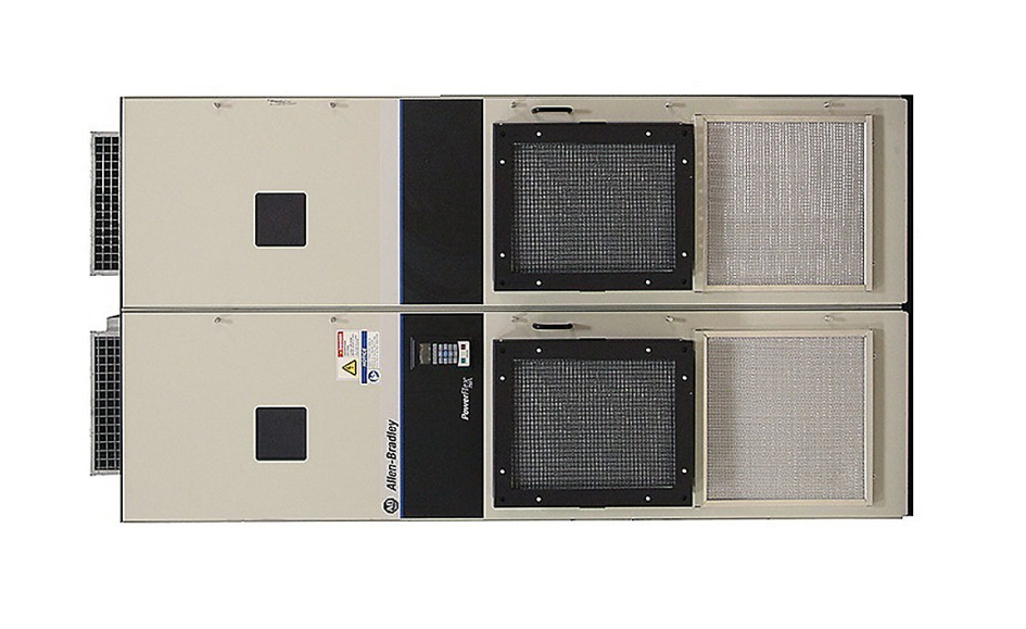
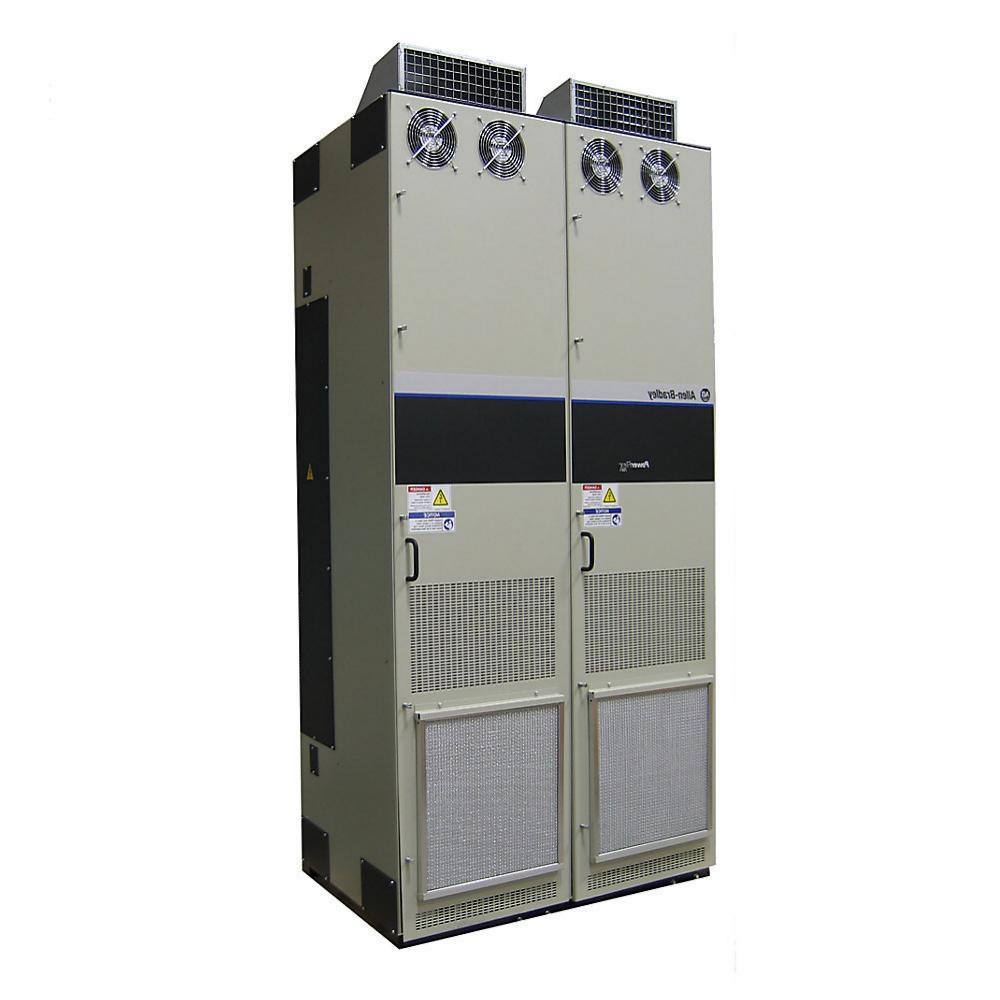
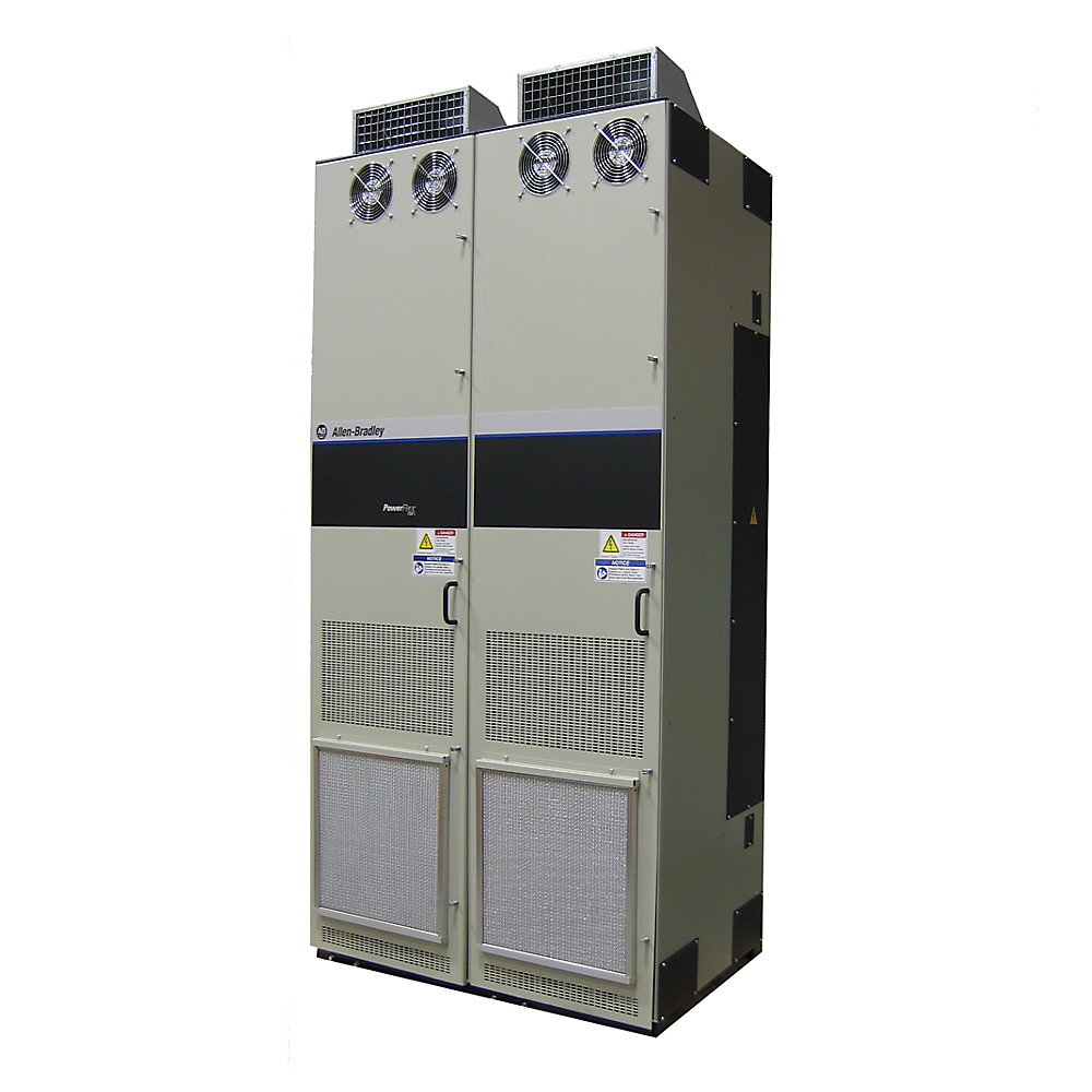
- Allen Bradley
- 20J1F3C302LNANNNNN
- PowerFlex AC Drive
- USA
- 1,000–1,300 × 500–700 × 400–600 mm
- 160kg
- Xiamen, China
- New & In Stock
- T/T, PayPal, Western Union
- 1 Year
- 1-3 Working Days
- DHL, UPS, TNT, FedEx and EMS.
- 24-Hour Service
- COO
- 4
Our advantage

Global Logistics
We have a 10-year logistics and express cooperation agreement, so our products can be shipped to any place in the world.

Brand new and original
Our products are imported in bulk from the place of origin. Because of the cooperative relationship, our products are all original and 100% new.

24-hour service
We provide 7*24 hours service to our customers. We will be there whenever you need us.

Price advantage
All our products are priced very favorably because we have our own warehouse and supply.
| Company Information | |||
| [email protected] | |||
| Mobile | +8615980777398 | ||
| +8615980777398 | |||
| 15980777398 |
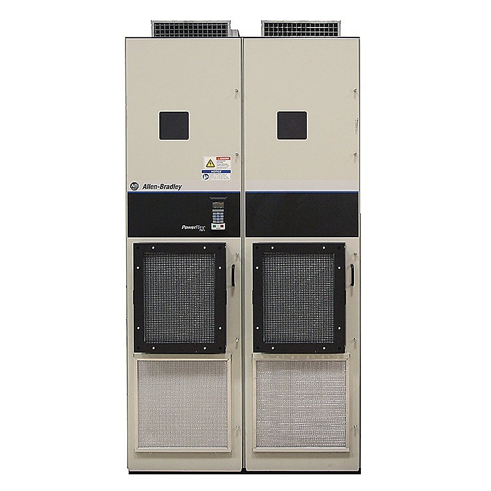
Allen-Bradley 20J1F3C302LNANNNNN PowerFlex 750 Bus Supply
1. Product Identification
The Allen-Bradley 20J1F3C302LNANNNNN is a high-power PowerFlex 750 Bus Supply designed for industrial drive systems requiring a centralized DC-bus power architecture.
The product belongs to the air-cooled PowerFlex 750 bus-supply family and is associated with the PowerFlex 755T architecture for regenerative and low-harmonic operation. Catalog data identifies the C302 configuration as a Type 1/IP21, floor-mounted, air-cooled regenerative and low-harmonic bus supply.
The C302 configuration is listed with the following drive-duty ratings:
- Light Duty (LD): 228 kW / 394 A
- Normal Duty (ND): 188 kW / 324 A
- Heavy Duty (HD): 162 kW / 279 A
These ratings are useful when evaluating the product for different machine duty profiles.
2. Basic Product Parameters
| Parameter | Specification |
|---|---|
| Brand | Allen-Bradley |
| Model | 20J1F3C302LNANNNNN |
| Product Family | PowerFlex 750 Bus Supply |
| Related Architecture | PowerFlex 755T |
| Product Type | Air-Cooled Regenerative & Low-Harmonic Bus Supply |
| Installation Type | Floor mount |
| Enclosure Classification | Type 1 / IP21 |
| Input Architecture | Regenerative Active Front End |
| Harmonic Performance | Low-harmonic architecture |
| Electrical Class | 400 V AC class |
| Cooling | Air cooled |
| Main Function | DC-bus power supply |
| Light-Duty Rating | 228 kW / 394 A |
| Normal-Duty Rating | 188 kW / 324 A |
| Heavy-Duty Rating | 162 kW / 279 A |
| Primary Application | Common DC-bus industrial drive systems |
| Regenerative Operation | Yes |
| Installation Environment | Industrial |
| Mounting | Floor mounted |
| Approx. Dimensions | Approx. 1,000–1,300 mm H × 500–700 mm W × 400–600 mm D* |
| Approx. Weight | Approx. 100–160 kg* |
*The dimensional and weight figures are engineering planning estimates, not exact catalog values for the complete configured assembly. Final mechanical drawings and the actual equipment nameplate should be used for cabinet fabrication, shipping, lifting, and floor-loading calculations.
3. Product Series
Product Series: PowerFlex 750 Bus Supply
Related Architecture: PowerFlex 755T
The 20J1F3C302LNANNNNN belongs to the PowerFlex 750 Bus Supply family.
The related PowerFlex 755T architecture is designed for demanding industrial power-conversion applications where regenerative operation, low harmonic performance, and coordinated multi-drive operation are important.
The product is therefore different from a simple standalone variable-frequency drive.
Its primary function is to establish and manage the electrical DC bus used by compatible drive sections.
4. Product Introduction
The 20J1F3C302LNANNNNN is intended for large industrial machines where several motor-drive sections operate from a common electrical power architecture.
The unit converts and manages incoming AC electrical power for the DC-bus system.
The DC bus can then supply compatible drive sections connected to individual motors.
This architecture becomes particularly useful when several motors operate together and when some of those motors can return energy during braking or deceleration.
The active-front-end architecture also makes the product suitable for applications where low harmonic distortion and controlled power flow are important system-level considerations.
In practical terms, the 20J1F3C302LNANNNNN can be viewed as the central power-conversion section of a coordinated multi-drive system.
5. Main Electrical Ratings
The C302 configuration is listed with three principal operating-duty ratings.
| Duty Rating | Power Rating | Current Rating | Typical Operating Concept |
|---|---|---|---|
| Light Duty (LD) | 228 kW | 394 A | Higher available power for less demanding overload conditions |
| Normal Duty (ND) | 188 kW | 324 A | General industrial continuous-duty operation |
| Heavy Duty (HD) | 162 kW | 279 A | More demanding overload / torque applications |
The three ratings are important because the same physical product can be applied differently depending on the machine duty cycle.
A machine with relatively stable loading may be evaluated using the normal-duty rating.
A machine with frequent torque peaks or demanding acceleration and deceleration may need to be evaluated against the heavy-duty requirements.
The correct selection should always be based on the actual load profile rather than simply choosing the largest numerical power figure.
6. Light-Duty Rating
The listed Light-Duty rating is:
228 kW / 394 A
This rating is relevant where the application requires the higher power capability associated with the light-duty operating profile.
Typical applications may include industrial machinery with relatively moderate overload requirements but significant continuous operating power.
When selecting the product, the actual machine acceleration profile, operating temperature, load cycle, and regenerative requirements should still be reviewed.
7. Normal-Duty Rating
The listed Normal-Duty rating is:
188 kW / 324 A
This provides a useful reference point for general industrial applications.
Normal-duty operation is typically considered when the machine has a relatively predictable load profile and does not require the same overload characteristics associated with more demanding heavy-duty applications.
8. Heavy-Duty Rating
The listed Heavy-Duty rating is:
162 kW / 279 A
The lower numerical power rating compared with the light-duty value does not mean that the product is less capable.
Instead, duty classification reflects the allowable operating conditions, overload characteristics, and thermal requirements associated with different industrial load profiles.
Heavy-duty operation is particularly relevant for machinery involving high starting torque, frequent acceleration, rapid deceleration, or significant load variation.
9. Regenerative Architecture
One of the major characteristics of this product family is regenerative operation.
During normal motor operation, electrical energy flows from the AC supply toward the DC bus and then to the motor-drive sections.
During braking or overhauling operation, mechanical energy can be converted back into electrical energy.
That energy returns to the DC bus.
The regenerative front-end architecture provides a controlled path for managing this reverse energy flow.
This is particularly valuable in machines where regenerative operation occurs frequently rather than occasionally.
10. Low-Harmonic Operation
The product is identified as a regenerative and low-harmonic bus supply.
Low-harmonic performance can be important in large industrial facilities.
High-power drive systems can influence the electrical quality of the plant supply.
A controlled active-front-end architecture can provide a more sophisticated approach to input-current management than a simple uncontrolled rectifier.
This can be particularly useful in facilities where multiple high-power drives operate simultaneously and where electrical-network performance is an important engineering consideration.
11. Air-Cooled Construction
The 20J1F3C302LNANNNNN is identified as an air-cooled bus supply.
Air cooling is a practical solution for industrial power-conversion equipment.
It eliminates the need for a separate liquid-cooling circuit.
There is no external coolant loop, pump, reservoir, or liquid heat exchanger required as part of the basic cooling concept.
However, the cabinet or equipment room must provide sufficient airflow.
The thermal design should account for the bus supply itself as well as nearby drive sections, reactors, transformers, contactors, filters, and other heat-generating equipment.
12. Type 1 / IP21 Construction
The listed configuration is Type 1 / IP21 and floor mounted.
This indicates that the equipment should be considered industrial electrical equipment intended for an appropriately controlled installation environment rather than an outdoor, washdown, or highly exposed installation.
The installation area should be evaluated for:
- Dust.
- Moisture.
- Condensation.
- Oil mist.
- Corrosive gases.
- Ambient temperature.
- Ventilation.
- Accessibility.
- Electrical clearance.
The enclosure classification should be considered as part of the complete system design.
13. Product Applications
13.1 Large Conveyor Systems
Large conveyors can contain several motors distributed across different sections.
A common DC-bus architecture allows the motor drives to operate from a coordinated power system.
This is particularly useful for:
- Mining conveyors.
- Port conveyors.
- Bulk-material conveyors.
- Manufacturing conveyors.
- Long-distance transport systems.
- Automated material-handling systems.
13.2 Cranes
Cranes are one of the clearest examples of equipment that can benefit from regenerative drive architecture.
During lifting, motors consume electrical energy.
During lowering, gravitational energy can cause the motor to operate as a generator.
This creates a significant regenerative load.
A regenerative bus supply provides a suitable architecture for managing this changing power flow.
13.3 Hoists
Industrial hoists frequently operate with high torque and large mechanical loads.
Acceleration and deceleration can occur many times during a normal operating cycle.
The common DC-bus architecture is well suited to applications where several motor sections need to operate together.
13.4 Winding Machines
Winders and unwinders are characterized by frequent changes in motor operating condition.
The motor may accelerate a roll, maintain tension, decelerate the roll, or reverse the direction of energy flow.
A regenerative common-bus architecture can therefore be highly useful for this type of machinery.
13.5 Paper and Film Processing
Paper, plastic film, foil, and similar continuous-web machinery commonly use multiple synchronized motors.
The drive sections must maintain speed and torque coordination across the production line.
A centralized bus supply can provide the electrical foundation for these coordinated systems.
13.6 Metal Processing
Metal-processing equipment often requires substantial motor power.
Examples include:
- Rolling systems.
- Feed systems.
- Processing lines.
- Tension-control equipment.
- Material-handling machinery.
- Cutting systems.
These machines may also involve significant acceleration and deceleration requirements.
13.7 Test Stands
Large industrial test stands can repeatedly accelerate and decelerate motors.
This creates a considerable regenerative energy flow.
The bus-supply architecture can provide a controlled power path for these repetitive operating cycles.
13.8 Machine Tools
Large machine tools may use multiple high-power motor systems.
A centralized DC-bus architecture can simplify the electrical organization when multiple drive sections must operate together.
14. Product Advantages
14.1 Regenerative Energy Management
The most important advantage is the ability to support regenerative power flow.
This makes the product particularly useful for machines where mechanical energy is frequently returned to the electrical system.
14.2 Low-Harmonic Power Architecture
The active-front-end design is intended for applications where input-current quality is an important engineering consideration.
This can be valuable in facilities with substantial electrical loads and multiple power-electronic systems.
14.3 Common DC-Bus Operation
The bus supply provides a centralized electrical source for compatible drive sections.
This can make the overall machine architecture more coordinated than a collection of independent drives.
14.4 Multi-Motor Integration
Several drive sections can be organized around the common DC-bus system.
This is particularly useful for production lines where motors have mechanical or process relationships.
14.5 High Industrial Power Density
The C302 configuration provides a substantial power capability while remaining within a relatively compact industrial floor-mounted architecture.
14.6 Air-Cooled Maintenance
Air cooling provides a relatively straightforward thermal-management approach.
There is no liquid-cooling infrastructure to maintain.
14.7 Multiple Duty Ratings
The availability of LD, ND, and HD ratings allows the equipment to be evaluated against different machine duty profiles.
This is useful when designing systems with varying overload requirements.
15. Detailed Technical Parameter Table
| Technical Parameter | Specification |
|---|---|
| Brand | Allen-Bradley |
| Catalog Number | 20J1F3C302LNANNNNN |
| Series | PowerFlex 750 Bus Supply |
| Related Platform | PowerFlex 755T |
| Product Type | Regenerative & Low-Harmonic Bus Supply |
| Cooling | Air cooled |
| Mounting | Floor mounted |
| Enclosure Classification | Type 1 / IP21 |
| Input Voltage Class | 400 V AC class |
| Light Duty | 228 kW / 394 A |
| Normal Duty | 188 kW / 324 A |
| Heavy Duty | 162 kW / 279 A |
| Primary Function | DC-bus power supply |
| Regenerative Operation | Yes |
| Harmonic Architecture | Low harmonic |
| Application | Common DC-bus industrial systems |
| Typical Installation | Industrial equipment room / electrical cabinet |
| Approx. Height | 1,000–1,300 mm* |
| Approx. Width | 500–700 mm* |
| Approx. Depth | 400–600 mm* |
| Approx. Weight | 100–160 kg* |
*Estimated planning range. Exact dimensions and mass should be verified from the final equipment configuration before installation.
16. Mechanical Dimensions
For preliminary layout purposes, the product can be considered within an approximate envelope of:
Height: 1,000–1,300 mm
Width: 500–700 mm
Depth: 400–600 mm
Estimated Weight: 100–160 kg
These figures should be regarded as planning values only.
The actual floor-mounted assembly can differ depending on configuration, accessories, bus connections, cabinet arrangement, and other system components.
For final mechanical engineering, the actual product drawing should take priority over any estimated dimensions.
17. Weight and Transportation
An estimated planning weight of approximately 100–160 kg is reasonable for preliminary handling calculations.
The actual shipping weight can differ from the equipment-only weight.
Transportation planning should consider:
- Packaging.
- Mounting frame.
- Bus connections.
- Accessories.
- Lifting points.
- Center of gravity.
- Forklift access.
- Crane access.
- Floor loading.
The actual weight should be verified before transportation or installation.
18. Installation Environment
The Type 1/IP21 configuration is intended for an appropriate industrial installation environment.
The installation location should be selected so that:
- Airflow is not obstructed.
- Excessive moisture is avoided.
- Condensation is controlled.
- Dust accumulation is minimized.
- Ambient temperature remains within the applicable equipment limits.
- Service personnel have adequate access.
- Incoming and outgoing cables can be routed safely.
- Grounding can be implemented correctly.
- Power and control wiring can be physically separated where necessary.
19. Electrical System Architecture
A typical system can be represented as:
Three-Phase AC Supply
↓
Input Protection / Switching
↓
20J1F3C302LNANNNNN
↓
Common DC Bus
↓
Drive Section 1 → Motor 1
Drive Section 2 → Motor 2
Drive Section 3 → Motor 3
Drive Section 4 → Motor 4
This architecture is especially useful when the motors are part of the same production machine.
The bus supply becomes the central electrical power-conversion component while the individual drive sections handle motor-specific control.
20. Engineering Selection Criteria
| Selection Factor | Engineering Requirement |
|---|---|
| Supply Voltage | Verify 400 V AC class |
| Supply Frequency | Verify plant frequency |
| Duty Rating | Select LD, ND, or HD based on actual load |
| Continuous Power | Verify against machine load |
| Peak Power | Verify acceleration requirements |
| Regenerative Power | Calculate maximum return energy |
| DC Bus | Confirm compatible bus architecture |
| Harmonics | Evaluate plant power-quality requirements |
| Cooling | Confirm cabinet airflow |
| Installation | Confirm floor-mounted arrangement |
| Enclosure | Confirm Type 1/IP21 environment |
| Cabling | Size conductors for actual current |
| Protection | Coordinate upstream protection |
| Grounding | Verify complete grounding design |
| Mechanical Clearance | Confirm final dimensions |
| Weight | Verify actual equipment mass |
21. Duty Selection
The three listed duty classes should be considered carefully.
| Duty | Rating | Application Consideration |
|---|---|---|
| Light Duty | 228 kW / 394 A | Higher power rating for suitable duty profile |
| Normal Duty | 188 kW / 324 A | General industrial operating profile |
| Heavy Duty | 162 kW / 279 A | More demanding torque and overload conditions |
The duty classification should be selected based on the machine’s actual operating cycle.
It is not appropriate to select the duty rating simply by comparing the nominal motor nameplate power.
Acceleration time, braking frequency, torque requirements, overload duration, ambient temperature, and regenerative behavior should all be considered.
22. Five Closely Related Models
The following five models are useful comparison points within the same PowerFlex 750 Bus Supply / PowerFlex 755T family.
| Model | Product Type | Voltage Class | Cooling | Duty Information | Approx. Dimensions* | Approx. Weight* |
|---|---|---|---|---|---|---|
| 20J1F3C302LNANNNNN | Regenerative & Low-Harmonic Bus Supply | 400 V AC class | Air cooled | LD 228 kW / 394 A; ND 188 kW / 324 A; HD 162 kW / 279 A | 1,000–1,300 × 500–700 × 400–600 mm | 100–160 kg |
| 20J1F3C650LNDNNNNN-C1 | Regenerative & Low-Harmonic Bus Supply | 400 V AC class | Air cooled | LD 467 kW / 805 A; ND 405 kW / 698 A; HD 336 kW / 579 A | 1,200–1,600 × 650–900 × 450–650 mm | 150–230 kg |
| 20J1F3C770LNDNNNNN | Regenerative & Low-Harmonic Bus Supply | 400 V AC class | Air cooled | LD 518 kW / 893 A; ND 479 kW / 826 A; HD 405 kW / 698 A | 1,300–1,700 × 700–1,000 × 500–700 mm | 180–280 kg |
| 20J1F3C920LNANNNNN | Regenerative & Low-Harmonic Bus Supply | 400 V AC class | Air cooled | LD 647 kW / 1116 A; ND 572 kW / 987 A; HD 479 kW / 826 A | 1,400–1,800 × 750–1,050 × 500–750 mm | 220–330 kg |
| 20J1F3F735LNDNNNNN | Regenerative & Low-Harmonic Bus Supply | 400 V AC class | Air cooled | LD 842 kW / 842 A; ND 754 kW / 754 A; HD 667 kW / 667 A | 1,500–1,900 × 800–1,100 × 550–800 mm | 250–380 kg |
The electrical ratings shown for the related configurations are catalog-listed values.
The dimensions and weights in this comparison table are engineering estimates intended to make the models easier to compare physically; they are not exact catalog mechanical specifications.
23. Five Same-Brand PowerFlex Models for Broader Comparison
The following models provide useful comparison points from the same Allen-Bradley PowerFlex ecosystem.
| Model | Product Family | Product Type | Electrical Class | Cooling | Typical Application | Approx. Dimensions* | Approx. Weight* |
|---|---|---|---|---|---|---|---|
| 20F11FD096JA0NNNNN | PowerFlex 753 | AC Drive | Industrial AC | Air cooled | Pumps, fans, conveyors | Approx. 500 × 250 × 250 mm | 20–40 kg |
| 20F11FD2P1AA0NNNNN | PowerFlex 753 | AC Drive | Industrial AC | Air cooled | General industrial machinery | Approx. 700 × 300 × 300 mm | 30–60 kg |
| 20G14NE242JN0NNNNN | PowerFlex 755 | AC Drive | Industrial AC | Air cooled | High-performance motor control | Approx. 500 × 300 × 300 mm | 20–40 kg |
| 20G14NE289JN0NNNNN | PowerFlex 755 | AC Drive | Industrial AC | Air cooled | Process machinery | Approx. 600 × 350 × 300 mm | 30–50 kg |
| 20G1G4F920MNDNNNNN | PowerFlex 755 | AC Packaged Drive | 690 V AC class | Air cooled | Large industrial drive systems | Approx. 2,000 × 1,500 × 900 mm | 1,000–1,500 kg |
*Approximate planning values only. Exact dimensions and weights depend on the particular frame, enclosure, options, and configured assembly.
24. Bus Supply vs. Conventional AC Drive
| Feature | 20J1F3C302LNANNNNN | Conventional AC Drive |
|---|---|---|
| Main Function | DC-bus power supply | Direct motor control |
| AC Input | Yes | Yes |
| DC Bus | Main system output | Internal conversion stage |
| Motor Output | Through compatible drive sections | Direct AC motor output |
| Common DC Bus | Core application | Configuration dependent |
| Regeneration | Major application feature | Application dependent |
| Multi-Motor System | Highly suitable | Depends on system |
| Power Architecture | Centralized | Usually individual |
| Typical Machine Size | Medium/high-power industrial | Small to high-power |
| System Engineering | System-level | Drive-level or system-level |
25. Regenerative Applications
Regenerative operation is particularly important in machines with stored mechanical energy.
Examples include:
- Cranes.
- Hoists.
- Elevators.
- Centrifuges.
- High-inertia conveyors.
- Winders.
- Unwinders.
- Test stands.
- Dynamometers.
- Large machine tools.
- Material-handling systems.
- Vertical lifting machinery.
In these machines, the electrical system must be designed for both motoring and generating operation.
The bus supply should therefore be evaluated using the complete machine operating cycle rather than simply the motor’s continuous power rating.
26. Low-Harmonic Applications
Low-harmonic operation can be particularly useful in facilities where large numbers of power-electronic loads are installed.
Examples include:
- Large manufacturing plants.
- Metals processing.
- Paper mills.
- Mining facilities.
- Ports.
- Large material-handling installations.
- Process plants.
In these environments, electrical-network performance can become an important part of overall system reliability.
The active-front-end architecture provides a more controlled interface between the AC supply and DC-bus system than a basic uncontrolled rectifier.
27. Maintenance
The 20J1F3C302LNANNNNN should be included in a planned industrial maintenance program.
Cooling airflow should be inspected periodically.
Fans and ventilation passages should be kept clear.
The cabinet should be maintained in an appropriate condition for the Type 1/IP21 installation environment.
Electrical connections should be inspected for signs of:
- Overheating.
- Discoloration.
- Loose connections.
- Damaged insulation.
- Corrosion.
- Abnormal vibration.
The complete maintenance procedure should also include inspection of grounding and associated DC-bus connections.
28. Safety
The DC bus should always be treated as a hazardous-energy source.
Switching off the incoming AC supply does not automatically mean that the DC bus is safe.
Before maintenance work, the complete system should be isolated according to the applicable electrical safety procedure.
The DC-bus voltage must be verified using the correct measurement method before access is permitted.
Only qualified industrial electrical personnel should install, commission, troubleshoot, or maintain this equipment.
29. Replacement Considerations
When replacing a 20J1F3C302LNANNNNN, the complete catalog number should be compared with the proposed replacement.
The following characteristics are particularly important:
| Replacement Item | What to Verify |
|---|---|
| Input Voltage | Must match system voltage |
| Duty Rating | Must satisfy machine duty |
| Current | Must satisfy continuous and peak demand |
| Power | Must satisfy actual load |
| Regeneration | Must support required energy flow |
| DC Bus | Must be compatible |
| Harmonics | Must meet plant requirements |
| Cooling | Must match cabinet thermal design |
| Enclosure | Must suit installation environment |
| Dimensions | Must fit the existing installation |
| Weight | Must be suitable for mechanical structure |
| Bus Connections | Must match existing architecture |
| Controls | Must integrate with machine control |
| Communication | Must match control network |
| Safety | Must satisfy machine safety requirements |
30. Why the C302 Configuration Is Important
The C302 designation is an important part of the catalog number.
It should not be treated as a cosmetic variation.
Within the PowerFlex 750 Bus Supply family, different catalog-number configurations correspond to different electrical capacities and system arrangements.
The C302 configuration is associated with the approximately 394 A Light-Duty / 324 A Normal-Duty / 279 A Heavy-Duty rating set.
Therefore, replacing it with a larger C650, C770, or C920 configuration is not simply a matter of selecting a physically larger unit.
The complete electrical system, mechanical installation, protection, cabling, and control architecture must be evaluated.
31. Practical Application Example
Consider a large production machine containing four motors.
Motor 1 controls material feeding.
Motor 2 controls the primary processing section.
Motor 3 controls material tension.
Motor 4 controls take-up or winding.
Each motor can experience different operating conditions.
At one moment, Motor 1 may be accelerating.
At the same time, Motor 4 may be decelerating.
Motor 4 can return energy to the common DC bus while Motor 1 requires additional electrical power.
This is exactly the type of system-level situation where a centralized bus-supply architecture can be advantageous.
The 20J1F3C302LNANNNNN can serve as the central electrical interface supporting this type of coordinated drive architecture.
32. Product Advantages Summary
| Advantage | Practical Benefit |
|---|---|
| Regenerative Architecture | Handles bidirectional power flow |
| Low-Harmonic Design | Supports improved input-power management |
| Common DC Bus | Allows coordinated drive architecture |
| Air Cooling | Straightforward industrial thermal management |
| Multiple Duty Ratings | Easier matching to machine load profile |
| Floor Mounting | Suitable for large industrial installations |
| Multi-Drive Capability | Supports coordinated machinery |
| High Power | Suitable for demanding industrial applications |
| Centralized Architecture | Simplifies large-system power organization |
| Industrial Construction | Suitable for controlled industrial environments |
33. Detailed Mechanical Planning Table
| Mechanical Parameter | Preliminary Planning Value |
|---|---|
| Height | 1,000–1,300 mm |
| Width | 500–700 mm |
| Depth | 400–600 mm |
| Approx. Weight | 100–160 kg |
| Mounting | Floor mounted |
| Cooling | Air cooled |
| Enclosure | Type 1 / IP21 |
| Service Access | Required |
| Cable Access | Allow additional working space |
| Ventilation | Required |
| Lifting | Suitable industrial lifting equipment |
| Floor Loading | Verify using actual equipment weight |
The mechanical values are intentionally presented as approximate planning figures because the exact configured mechanical drawing should be used for final engineering.
34. Product Selection Summary
| Item | Specification |
|---|---|
| Brand | Allen-Bradley |
| Series | PowerFlex 750 |
| Related Architecture | PowerFlex 755T |
| Product Family | PowerFlex 750 Bus Supply |
| Model | 20J1F3C302LNANNNNN |
| Product Type | Air-Cooled Regenerative & Low-Harmonic Bus Supply |
| Mounting | Floor mount |
| Enclosure | Type 1 / IP21 |
| Input Class | 400 V AC |
| LD Rating | 228 kW / 394 A |
| ND Rating | 188 kW / 324 A |
| HD Rating | 162 kW / 279 A |
| Cooling | Air cooled |
| Regeneration | Yes |
| Harmonic Architecture | Low harmonic |
| Main Function | Common DC-bus power supply |
| Approx. Dimensions | 1,000–1,300 × 500–700 × 400–600 mm* |
| Approx. Weight | 100–160 kg* |
*Estimated planning values only.
35. Final Product Description
The Allen-Bradley 20J1F3C302LNANNNNN is a high-power PowerFlex 750 Bus Supply designed for industrial drive systems that require a centralized DC-bus power architecture.
It is an air-cooled, floor-mounted, Type 1/IP21 regenerative and low-harmonic bus-supply configuration associated with the PowerFlex 755T architecture.
The C302 configuration is listed at 228 kW / 394 A for Light Duty, 188 kW / 324 A for Normal Duty, and 162 kW / 279 A for Heavy Duty.
The product is particularly appropriate for industrial machinery in which several motors need to operate together through a common DC-bus system.
Typical applications include cranes, hoists, conveyors, winding systems, material-handling machinery, paper and film processing, metal-processing equipment, test stands, large machine tools, and coordinated production lines.
Its regenerative architecture is particularly useful when the machine frequently returns mechanical energy to the electrical system during braking, deceleration, lowering, or overhauling operation.
Its low-harmonic architecture is also relevant in large industrial facilities where the effect of high-power electronic loads on the plant electrical system needs to be considered.
The air-cooled design provides a practical thermal-management approach for industrial installations, while the floor-mounted Type 1/IP21 construction is suited to an appropriately controlled electrical installation environment.
For preliminary mechanical planning, an approximate envelope of 1,000–1,300 mm high, 500–700 mm wide, and 400–600 mm deep, with an estimated weight of approximately 100–160 kg, can be used.
These dimensions and weight values are planning estimates and should not replace the actual mechanical drawing.
The most important product identification information is:
Brand: Allen-Bradley
Series: PowerFlex 750
Related Architecture: PowerFlex 755T
Product Family: PowerFlex 750 Bus Supply
Model: 20J1F3C302LNANNNNN
Product Type: Air-Cooled Regenerative & Low-Harmonic Bus Supply
Mounting: Floor Mount
Enclosure: Type 1 / IP21
Input Class: 400 V AC
Light Duty: 228 kW / 394 A
Normal Duty: 188 kW / 324 A
Heavy Duty: 162 kW / 279 A
Cooling: Air cooled
Primary Function: Common DC-bus power supply
Main Applications: Cranes, hoists, conveyors, winding systems, material handling, process machinery, test stands, and multi-drive production systems
Approximate Weight: 100–160 kg
Approximate Dimensions: 1,000–1,300 × 500–700 × 400–600 mm
For a complete industrial installation, the 20J1F3C302LNANNNNN should be evaluated as a system-level power-conversion component. Its suitability depends not only on motor power, but also on duty cycle, regenerative energy, input power quality, DC-bus configuration, thermal conditions, mechanical space, and compatibility with the connected drive sections.