

ProductPRODUCT
Featured products
Contact Us
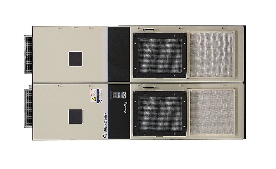
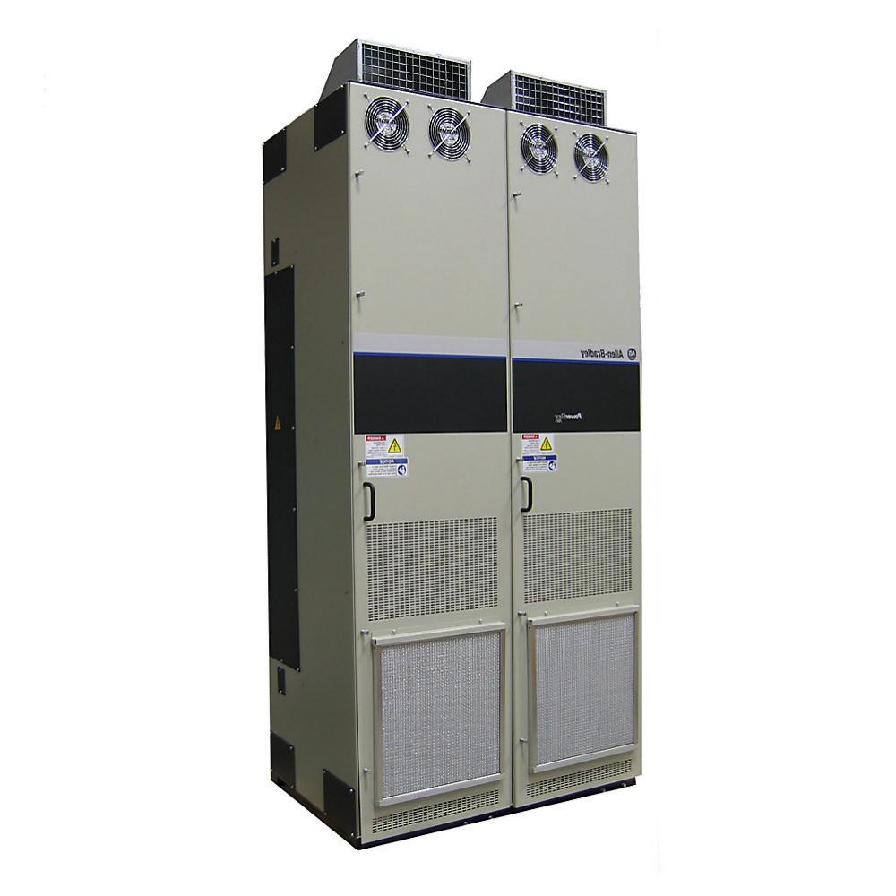
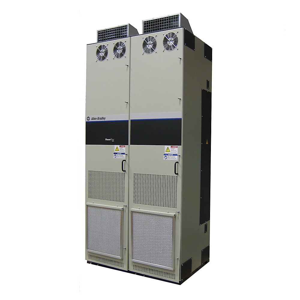
- Allen Bradley
- 20J1F3C2K1LNDNNNNN
- PowerFlex AC Drive
- USA
- 1,100–1,500 × 600–900 × 400–550 mm
- 220kg
- Xiamen, China
- New & In Stock
- T/T, PayPal, Western Union
- 1 Year
- 1-3 Working Days
- DHL, UPS, TNT, FedEx and EMS.
- 24-Hour Service
- COO
- 3
Our advantage

Global Logistics
We have a 10-year logistics and express cooperation agreement, so our products can be shipped to any place in the world.

Brand new and original
Our products are imported in bulk from the place of origin. Because of the cooperative relationship, our products are all original and 100% new.

24-hour service
We provide 7*24 hours service to our customers. We will be there whenever you need us.

Price advantage
All our products are priced very favorably because we have our own warehouse and supply.
| Company Information | |||
| [email protected] | |||
| Mobile | +8615980777398 | ||
| +8615980777398 | |||
| 15980777398 |
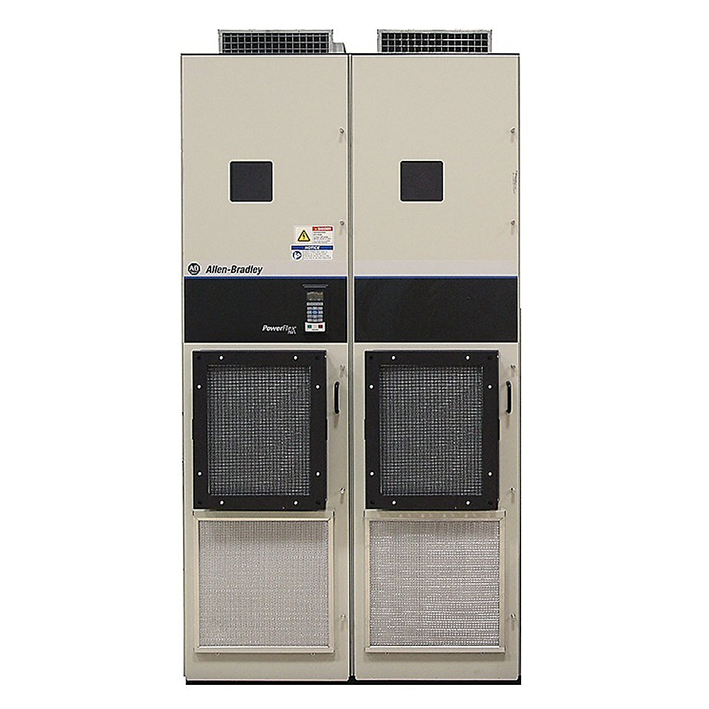
Allen-Bradley 20J1F3C2K1LNDNNNNN PowerFlex 750 Bus Supply
1. Product Overview
The Allen-Bradley 20J1F3C2K1LNDNNNNN is an air-cooled PowerFlex 750 Bus Supply designed for high-power industrial drive systems that use a common DC-bus architecture.
It belongs to the PowerFlex 750 Bus Supply family and is intended to provide controlled electrical power to the DC bus of a coordinated drive system. Catalog listings identify the exact model as an Air Cooled 750 Bus Supply, while closely related catalog numbers include other C2K1 configurations and larger or smaller members of the same 20J1F3 family.
Unlike a conventional variable-frequency drive, the 20J1F3C2K1LNDNNNNN is primarily a bus-power component. Its job is to establish and manage the electrical DC-bus supply used by compatible drive sections and connected motor-control equipment.
This type of architecture is particularly useful for large machines with several coordinated motors, substantial regenerative energy, frequent acceleration and deceleration, or a requirement for centralized power management.
The model is therefore most appropriately considered a high-power front-end and DC-bus supply component within a larger PowerFlex industrial automation system.
2. Basic Product Parameters
| Parameter | Specification |
|---|---|
| Brand | Allen-Bradley |
| Model | 20J1F3C2K1LNDNNNNN |
| Product Family | PowerFlex 750 |
| Product Series | PowerFlex 750 Bus Supply |
| Product Type | Air-Cooled 750 Bus Supply |
| Main Function | DC-bus power supply |
| Architecture | PowerFlex 750 system architecture |
| Input Configuration | Industrial AC front-end |
| Voltage Class | 400 V AC class |
| Cooling Method | Air cooled |
| Installation | Industrial cabinet / drive system |
| Application | Common DC-bus and high-power drive systems |
| Regenerative Application | Suitable for systems requiring regenerative energy management |
| Mounting | Industrial equipment / cabinet integration |
| Approx. Dimensions | 1,100–1,500 mm H × 600–900 mm W × 400–550 mm D* |
| Approx. Weight | 140–220 kg* |
| Product Category | High-power bus supply |
| Typical System | Multi-drive / common DC bus |
| Catalog Family | 20J1F3 |
| Configuration Suffix | LNDNNNNN |
| Service Requirement | High-voltage industrial maintenance procedures |
*Dimensions and weight are engineering planning estimates, not certified mechanical-drawing values for the exact configured unit. Final cabinet design, transportation planning, lifting equipment selection, and floor-loading calculations should be based on the actual product drawing and nameplate.
3. Brand
Brand: Allen-Bradley
Allen-Bradley is the brand associated with the PowerFlex industrial drive portfolio.
For industrial documentation, purchasing records, equipment lists, and maintenance databases, the complete catalog number 20J1F3C2K1LNDNNNNN should be retained rather than shortening the model number.
4. Product Series
Series: PowerFlex 750 Bus Supply
The 20J1F3C2K1LNDNNNNN belongs to the PowerFlex 750 Bus Supply family.
The 20J1F3 family includes a range of air-cooled bus-supply configurations. Catalog listings show closely related models such as 20J1F3C1K2LNDNNNNN, 20J1F3C1K4LNDNNNNN, 20J1F3C2K8LNDNNNNN, 20J1F3C302LNANNNNN, 20J1F3C367LNDNNNNN, 20J1F3C540LNANNNNN, 20J1F3C650LNANNNNN, and larger C/D-family configurations.
This makes the 20J1F3C2K1LNDNNNNN part of a broad high-power bus-supply range rather than an isolated product.
5. What the 20J1F3C2K1LNDNNNNN Does
A conventional variable-frequency drive normally converts incoming AC power into controlled AC output for a motor.
A bus supply has a different purpose.
The bus supply establishes the DC power source used by connected drive sections. In a multi-drive machine, several individual motor-control sections can share a common DC-bus architecture.
This arrangement can provide a more centralized approach to power conversion.
Instead of treating every motor as a completely independent electrical system, the machine can be designed around a coordinated DC-bus structure.
That approach becomes particularly useful when several motors operate simultaneously and when one motor may be consuming electrical energy while another motor is returning energy during braking or deceleration.
6. 400 V AC Industrial Class
The F3 configuration is associated with the 400 V AC industrial class within this bus-supply family.
This voltage class is widely used in industrial manufacturing and process facilities.
Typical installations may use a three-phase plant distribution system feeding the bus supply through appropriate upstream protection and switching equipment.
Before installation, the actual plant voltage, frequency, transformer capacity, short-circuit rating, grounding system, and protection arrangement must be checked against the complete system design.
7. Air-Cooled Construction
The 20J1F3C2K1LNDNNNNN is identified as an Air Cooled 750 Bus Supply.
Air cooling is a practical approach for large industrial power-conversion equipment.
There is no requirement for a separate liquid-cooling circuit, pump system, coolant reservoir, or external heat exchanger.
However, air cooling does not mean that thermal design can be ignored.
The cabinet must provide sufficient ventilation, and the installation must account for heat generated by the bus supply and all adjacent electrical equipment.
Particular attention should be given to:
- Cabinet airflow.
- Cooling-fan operation.
- Air inlet and outlet clearance.
- Ambient temperature.
- Dust accumulation.
- Oil mist.
- Humidity.
- Corrosive atmosphere.
- Installation altitude.
- Heat generated by nearby drives.
- Service access around cooling components.
8. Common DC-Bus Architecture
One of the main reasons to use a PowerFlex bus supply is the ability to build a common DC-bus system.
In a common DC-bus installation, multiple drive sections can be connected to a shared electrical bus.
This can be useful when motors are mechanically or operationally related.
For example, a production line may contain several motors controlling:
- Conveyor sections.
- Rollers.
- Winders.
- Unwinders.
- Hoists.
- Feed systems.
- Positioning axes.
- Process sections.
- Material-handling mechanisms.
The bus supply becomes the central electrical power source for the coordinated drive system.
9. Regenerative Energy Management
Regenerative operation occurs when a motor or mechanical load returns energy to the electrical system.
This can happen during:
- Deceleration.
- Lowering operations.
- Braking.
- Overhauling loads.
- High-inertia stopping.
- Tension-control operations.
- Vertical movement.
- Rapid speed reduction.
In a conventional system, regenerative energy may require braking resistors or another dedicated energy-management arrangement.
A coordinated bus-supply architecture can instead be designed to manage regenerated energy at the system level.
This can be particularly valuable in machines that repeatedly accelerate and decelerate throughout every production cycle.
10. Main Applications
Heavy-Duty Conveyors
Large conveyors can contain multiple motors distributed across a long mechanical system.
A common DC-bus arrangement allows the individual drive sections to operate as part of a coordinated electrical system.
This is useful for long-distance conveying, bulk-material handling, production lines, and high-inertia conveyor systems.
Cranes
Crane applications are one of the most demanding environments for electrical drive systems.
During lifting, electrical power flows toward the motor.
During lowering, the motor can enter a regenerative operating condition.
A high-power bus-supply architecture can therefore be useful for cranes where power flow changes direction frequently.
Hoisting Systems
Hoists experience frequent acceleration, deceleration, lifting, and lowering cycles.
The electrical system must therefore accommodate both motoring and regenerative conditions.
The 20J1F3C2K1LNDNNNNN can be considered for high-power hoisting systems where a coordinated PowerFlex DC-bus architecture is required.
Elevators and Vertical Motion
Vertical-motion systems can generate significant regenerative energy.
When a load moves downward under controlled braking, mechanical energy is returned to the motor.
That energy becomes electrical energy and must be managed by the drive system.
A common DC-bus architecture can provide a centralized way to handle this type of operating condition.
Winding and Unwinding Machines
Winders and unwinders frequently accelerate, decelerate, and maintain controlled tension.
The motors can alternate between motoring and generating operation.
A centralized DC-bus system can be useful for coordinating several drive sections in such machinery.
Test Stands
Industrial test stands and dynamometers frequently operate through repeated acceleration and deceleration cycles.
The amount of regenerative energy can be substantial.
A PowerFlex bus-supply architecture can therefore be considered where the test system needs coordinated power management between multiple motor sections.
Large Machine Tools
Large machine tools may contain several high-power motor systems.
A common DC-bus approach can be advantageous when several motor sections need to operate as one coordinated machine.
The final selection should be based on the machine’s power, braking profile, duty cycle, and DC-bus requirements.
Process Lines
Continuous manufacturing lines often contain many motors distributed across multiple sections.
A common bus architecture can help organize the power system around a centralized electrical structure.
This can be particularly useful where synchronization between drive sections is important.
11. Product Advantages
11.1 Common DC-Bus Capability
The most important advantage of the 20J1F3C2K1LNDNNNNN is its role as a high-power bus-supply component.
It is intended for systems where multiple drive sections can share a coordinated DC-bus architecture.
This makes it particularly appropriate for large machines rather than small standalone motor applications.
11.2 Centralized Power Architecture
A centralized bus supply can simplify the overall electrical concept of a multi-drive machine.
Instead of designing every motor drive as a completely independent power system, the machine can use a common power architecture.
11.3 Regenerative Energy Management
For machines with frequent braking, a common DC-bus system can provide a more organized way to manage regenerated electrical energy.
The exact energy-saving benefit depends on the machine’s duty cycle and the amount of energy actually regenerated.
11.4 Air-Cooled Design
The air-cooled construction provides a relatively straightforward thermal-management concept.
There is no requirement for a separate liquid-cooling infrastructure.
This can simplify installation and long-term maintenance when the cabinet ventilation system is correctly designed.
11.5 High-Power Industrial Applications
The PowerFlex 750 bus-supply family is intended for applications beyond ordinary small-motor VFD installations.
It is particularly relevant to large industrial machinery with substantial power requirements and coordinated motor operation.
11.6 Modular System Concept
A bus-supply architecture allows the machine designer to separate the power-supply function from the individual motor-control functions.
This can make the electrical system easier to organize when several drive sections are required.
11.7 Suitable for Coordinated Drives
The common-bus concept is particularly useful when several motors must accelerate, decelerate, or operate together.
This is common in production lines, material-handling equipment, winding machinery, and large automated machines.
12. Detailed Parameter Table
| Technical Parameter | 20J1F3C2K1LNDNNNNN |
|---|---|
| Brand | Allen-Bradley |
| Series | PowerFlex 750 |
| Family | PowerFlex 750 Bus Supply |
| Model | 20J1F3C2K1LNDNNNNN |
| Product Description | Air-Cooled 750 Bus Supply |
| Product Category | Industrial DC-bus power supply |
| Input Voltage Class | 400 V AC |
| Input Type | Industrial AC front-end |
| Cooling | Air cooled |
| System Architecture | Common DC bus |
| Main Function | DC-bus power supply |
| Regenerative Application | Yes, suitable for regenerative drive systems |
| Installation | Industrial cabinet |
| Application Type | Multi-drive system |
| Duty | Heavy industrial |
| Mechanical Form | Enclosure-mounted power equipment |
| Approx. Height | 1,100–1,500 mm* |
| Approx. Width | 600–900 mm* |
| Approx. Depth | 400–550 mm* |
| Approx. Weight | 140–220 kg* |
| Service Access | Front/service clearance required |
| Thermal Management | Forced-air cooling |
| Recommended Use | High-power industrial drive systems |
*Estimated engineering range. Confirm final dimensions and mass using the actual configuration drawing before fabrication or installation.
13. Mechanical Installation
The physical installation of the 20J1F3C2K1LNDNNNNN should be planned around both electrical and thermal requirements.
The equipment requires adequate clearance for airflow and maintenance.
The cabinet should provide enough room for power cabling, bus connections, grounding conductors, ventilation, and service access.
The estimated dimensions for preliminary planning are approximately:
Height: 1,100–1,500 mm
Width: 600–900 mm
Depth: 400–550 mm
Weight: approximately 140–220 kg
These figures are intended for preliminary equipment-layout work only.
The actual dimensions can vary according to the complete configured assembly, accessories, enclosure arrangement, and installation hardware.
For transportation, the actual equipment weight should be verified before selecting a forklift, crane, lifting beam, or other handling equipment.
14. Electrical System Design
A complete installation normally includes more than the bus supply itself.
A typical high-power system may contain:
- Incoming disconnect.
- Circuit protection.
- Main contactor or switching equipment.
- AC line components.
- Bus supply.
- DC-bus distribution.
- Individual drive sections.
- Motor cables.
- Grounding network.
- Control system.
- Safety circuit.
- Communication network.
- Cabinet cooling system.
- Auxiliary control power.
- Measurement and monitoring equipment.
The final arrangement depends on the machine architecture and applicable electrical standards.
15. Recommended Engineering Checks
Before replacing or specifying the 20J1F3C2K1LNDNNNNN, the following information should be checked.
| Engineering Check | Why It Matters |
|---|---|
| Incoming AC voltage | Confirms electrical compatibility |
| Frequency | Confirms supply compatibility |
| Transformer size | Ensures adequate source capacity |
| Short-circuit current | Determines protection requirements |
| Connected DC-bus load | Determines bus-supply suitability |
| Regenerative power | Determines energy-management requirements |
| Motor quantity | Determines system architecture |
| Motor power | Determines overall drive-system loading |
| Peak acceleration | Determines transient power demand |
| Deceleration profile | Determines regenerative energy |
| Cabinet dimensions | Confirms mechanical fit |
| Cabinet ventilation | Confirms thermal performance |
| Ambient temperature | Affects thermal capability |
| Altitude | May affect cooling and electrical ratings |
| Cable arrangement | Affects voltage drop and EMC |
| Grounding | Required for safe operation |
| Maintenance clearance | Required for service work |
| Replacement compatibility | Prevents incorrect substitution |
16. Five Closely Related Models
The following five models are suitable as comparison points within the same PowerFlex 750 Bus Supply family. They are not automatically interchangeable with the 20J1F3C2K1LNDNNNNN; the exact voltage, current, configuration, options, and mechanical arrangement must be checked before substitution. Catalog listings identify these as PowerFlex 750 or air-cooled 750 bus-supply configurations.
| Model | Product Type | Voltage Class | Cooling | Relative Power Class | Typical Application |
|---|---|---|---|---|---|
| 20J1F3C1K2LNDNNNNN | PowerFlex 750 Bus Supply | 400 V AC class | Air cooled | Lower than C2K1 configuration | Medium/high-power DC bus |
| 20J1F3C1K4LNDNNNNN | PowerFlex 750 Bus Supply | 400 V AC class | Air cooled | Lower/high-power comparison | Common DC-bus systems |
| 20J1F3C2K8LNDNNNNN | PowerFlex 750 Bus Supply | 400 V AC class | Air cooled | Higher than C2K1 configuration | Large industrial systems |
| 20J1F3C302LNANNNNN | PowerFlex 750 Bus Supply | 400 V AC class | Air cooled | High-power class | Large regenerative systems |
| 20J1F3C367LNDNNNNN-C1 | PowerFlex 750 Bus Supply | 400 V AC class | Air cooled | High-power class | Industrial common DC bus |
The C2K1, C2K8, C302, and C367 catalog numbers demonstrate that the 20J1F3 family covers a broad range of bus-supply configurations. The suffixes should be treated as significant configuration information rather than cosmetic model-number differences.
17. Five Additional Same-Brand PowerFlex Models
For a broader equipment comparison, the following models represent other commonly encountered members of the same PowerFlex product ecosystem.
| Model | Product Family | Product Type | Electrical Class | Cooling | Typical Application |
|---|---|---|---|---|---|
| 20F11FD096JA0NNNNN | PowerFlex 753 | AC Drive | Industrial AC | Air cooled | General industrial motor control |
| 20F11FD2P1AA0NNNNN | PowerFlex 753 | AC Drive | Industrial AC | Air cooled | Pumps, fans, conveyors |
| 20G14NE242JN0NNNNN | PowerFlex 755 | AC Drive | Industrial AC | Air cooled | High-performance motor control |
| 20G14NE289JN0NNNNN | PowerFlex 755 | AC Drive | Industrial AC | Air cooled | Process and machinery applications |
| 20G1G4F920MNDNNNNN | PowerFlex 755 | AC Packaged Drive | 690 V AC class | Air cooled | Large high-power machinery |
These are useful comparison products because the PowerFlex 753 and PowerFlex 755 families are designed for industrial AC-drive applications, while the 20J1 family is focused on bus-supply functionality. Catalog listings identify the examples above as PowerFlex 753, PowerFlex 755, or PowerFlex 755 AC packaged-drive products.
18. Comparison With a Conventional PowerFlex Drive
The distinction between a bus supply and an AC motor drive is important.
| Feature | 20J1F3C2K1LNDNNNNN | Conventional PowerFlex AC Drive |
|---|---|---|
| Primary Function | DC-bus power supply | Motor speed and torque control |
| Main Output | DC bus | Controlled AC motor output |
| Common DC Bus | Core application | Optional/system dependent |
| Regeneration | Important system function | Depends on configuration |
| Multi-Motor Architecture | Highly suitable | Depends on system |
| Motor Connection | Through compatible drive sections | Direct motor connection |
| Installation | System-level component | Individual or system drive |
| Power Architecture | Centralized | Usually decentralized |
| Typical Machine Size | Large | Small to large |
| Engineering Scope | Complete drive system | Individual drive/application |
19. Industrial Advantages at System Level
The biggest advantage of the 20J1F3C2K1LNDNNN architecture is not simply the bus supply itself.
The real benefit comes from using it as part of a coordinated drive system.
When several motors operate in the same machine, the electrical energy generated by one section may occur at the same time another section requires electrical power.
A common DC-bus architecture can therefore make the overall system more coordinated.
This is especially relevant in machines where the operating sequence contains frequent acceleration, deceleration, lifting, lowering, tension control, and speed changes.
20. Typical Machine Architecture
A typical high-power application can be conceptually organized as follows:
Incoming AC Power
↓
Protection and Switching
↓
20J1F3C2K1LNDNNNNN Bus Supply
↓
Common DC Bus
↓
Drive Section 1
↓
Motor 1
Drive Section 2
↓
Motor 2
Drive Section 3
↓
Motor 3
Drive Section 4
↓
Motor 4
This type of arrangement is particularly useful when multiple motors are mechanically or operationally connected.
21. Applications by Industry
| Industry | Example Equipment | Reason for Using a Bus Supply |
|---|---|---|
| Material Handling | Conveyors, transfer systems | Coordinated multi-drive power |
| Mining | Large conveyors, crushers | High-power drive architecture |
| Metals | Rolling and processing lines | Multiple coordinated motors |
| Paper | Winders and unwinders | Regenerative operation |
| Printing | Roll handling systems | High-speed coordinated motion |
| Ports | Cranes and hoists | Frequent regeneration |
| Manufacturing | Production lines | Centralized drive power |
| Automotive | Test and production equipment | Multi-drive coordination |
| Packaging | High-speed production lines | Coordinated motor control |
| Process Industry | Large rotating equipment | Centralized power management |
22. Maintenance Recommendations
Maintenance should be planned around the actual operating environment.
Cooling fans and airflow paths should be inspected regularly.
Dust accumulation can reduce heat-transfer performance and increase operating temperature.
Power connections should be inspected for signs of overheating, discoloration, mechanical looseness, or other abnormal conditions.
The cabinet should be maintained in a clean and dry condition appropriate to the installation environment.
Grounding connections should be maintained according to the electrical design.
Because the equipment forms part of a high-voltage DC-bus system, maintenance personnel must follow the complete lockout, isolation, discharge, and verification procedure applicable to the machine.
The DC bus must never be assumed to be safe simply because incoming AC power has been switched off.
23. Spare-Parts and Replacement Planning
For an industrial facility using this model, spare-parts planning should include more than simply keeping another bus-supply unit in storage.
A useful maintenance database should record:
- Complete catalog number.
- Equipment serial number.
- Installation location.
- Machine name.
- Incoming voltage.
- Connected drive configuration.
- DC-bus architecture.
- Cabinet identification.
- Cooling arrangement.
- Control-system configuration.
- Communication architecture.
- Replacement model information.
- Mechanical dimensions.
- Equipment weight.
- Installation drawing.
- Maintenance history.
24. Selection Notes for the C2K1 Configuration
The C2K1 portion of the catalog number should be retained when identifying the product.
It should not be replaced with a visually similar C2K8, C302, C367, or other configuration without checking the actual electrical ratings.
For large PowerFlex systems, the catalog-number suffix can identify meaningful configuration differences.
Two models may both be described as PowerFlex 750 bus supplies while having different power capabilities, options, protection arrangements, or mechanical configurations.
25. Mechanical Planning Table
| Mechanical Item | Preliminary Value |
|---|---|
| Height | 1,100–1,500 mm |
| Width | 600–900 mm |
| Depth | 400–550 mm |
| Approximate Weight | 140–220 kg |
| Cooling | Forced air |
| Mounting | Industrial cabinet |
| Front Access | Required |
| Cable Access | Allow sufficient working space |
| Ventilation | Required |
| Lifting | Industrial lifting equipment recommended |
| Floor Loading | Verify from actual installed weight |
| Final Drawing | Required before fabrication |
The dimensions and weight in this table are planning ranges rather than guaranteed catalog dimensions.
26. Product Advantages Summary
| Advantage | Description |
|---|---|
| Common DC Bus | Allows centralized power architecture |
| High-Power Capability | Intended for demanding industrial systems |
| Air Cooling | Practical industrial thermal-management approach |
| Regenerative Applications | Suitable for machines with significant regenerated energy |
| Multi-Drive Integration | Appropriate for coordinated drive systems |
| Centralized Power | Separates bus power from individual motor-control functions |
| Industrial Construction | Designed for demanding automation environments |
| Flexible System Architecture | Can support complex multi-motor machines |
| Maintenance Planning | Suitable for structured industrial service programs |
| PowerFlex Integration | Designed around the PowerFlex 750 architecture |
27. Product Identification Summary
| Item | Specification |
|---|---|
| Brand | Allen-Bradley |
| Product Series | PowerFlex 750 |
| Product Family | PowerFlex 750 Bus Supply |
| Full Model | 20J1F3C2K1LNDNNNNN |
| Description | Air-Cooled 750 Bus Supply |
| Voltage Class | 400 V AC |
| Cooling | Air cooled |
| Main Function | DC-bus power supply |
| Primary Application | High-power multi-drive systems |
| Regenerative Use | Yes |
| Approx. Dimensions | 1,100–1,500 × 600–900 × 400–550 mm |
| Approx. Weight | 140–220 kg |
| Installation | Industrial cabinet |
| Application Level | System-level power conversion |
28. Final Product Description
The Allen-Bradley 20J1F3C2K1LNDNNNNN is a high-power PowerFlex 750 Bus Supply intended for industrial drive systems that require centralized DC-bus power.
Its air-cooled construction makes it suitable for industrial cabinet installations where a properly engineered forced-air cooling arrangement is available.
The product is particularly relevant to machines containing several coordinated motors, especially where acceleration, deceleration, braking, lifting, lowering, winding, unwinding, or other regenerative operating conditions occur.
The common DC-bus architecture can provide a centralized electrical foundation for multiple compatible drive sections.
Compared with a conventional standalone variable-frequency drive, the 20J1F3C2K1LNDNNNNN should be viewed as a system-level power-conversion component rather than an individual motor controller.
The most important selection factors are the incoming AC voltage, complete DC-bus requirements, connected drive capacity, regenerative power, thermal conditions, mechanical installation space, protection system, and compatibility with the rest of the PowerFlex architecture.
For preliminary engineering, the unit can be planned around an approximate physical envelope of 1,100–1,500 mm high, 600–900 mm wide, and 400–550 mm deep, with an estimated equipment weight of approximately 140–220 kg.
Those mechanical figures are deliberately presented as estimates and should not be used as final cabinet-fabrication dimensions without confirmation from the actual equipment drawing.
Overall, the 20J1F3C2K1LNDNNNNN is best suited to large industrial automation systems where centralized DC-bus power, coordinated motor operation, and regenerative-energy management are more important than the simplicity of a single-motor AC drive.
For equipment identification, purchasing, maintenance, and replacement work, the complete catalog number should always be recorded as:
20J1F3C2K1LNDNNNNN
Brand: Allen-Bradley
Series: PowerFlex 750
Product: PowerFlex 750 Bus Supply
Configuration: Air Cooled
Voltage Class: 400 V AC
Primary Function: Common DC-bus power supply
Cooling: Air cooled
Approximate Weight: 140–220 kg
Approximate Dimensions: 1,100–1,500 × 600–900 × 400–550 mm