

ProductPRODUCT
Featured products
Contact Us
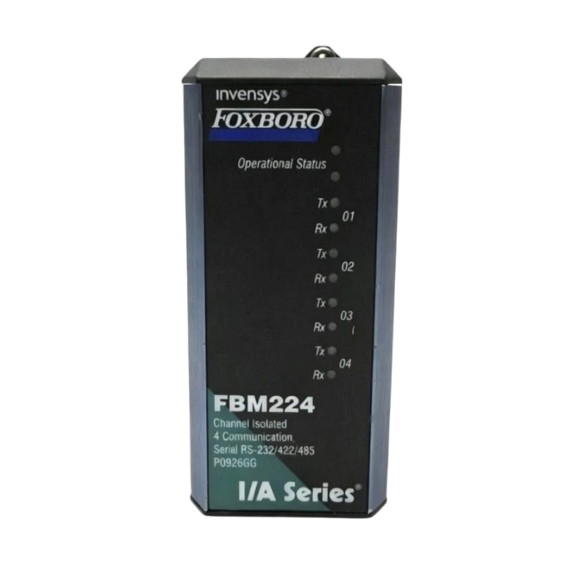
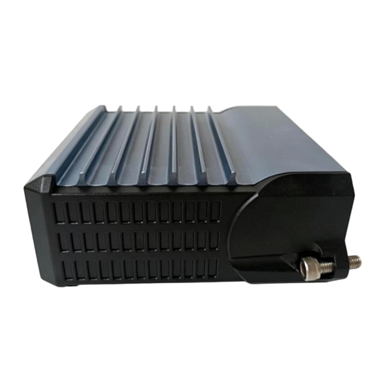
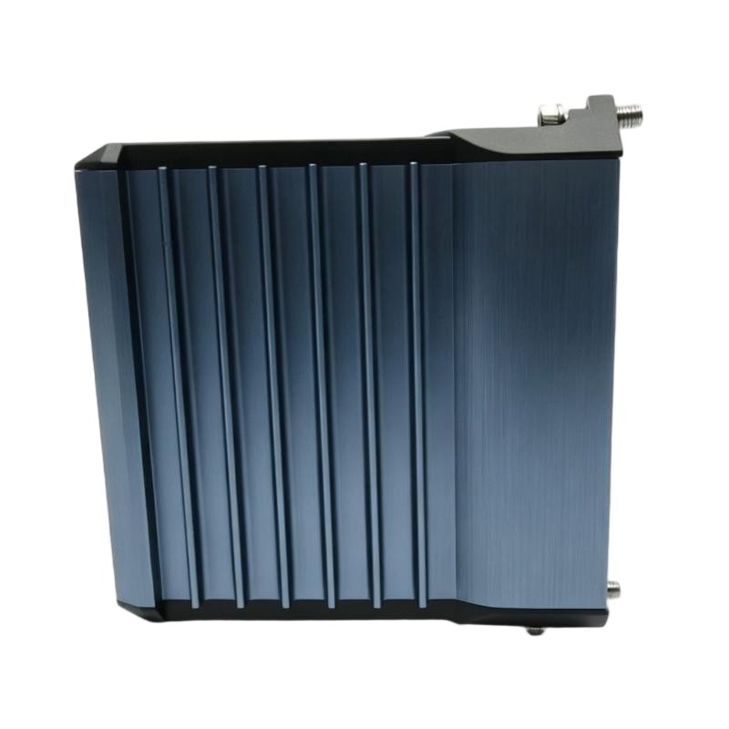
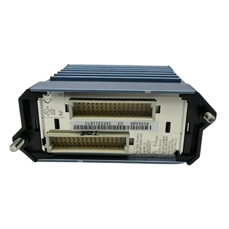
- Foxboro
- FBM224 P0926GG
- Modbus Communication Interface Module
- USA
- 114 × 45 × 104 mm
- 0.284 kg
- Xiamen, China
- New & In Stock
- T/T, PayPal, Western Union
- 1 Year
- 1-3 Working Days
- DHL, UPS, TNT, FedEx and EMS.
- 24-Hour Service
- COO
- 5
Our advantage

Global Logistics
We have a 10-year logistics and express cooperation agreement, so our products can be shipped to any place in the world.

Brand new and original
Our products are imported in bulk from the place of origin. Because of the cooperative relationship, our products are all original and 100% new.

24-hour service
We provide 7*24 hours service to our customers. We will be there whenever you need us.

Price advantage
All our products are priced very favorably because we have our own warehouse and supply.
| Company Information | |||
| [email protected] | |||
| Mobile | +8615980777398 | ||
| +8615980777398 | |||
| 15980777398 |
Product Overview
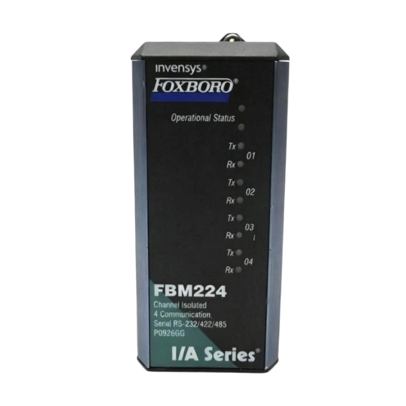
The Foxboro FBM224 P0926GG is an I/A Series Modbus communication interface module used to connect Modbus-compatible equipment with the Foxboro control system. It provides a communication interface between external devices using Modbus and the I/A Series control architecture, allowing data from distributed equipment to be incorporated into the plant control and monitoring environment.
Modbus is commonly used to exchange registers, status information, measurements, commands, and diagnostic data between automation equipment. In an I/A Series installation, the FBM224 provides the communication layer required to bring this information into the control system without requiring every data point to be connected as an individual hardwired signal.
The module is suited to applications involving third-party equipment or distributed automation devices that communicate through Modbus. Typical equipment may include meters, drives, controllers, packaged systems, and other intelligent devices. The FBM224 therefore helps integrate equipment from different parts of a plant into a common Foxboro control architecture.
Technical Specifications
| Parameter | Specification |
|---|---|
| Product Model | FBM224 P0926GG |
| Product Type | Modbus Communication Interface Module |
| Product Family | Foxboro I/A Series |
| Series | I/A Series |
| Communication Protocol | Modbus |
| Primary Function | Modbus Field Communication Interface |
| Communication Type | Digital Serial Communication |
| System Role | Modbus-to-Control-System Interface |
| Connected Equipment | Modbus-Compatible Devices |
| Typical Data | Measurements, Status, Registers, Commands, Diagnostics |
| Application | Third-Party Equipment and Distributed Automation Integration |
| Network Function | Digital Data Exchange |
| Installation | I/A Series I/O Cabinet / Communication Interface Assembly |
| Dimensions | 114 × 45 × 104 mm |
| Weight | 0.284 kg |
Product Features
- Provides Modbus communication interfacing within the Foxboro I/A Series architecture.
- Connects Modbus-compatible third-party equipment with the control system.
- Supports digital exchange of process, equipment, and status information.
- Reduces the need to hardwire every integrated data point individually.
- Suitable for meters, drives, packaged equipment, controllers, and other intelligent devices.
- Provides a defined communication interface between external equipment and the I/A Series environment.
- Supports centralized monitoring of distributed Modbus equipment.
- Fits established Foxboro I/A Series installations requiring integration with external automation devices.
Working Principle
The FBM224 P0926GG operates as a communication interface between Modbus-compatible equipment and the Foxboro I/A Series control environment.
1. External equipment generates data
A connected Modbus device produces information such as measured values, operating status, alarms, diagnostic information, or other configured data. The available data depends on the device and its Modbus register map.
2. Data is organized according to the Modbus configuration
The external device exposes its configured information through Modbus registers or communication objects. The communication arrangement determines which values are exchanged and how the I/A Series system interprets them.
3. FBM224 communicates with the Modbus device
The FBM224 provides the interface through which the Modbus data is exchanged with the external equipment. It handles the communication path rather than independently executing the process-control strategy.
4. Data enters the I/A Series architecture
The required information is made available to the control system, where configured points can represent measurements, equipment states, alarms, or other useful information from the external device.
5. Control applications use the exchanged data
The I/A Series control strategy can use the imported information for monitoring, sequencing, alarming, supervisory control, or equipment coordination. Where the configured communication arrangement permits data to be sent toward the external device, control or command information can also be exchanged through the same communication architecture.
The practical result is a digital data path between external Modbus equipment and the Foxboro control system, with the FBM224 serving as the interface layer.
Role in an I/A Series Modbus Communication Control Architecture
The FBM224 P0926GG occupies the communication interface layer between external Modbus equipment and the I/A Series control-processing environment. It allows information from independent automation devices to become part of the broader plant control and monitoring system.
| Architecture Layer | Typical Component | Role |
|---|---|---|
| Process Layer | Industrial Process Equipment | Performs or responds to the controlled process |
| Equipment Layer | Modbus-Compatible Device | Generates measurements, status, alarms, or command data |
| Communication Layer | Modbus Network | Transfers digital information between connected devices |
| Interface Layer | FBM224 P0926GG | Interfaces Modbus communication with the I/A Series system |
| Control Processing Layer | I/A Series Control Processor | Uses configured communication data in control strategies |
| Operator Layer | HMI / Operator Workstation | Displays integrated equipment information |
| Engineering Layer | Configuration and Diagnostic Tools | Supports communication configuration and troubleshooting |
Industrial Applications
| Application | Use of FBM224 P0926GG |
|---|---|
| Energy Monitoring | Integrates Modbus power meters and electrical monitoring equipment |
| Motor and Drive Systems | Exchanges drive status, operating values, and configured commands |
| Packaged Equipment | Connects third-party skids and packaged control systems to Foxboro |
| Water Treatment | Integrates Modbus instruments, controllers, and equipment packages |
| Chemical Processing | Brings distributed equipment data into the central control system |
| Oil and Gas Facilities | Supports integration of third-party automation equipment |
| Power Generation | Connects electrical and auxiliary equipment using Modbus |
| Manufacturing Plants | Provides centralized monitoring of networked automation devices |
Installation and Maintenance
- Verify that the FBM224 P0926GG is appropriate for the intended Foxboro I/A Series Modbus communication architecture before installation.
- Confirm the external Modbus devices, communication topology, and associated I/A Series configuration from the approved system documentation.
- Isolate the relevant communication and control equipment according to the plant’s electrical safety and maintenance procedures before replacing the module.
- Inspect communication connectors and associated wiring for loose connections, contamination, corrosion, or mechanical damage.
- Verify the Modbus device configuration, including the communication parameters required by the installed system.
- Confirm device addressing and the configured register or data mapping when communication is established but expected values are not appearing correctly.
- Check the complete communication path between the external device, Modbus network, FBM224, and I/A Series system before replacing hardware.
- Review the external device’s register map when a value is missing, incorrectly scaled, or associated with the wrong control-system point.
- Use available I/A Series and device diagnostics to distinguish between communication faults, configuration errors, wiring problems, and external-device faults.
- After replacing the module, verify communication with the affected Modbus equipment and confirm that the required data points are correctly updated.
- Monitor for intermittent communication failures, unexpected data dropouts, or unstable values that may indicate network or device-side problems.
- Record module replacement, communication parameters, device mapping changes, diagnostic results, and functional test results in the maintenance documentation.
Related Components
| Component | Function |
|---|---|
| Foxboro I/A Series Control Processor | Uses Modbus-derived information within configured control strategies |
| Modbus-Compatible Meter | Provides measurement and status data to the control system |
| Modbus Drive | Exchanges drive operating information and configured commands |
| Modbus Controller | Provides data from an independent automation or equipment-control system |
| Modbus Network Cabling | Provides the physical communication path |
| Modbus Network Devices | Connect external equipment to the communication network |
| Operator Workstation | Displays integrated equipment measurements, status, and alarms |
| Engineering and Diagnostic Tools | Support communication configuration, data mapping, and troubleshooting |
Recommended Related Models
| Model | Product Type | Typical Relationship |
|---|---|---|
| Foxboro FBM223 P0917HD | I/A Series PROFIBUS-DP Communication Interface Module | Related fieldbus communication interface |
| Foxboro FBM219 P0916RH | I/A Series Discrete I/O Interface Module | Related I/A Series I/O interface |
| Foxboro FBM218 P0922VW | I/A Series HART Communication Redundant Output Module | Related communication-capable output interface |
| Foxboro FBM216b P0927AJ | I/A Series HART Communication Redundant Input Module | Related digital communication input interface |
| Foxboro FBM217 P0916PW | I/A Series Discrete Input Interface Module | Related field input interface |
Key Advantages
- Provides Modbus connectivity within the Foxboro I/A Series architecture.
- Integrates third-party Modbus equipment into the control environment.
- Supports digital exchange of measurements, status, commands, and diagnostic information.
- Reduces dependence on individual hardwired connections for networked equipment.
- Suitable for distributed meters, drives, controllers, and packaged systems.
- Provides a structured communication path between external automation equipment and Foxboro control processing.
Technical FAQs
What is the purpose of the FBM224 P0926GG?
The FBM224 P0926GG provides a Modbus communication interface between compatible external equipment and the Foxboro I/A Series control system. It allows configured digital information from Modbus devices to be incorporated into the control and monitoring architecture.
What type of equipment can be integrated through the FBM224?
The module can be used with compatible Modbus equipment such as meters, drives, controllers, packaged systems, and other intelligent automation devices. The actual integration depends on the device’s Modbus implementation, communication configuration, and available data mapping.
Why might a Modbus device communicate but show incorrect values in the control system?
A communication link can be active even when the data mapping is incorrect. Register addressing, data type, register order, scaling, point assignment, and the external device’s register map should therefore be checked when the received value does not correspond to the actual equipment condition.
What should be checked when the FBM224 loses communication with an external device?
Start with the physical communication path and device status, then verify communication parameters, device addressing, network configuration, and the I/A Series point configuration. If the problem affects only one device, inspect that device and its local connection; if multiple devices are affected, examine the shared communication path and interface configuration.