

ProductPRODUCT
Featured products
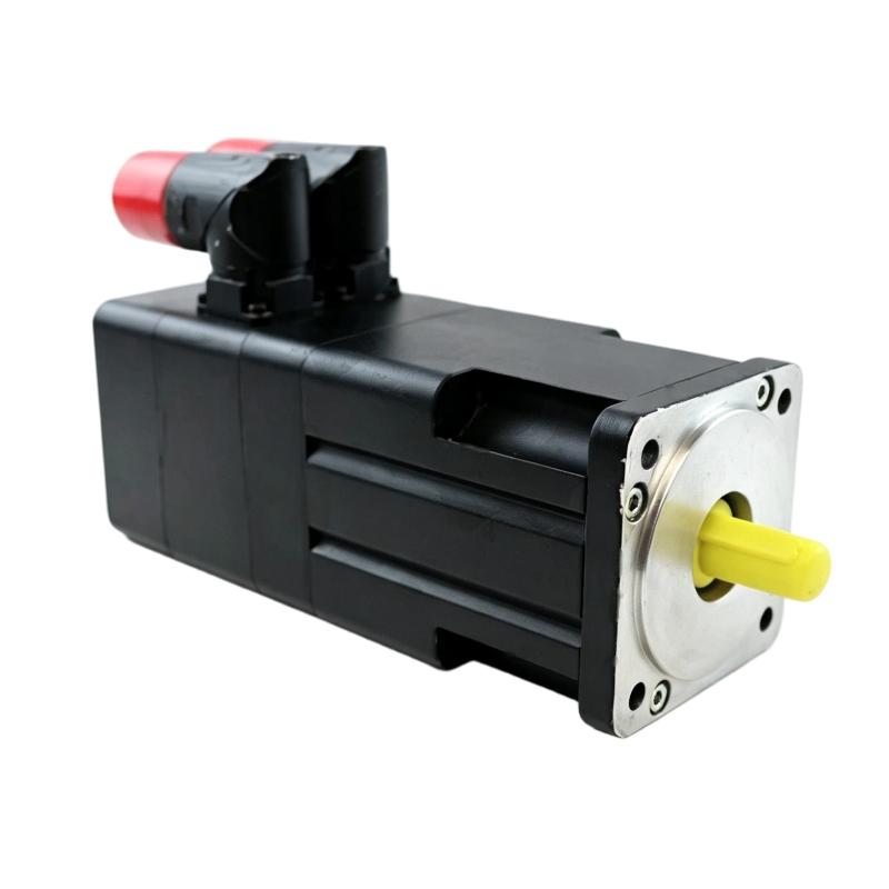
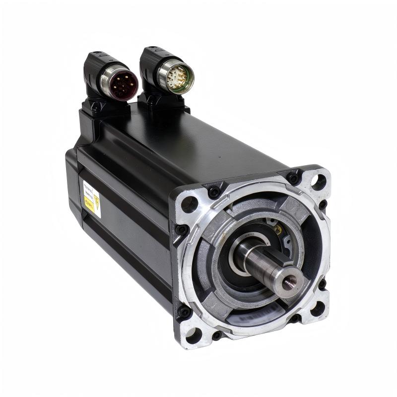
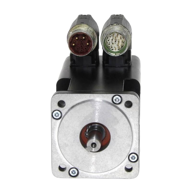
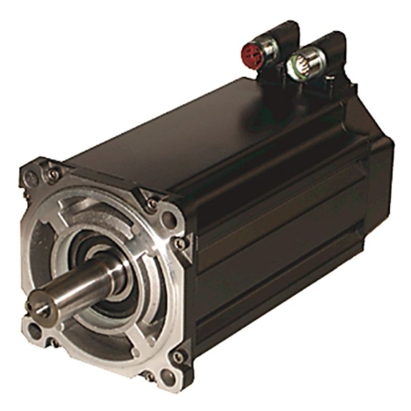
Contact Us
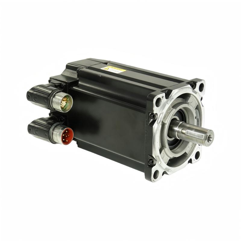
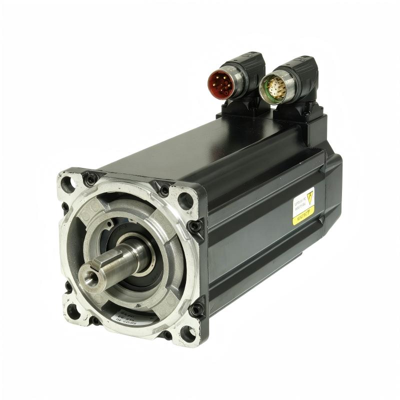
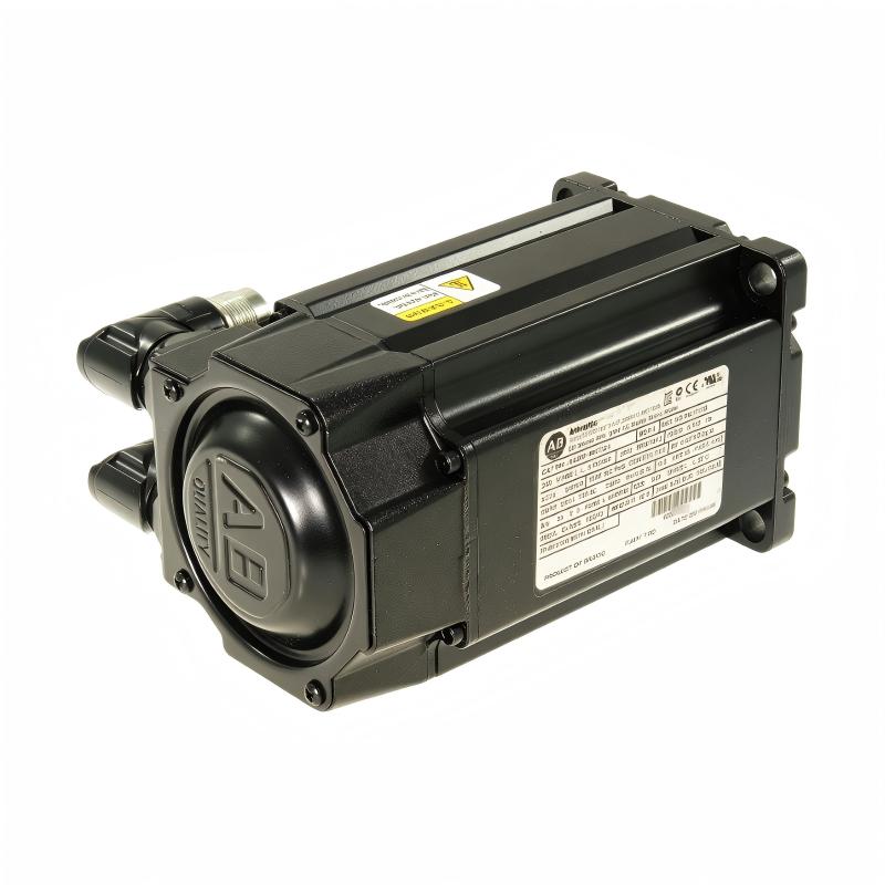
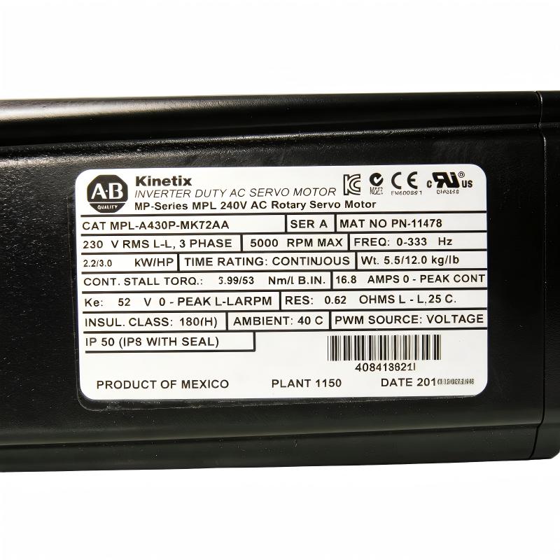
- Allen Bradley
- MPL-A430P-MK72AA
- Servo Motor
- USA
- 115 mm
- 5.5 kg
- Xiamen, China
- New & In Stock
- T/T, PayPal, Western Union
- 1 Year
- 1-3 Working Days
- DHL, UPS, TNT, FedEx and EMS.
- 24-Hour Service
- COO
- 4
Our advantage

Global Logistics
We have a 10-year logistics and express cooperation agreement, so our products can be shipped to any place in the world.

Brand new and original
Our products are imported in bulk from the place of origin. Because of the cooperative relationship, our products are all original and 100% new.

24-hour service
We provide 7*24 hours service to our customers. We will be there whenever you need us.

Price advantage
All our products are priced very favorably because we have our own warehouse and supply.
| Company Information | |||
| [email protected] | |||
| Mobile | +8615980777398 | ||
| +8615980777398 | |||
| 15980777398 |
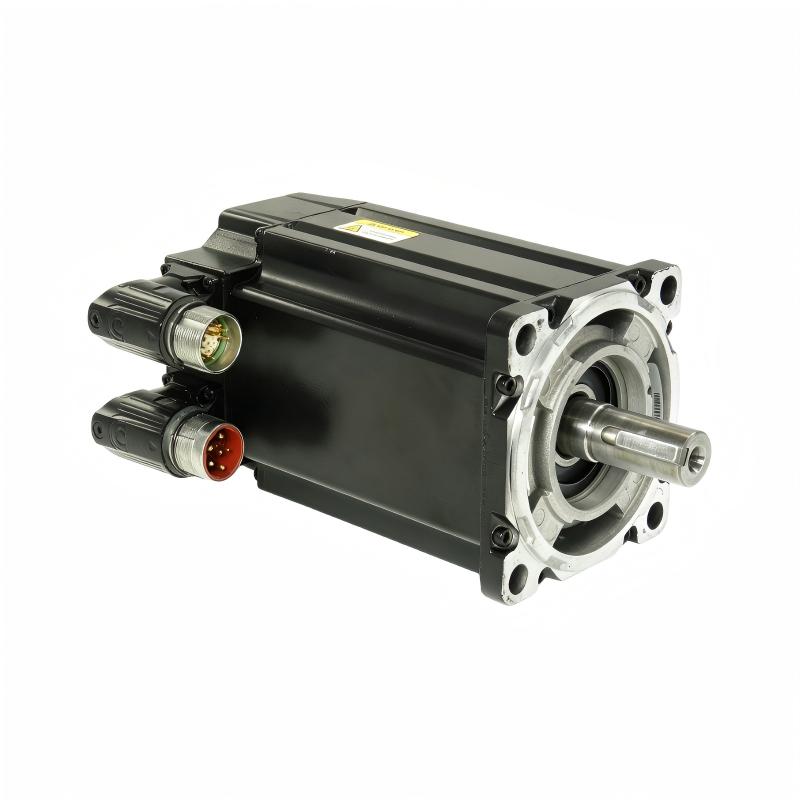
Product Overview
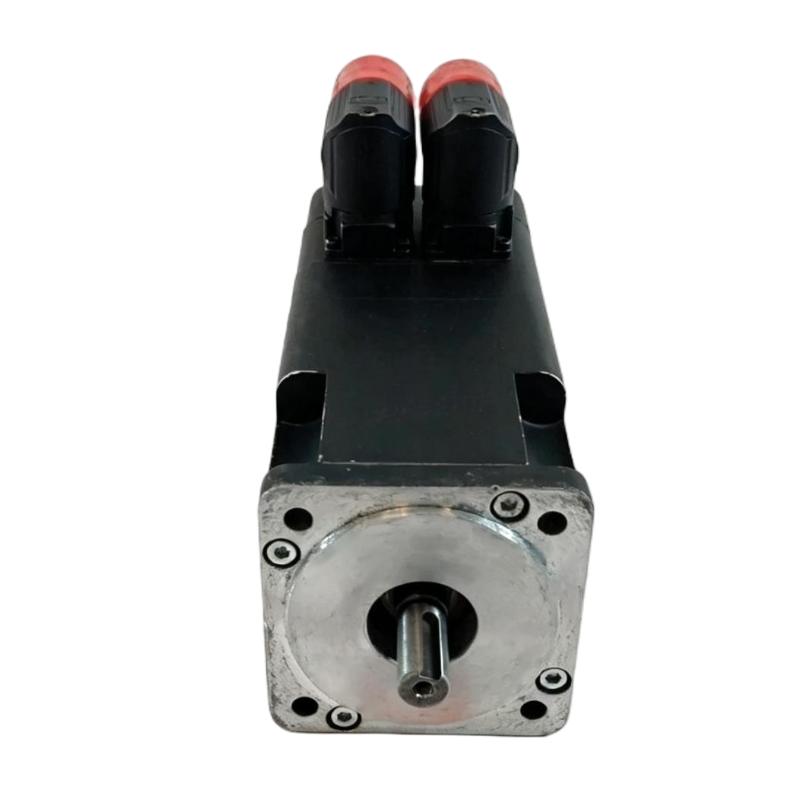
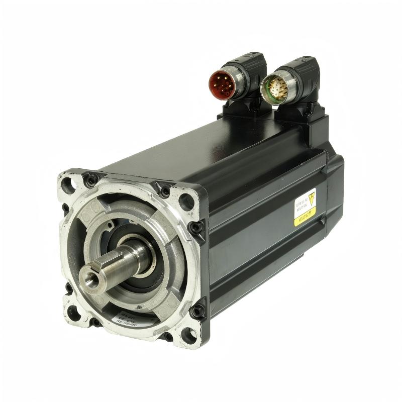
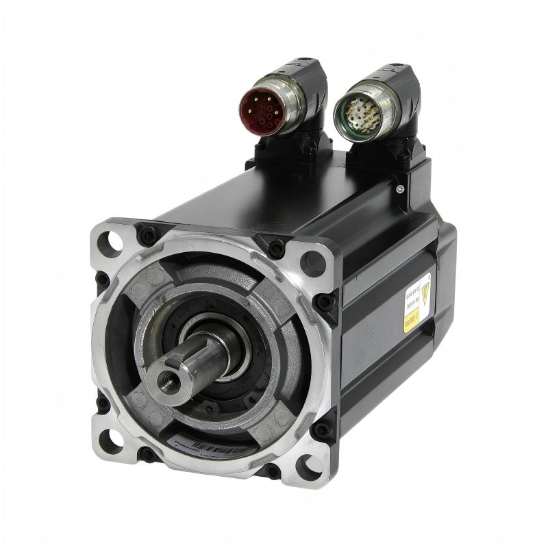
The Allen Bradley MPL-A430P-MK72AA Servo Motor is an industrial servo motor designed for integration into automated motion-control and machine automation systems. As part of the Allen Bradley MPL servo motor family, this motor is intended for applications that require controlled rotational movement, repeatable positioning, coordinated machine operation, and responsive motion performance.
A servo motor normally operates as one component of a complete motion-control system. The motion controller generates the desired movement, the servo drive controls the electrical power delivered to the motor, and the feedback system provides information about actual motor operation. This closed-loop architecture allows the machine to regulate movement according to programmed requirements.
The MPL-A430P-MK72AA has a specified 115 mm frame size and a weight of 5.5 kg. These specifications are important for machine design, mechanical mounting, installation planning, handling, and replacement logistics.
The exact electrical and performance characteristics of the motor should be verified against the specific motor nameplate and applicable documentation. Rated torque, speed, voltage, current, feedback type, shaft dimensions, connector arrangement, and other detailed specifications should not be assumed without confirmation.
Technical Specifications
| Parameter | Specification |
|---|---|
| Manufacturer | Allen Bradley |
| Product Family | MPL Servo Motor |
| Model | MPL-A430P-MK72AA |
| Product Type | Industrial Servo Motor |
| Application | Motion Control and Industrial Automation |
| Frame Size | 115 mm |
| Weight | 5.5 kg |
| Installation | Machine-mounted servo system |
| Control Architecture | Servo drive and motion controller |
| Feedback | Verify according to exact motor configuration |
| Rated Performance | Verify from motor nameplate and applicable documentation |
| Typical Applications | Automated machinery, positioning systems, manufacturing equipment, material handling |
The confirmed physical specifications supplied for the MPL-A430P-MK72AA are 115 mm frame size and 5.5 kg weight. Other electrical and mechanical parameters should be verified for the exact motor configuration.
What Is the Allen Bradley MPL-A430P-MK72AA?
The Allen Bradley MPL-A430P-MK72AA is a servo motor designed to provide controlled mechanical rotation within an industrial automation system.
Unlike a basic motor installation, a servo system uses coordinated control between the motor, servo drive, controller, and feedback system.
A simplified architecture is:
PLC / Motion Controller → Servo Drive → MPL-A430P-MK72AA Servo Motor → Mechanical Load
The feedback path can be represented as:
Motor / Feedback → Servo Drive / Controller → Motion Correction
This arrangement allows the machine to monitor actual movement and adjust motor operation according to the required motion profile.
The MPL-A430P-MK72AA can therefore serve as a motor element in automated axes where controlled movement and repeatability are important.
Servo Motor Working Principle
The operating principle of a servo system involves several coordinated stages.
Motion Command
The motion controller establishes the desired machine movement based on the application program.
The command may define position, velocity, acceleration, deceleration, or coordinated movement requirements.
Servo Drive Regulation
The servo drive receives the command and regulates the electrical power delivered to the motor.
The drive manages motor operation according to the configured control parameters and feedback information.
Mechanical Rotation
The MPL-A430P-MK72AA converts electrical energy into mechanical rotational movement.
The motor shaft transfers this movement to the machine through a suitable mechanical transmission.
Feedback-Based Correction
Actual motor movement is monitored through the applicable feedback arrangement.
The control system can compare actual behavior with the commanded motion and make corrections when required.
This closed-loop operation is a fundamental feature of industrial servo systems.
Main Functions
The MPL-A430P-MK72AA can support several important functions in an industrial motion-control system.
Controlled Rotation
The motor provides controlled mechanical rotation under the management of a compatible servo drive.
Positioning
Servo systems can move machine mechanisms toward programmed positions with repeatable operation.
Speed Regulation
The motor can participate in applications requiring controlled rotational speed.
Acceleration and Deceleration
Controlled motion profiles can provide smoother machine starts and stops.
Coordinated Motion
The motor can operate as one axis within a multi-axis motion-control system.
Repeatable Movement
Closed-loop servo operation supports consistent machine movement between production cycles.
Role in Industrial Automation
The MPL-A430P-MK72AA can function as the drive motor for an automated machine axis.
A complete motion system may include:
- PLC or motion controller
- Servo drive
- Servo motor
- Feedback system
- Mechanical transmission
- Machine load
- Operator interface
- Safety system
- Industrial communication network
The controller establishes the desired movement, the servo drive controls the motor, and the motor produces the required mechanical output.
This architecture allows servo motors to be integrated into machines requiring precise and repeatable motion.
Industrial Applications
Packaging Machinery
Packaging equipment often requires synchronized movement for feeding, indexing, cutting, sealing, and product positioning.
Servo motors can provide controlled movement for these processes.
Material Handling
Automated material-handling systems can use servo motors for positioning, transfer mechanisms, conveyors, and other controlled movement functions.
Assembly Machinery
Automated assembly systems often require coordinated motion between components, tools, and workpieces.
Manufacturing Equipment
Servo motors can be used in manufacturing machinery requiring repeatable mechanical movement.
Printing and Converting
Printing and converting machines can require synchronized motion between rollers, feeders, cutters, and other mechanisms.
Automated Positioning Systems
The motor can form part of an axis used to position machine components repeatedly.
General Industrial Automation
The MPL-A430P-MK72AA can be considered for general machine automation when the complete motor, drive, controller, feedback, and mechanical configuration are appropriately matched.
Mechanical Integration
The physical characteristics of the motor should be considered during machine design.
The specified 115 mm frame size provides a useful reference for evaluating mounting compatibility and available machine space.
Mechanical integration should consider:
- Motor mounting arrangement
- Mounting surface rigidity
- Shaft alignment
- Coupling selection
- Mechanical loading
- Installation clearance
- Cable routing
- Vibration
- Environmental conditions
- Maintenance access
The motor should be mounted securely to a rigid structure.
Proper shaft alignment is particularly important. Misalignment may increase vibration, mechanical loading, coupling wear, and stress on the driven equipment.
The specified 5.5 kg weight should also be considered when designing supports and planning motor handling.
Servo Drive Integration
The MPL-A430P-MK72AA should be integrated with a compatible servo drive based on the exact motor configuration.
Before commissioning, verify:
- Complete motor model
- Motor nameplate
- Servo drive compatibility
- Feedback configuration
- Motor cable
- Feedback cable
- Connector arrangement
- Axis parameters
- Controller configuration
- Safety requirements
The exact motor configuration should be correctly selected in the servo drive.
A different MPL model should not automatically be treated as an equivalent motor-drive combination.
Installation Guidelines
1. Verify the Motor Identification
Confirm the complete model:
Allen Bradley MPL-A430P-MK72AA
The complete suffix should match the machine documentation.
2. Inspect the Motor
Before installation, check for:
- Housing damage
- Connector damage
- Cable damage
- Corrosion
- Contamination
- Loose components
- Transportation damage
3. Prepare the Mounting Surface
The mounting surface should be clean, rigid, stable, and properly aligned.
The machine should provide sufficient space for the specified 115 mm frame size.
4. Mount the Motor
Secure the motor using suitable mounting hardware.
Avoid unnecessary force on the shaft, housing, connectors, or cables.
5. Connect the Mechanical Load
Install the appropriate coupling or mechanical transmission and verify shaft alignment.
6. Connect Electrical and Feedback Interfaces
Connect motor and feedback wiring according to the applicable system documentation.
Route cables to minimize mechanical damage and electrical interference.
7. Configure the Servo Drive
Select the correct motor configuration and verify the relevant feedback and axis parameters.
8. Perform an Initial Test
Run a controlled movement test and verify direction, response, acceleration, deceleration, vibration, noise, and drive status.
Commissioning Procedure
A structured commissioning procedure can reduce the risk of installation errors.
Mechanical Verification
Check motor mounting, shaft alignment, coupling, mechanical transmission, and clearances.
Electrical Verification
Verify motor connections, feedback connections, grounding, and cable routing.
Drive Configuration
Confirm that the servo drive is configured for the correct motor and feedback arrangement.
Controller Configuration
Verify axis assignment, motion commands, operating limits, and machine sequence.
Initial Enable
Enable the axis under controlled conditions.
Direction Test
Confirm that actual motor rotation corresponds to the intended machine direction.
Controlled Motion Test
Perform an initial low-risk movement test.
Functional Verification
Check positioning response, acceleration, deceleration, vibration, noise, and diagnostic information before normal production.
Troubleshooting
Servo problems should be diagnosed across the complete motion system.
Motor Does Not Rotate
Potential causes include:
- Servo drive disabled
- Drive fault
- Incorrect motor configuration
- Missing motion command
- Feedback problem
- Safety circuit active
- Motor cable issue
- Mechanical obstruction
Check controller and drive status before replacing the motor.
Incorrect Rotation Direction
Unexpected direction may result from controller configuration, axis parameters, wiring, or machine settings.
Verify the commanded direction and actual machine movement.
Excessive Vibration
Possible causes include:
- Shaft misalignment
- Coupling problems
- Incorrect mounting
- Mechanical resonance
- Excessive load
- Incorrect motion parameters
- Feedback-related problems
Inspect the mechanical system before assuming motor failure.
Positioning Error
Possible causes include:
- Servo tuning problems
- Controller configuration
- Mechanical backlash
- Coupling problems
- Excessive load
- Feedback issues
- Motion parameter errors
The complete motion axis should be evaluated.
Motor Overheating
Possible causes include excessive loading, insufficient cooling, unsuitable environmental conditions, mechanical resistance, or incorrect drive configuration.
The motor, drive, and machine load should be checked together.
Intermittent Faults
Intermittent problems may be related to:
- Loose connectors
- Damaged cables
- Feedback connections
- Electrical interference
- Mechanical vibration
- Drive configuration
- Environmental conditions
Inspect the complete power, feedback, and control paths.
Maintenance Recommendations
Regular maintenance can help maintain reliable servo operation.
Motor Inspection
Inspect the motor housing, mounting arrangement, connectors, and cables.
Mechanical Inspection
Check the coupling and driven equipment for wear, looseness, or alignment problems.
Cable Inspection
Inspect motor and feedback cables for abrasion, excessive bending, loose connections, or connector damage.
Drive Diagnostics
Review servo drive diagnostic information and fault history during maintenance.
Performance Monitoring
Monitor changes in vibration, noise, positioning behavior, and operating temperature.
Environmental Control
Maintain appropriate environmental conditions around the motor and associated equipment.
Physical Dimensions and Weight
The confirmed physical specifications supplied for the Allen Bradley MPL-A430P-MK72AA Servo Motor are:
- Frame Size: 115 mm
- Weight: 5.5 kg
The 115 mm frame size should be considered when evaluating machine mounting compatibility and available installation space.
The 5.5 kg weight is relevant to mechanical support, installation handling, transportation, and replacement planning.
Frame size does not represent the complete external dimensions of the motor. Exact overall length, shaft dimensions, mounting-hole arrangement, connector location, and other mechanical details should be verified from the applicable documentation.
Servo System Architecture
A typical motion-control system using the MPL-A430P-MK72AA can be represented as:
PLC / Motion Controller
↓
Motion Command
↓
Servo Drive
↓
MPL-A430P-MK72AA Servo Motor
↓
Mechanical Transmission
↓
Machine Load
Feedback information returns to the servo control system, allowing actual motor behavior to be monitored.
This architecture supports automated positioning, speed control, and coordinated machine movement.
Replacement Considerations
When replacing an existing motor, verify the complete MPL-A430P-MK72AA model designation.
Important identification information includes:
- Complete model number
- Frame size
- Motor nameplate
- Mechanical mounting
- Shaft configuration
- Feedback arrangement
- Connector configuration
- Motor cable
- Servo drive compatibility
- Controller configuration
- Machine load requirements
A motor should not be considered interchangeable simply because it belongs to the same MPL family or has a similar frame size.
The replacement must satisfy the requirements of the complete motion axis.
Engineering Best Practices
Match the Motor and Drive
Confirm that the servo drive supports the exact motor configuration.
Evaluate the Mechanical Load
Consider machine load, acceleration requirements, transmission characteristics, operating cycle, and mechanical inertia.
Maintain Shaft Alignment
Proper alignment reduces unnecessary mechanical stress and vibration.
Protect Feedback Wiring
Feedback cables should be routed and protected appropriately to reduce interference and physical damage.
Document Configuration
Maintain records of motor identification, drive parameters, controller configuration, and commissioning results.
Use Controlled Startup
Perform initial testing under controlled conditions before placing the machine into normal production.
Key Advantages
The Allen Bradley MPL-A430P-MK72AA Servo Motor offers characteristics suitable for industrial motion-control applications:
- 115 mm frame size
- 5.5 kg weight
- Industrial servo motor architecture
- Suitable for controlled rotational movement
- Suitable for automated positioning
- Supports closed-loop motion-control systems
- Can participate in coordinated multi-axis motion
- Suitable for manufacturing equipment
- Suitable for material-handling applications
- Applicable to general industrial automation
- Supports repeatable machine movement when correctly configured
Technical FAQs
What is the Allen Bradley MPL-A430P-MK72AA?
The Allen Bradley MPL-A430P-MK72AA is an MPL series industrial servo motor designed for automated motion-control applications.
What is the frame size?
The specified frame size is 115 mm.
What is the weight of the MPL-A430P-MK72AA?
The specified weight is 5.5 kg.
What is the primary function of this motor?
The motor converts controlled electrical power from a compatible servo drive into mechanical rotational movement for automated machinery.
Is the MPL-A430P-MK72AA part of a closed-loop motion system?
Servo motors are normally integrated into closed-loop systems involving a compatible servo drive, controller, and feedback arrangement.
What should be checked before installation?
The complete model number, frame size, mechanical mounting, shaft configuration, feedback arrangement, wiring, servo drive compatibility, and machine requirements should be verified.
What can cause servo positioning problems?
Possible causes include incorrect tuning, controller configuration, mechanical backlash, shaft misalignment, excessive loading, feedback problems, cable issues, or other motion-system conditions.
Is 115 mm the complete physical dimension of the motor?
No. The 115 mm specification identifies the frame size. Other dimensions must be verified separately.
Can another MPL motor replace the MPL-A430P-MK72AA?
Interchangeability should not be assumed based only on the product family or frame size. The complete model number and electrical, mechanical, feedback, and drive requirements should be verified.
Conclusion
The Allen Bradley MPL-A430P-MK72AA Servo Motor is an industrial motion-control motor designed to provide controlled mechanical rotation as part of an automated servo system. With a specified 115 mm frame size and 5.5 kg weight, it can be integrated into machinery requiring repeatable positioning, controlled movement, and coordinated machine operation.
The motor works together with a compatible servo drive, motion controller, feedback system, and mechanical load. Proper mechanical alignment, correct drive configuration, reliable feedback connections, and controlled commissioning are essential for stable operation.
For installation or replacement, the complete MPL-A430P-MK72AA model designation should be verified carefully. Exact electrical characteristics, feedback configuration, shaft arrangement, and drive compatibility should be confirmed before commissioning to ensure correct integration into the intended industrial automation system.