

ProductPRODUCT
Featured products



Contact Us
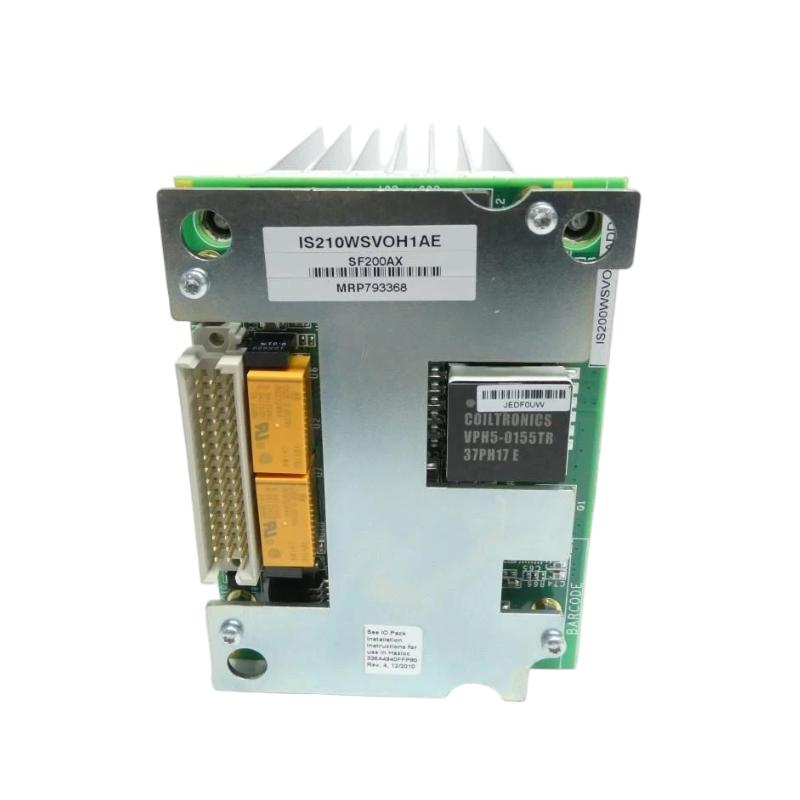
- GE
- IS210WSVOH1AE
- Circuit Board Heatsink Assembly
- USA
- 280 × 150 × 35 mm
- 0.55 kg
- Xiamen, China
- New & In Stock
- T/T, PayPal, Western Union
- 1 Year
- 1-3 Working Days
- DHL, UPS, TNT, FedEx and EMS.
- 24-Hour Service
- COO
- 4
Our advantage

Global Logistics
We have a 10-year logistics and express cooperation agreement, so our products can be shipped to any place in the world.

Brand new and original
Our products are imported in bulk from the place of origin. Because of the cooperative relationship, our products are all original and 100% new.

24-hour service
We provide 7*24 hours service to our customers. We will be there whenever you need us.

Price advantage
All our products are priced very favorably because we have our own warehouse and supply.
| Company Information | |||
| [email protected] | |||
| Mobile | +8615980777398 | ||
| +8615980777398 | |||
| 15980777398 |
Product Overview
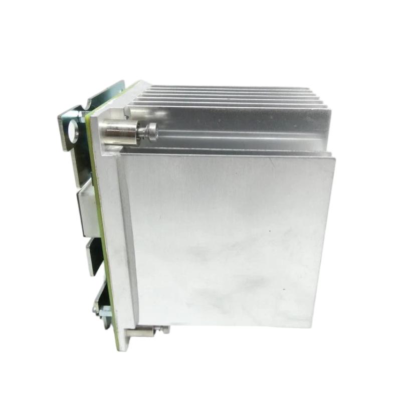
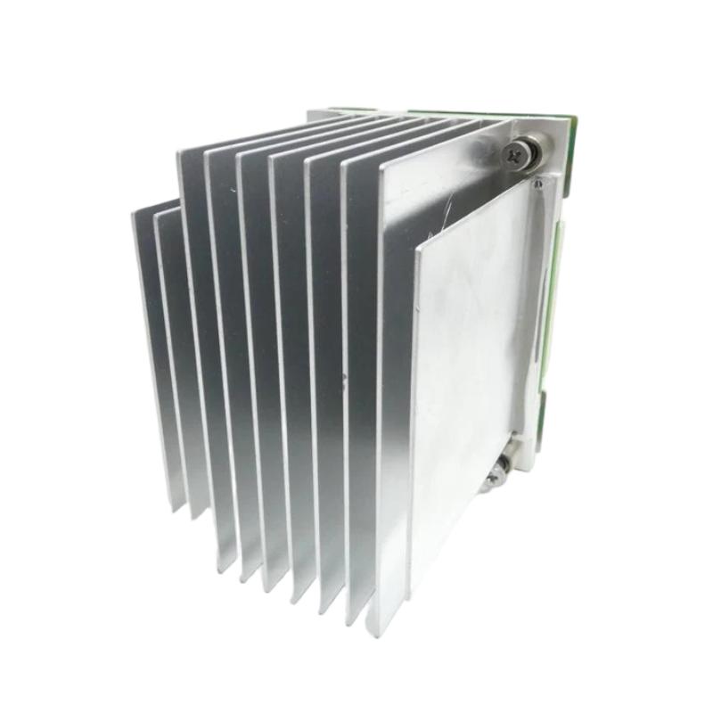
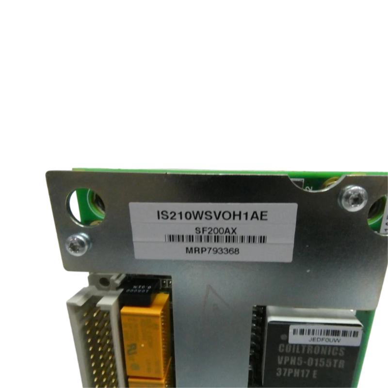
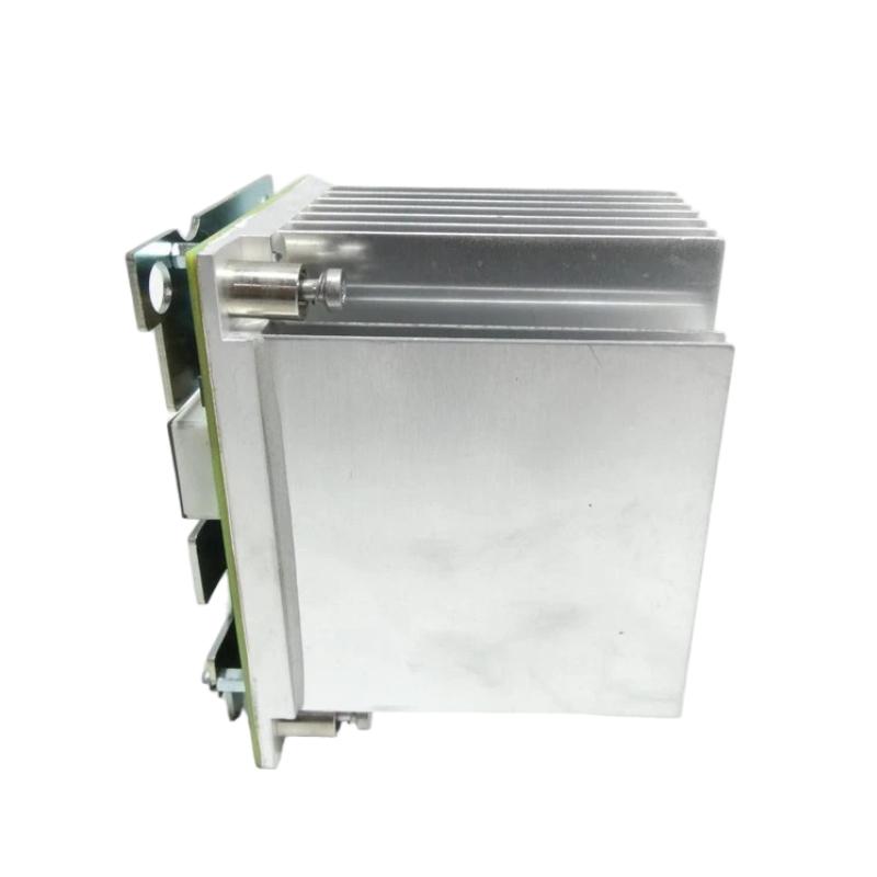
The GE IS210WSVOH1AE Circuit Board Heatsink Assembly is a specialized thermal-management component designed for use with compatible GE industrial control and electronic equipment. The assembly provides a dedicated heat-dissipation structure for circuit-board components that generate heat during normal operation.
In industrial automation systems, electronic assemblies can operate continuously under demanding conditions. Processors, power devices, switching components, interface circuits, and other electronic elements generate heat as electrical energy is converted and processed. Effective thermal management is therefore essential for maintaining stable operating conditions and supporting long-term equipment reliability.
The GE IS210WSVOH1AE has listed dimensions of 280 × 150 × 35 mm and a weight of approximately 0.55 kg. Its relatively thin 35 mm profile makes it suitable for integration into equipment where thermal dissipation must be provided without unnecessarily increasing the overall assembly depth.
The heatsink assembly should be considered part of the complete cooling architecture rather than an independent electronic control module. Its actual mounting arrangement, thermal interface, compatible circuit board, and cooling requirements depend on the host GE equipment.
Technical Specifications
| Parameter | Specification |
|---|---|
| Manufacturer | General Electric (GE) |
| Model | IS210WSVOH1AE |
| Product Type | Circuit Board Heatsink Assembly |
| Product Family | GE IS210 Series |
| Primary Function | Circuit-board thermal management |
| Assembly Type | Heatsink / Cooling Assembly |
| Application | Industrial Control and Electronic Equipment |
| Installation | Compatible GE Industrial Equipment |
| Dimensions | 280 × 150 × 35 mm |
| Weight | 0.55 kg |
| Typical Role | Heat dissipation for associated circuit-board components |
| System Function | Thermal management |
Exact thermal capacity, thermal resistance, mounting hardware, interface material, airflow requirements, and compatible host assemblies should be verified against the applicable system configuration.
What Is the GE IS210WSVOH1AE?
The GE IS210WSVOH1AE is a Circuit Board Heatsink Assembly intended to provide thermal-management support for compatible GE electronic assemblies.
Circuit boards used in industrial control systems often contain components that generate heat during operation. If this heat is not transferred away effectively, component temperatures can increase and potentially affect operating stability and service life.
A heatsink provides a conductive thermal path from the heat-generating component to a larger surface area that can dissipate heat into the surrounding environment.
A simplified thermal path is:
Circuit Board Component → Thermal Interface → IS210WSVOH1AE Heatsink Assembly → Cooling Environment
The effectiveness of this process depends on correct installation, good thermal contact, sufficient airflow, and suitable environmental conditions.
Function and Working Principle
Heat Collection
During operation, electronic components generate heat as a result of electrical losses.
The heatsink assembly receives heat from the associated component through the mechanical and thermal interface between the component and heatsink.
Thermal Conduction
Heat is transferred from the active circuit-board component into the heatsink structure.
Good contact between the component and heatsink is important because unnecessary gaps or contamination can increase thermal resistance.
Heat Dissipation
Once heat reaches the heatsink, the larger exposed surface allows thermal energy to be transferred to the surrounding environment.
Depending on the host equipment, cooling may involve:
- Natural convection
- Forced airflow
- Cabinet ventilation
- Dedicated fans
- Other equipment-level cooling methods
The exact cooling method depends on the system design.
Temperature Stabilization
By helping transfer heat away from the circuit board, the heatsink assembly can support more stable thermal conditions.
This is particularly important for industrial equipment that operates continuously or under variable electrical loading.
Role in Industrial Control Systems
Thermal management is an important supporting function within industrial automation.
Industrial control systems can contain many electronic assemblies operating simultaneously. Even when each individual component produces a moderate amount of heat, the combined thermal load inside a cabinet or equipment enclosure can become significant.
The IS210WSVOH1AE can contribute to the thermal architecture by providing dedicated heat dissipation for compatible circuit-board components.
Its role can be represented as:
Electronic Heat Generation → Thermal Transfer → Heatsink → Airflow / Cooling System → Heat Removal
Maintaining a suitable thermal environment can help support:
- Stable electronic operation
- Reduced thermal stress
- Reliable control-system performance
- Longer component service life
- Consistent equipment operation
Industrial Applications
Industrial Automation Equipment
Industrial automation equipment frequently contains electronic control boards that operate continuously.
A heatsink assembly can help manage the thermal load generated by associated electronic components.
Power and Control Electronics
Power-related electronic components can produce considerable heat during operation.
A dedicated heatsink provides a thermal path for transferring heat away from these components.
Turbine Control Equipment
Industrial turbine control systems may contain electronic assemblies that require reliable thermal management during continuous operation.
The IS210WSVOH1AE can support the cooling architecture of compatible equipment.
Generator and Power-Control Systems
Power-generation equipment often contains multiple control and electronic assemblies.
Maintaining appropriate thermal conditions can help support stable operation of these systems.
Industrial Process Control
Process-control equipment can operate for long periods with relatively constant electrical loading.
Proper heatsink performance helps ensure that associated electronic components remain within appropriate operating conditions.
Thermal Management Architecture
The IS210WSVOH1AE should be installed as part of a complete thermal-management system.
A representative architecture may include:
| Component | Function |
|---|---|
| Circuit Board | Provides electronic control functions |
| Heat-Generating Component | Produces thermal energy |
| Thermal Interface | Transfers heat to heatsink |
| IS210WSVOH1AE | Dissipates heat from associated components |
| Airflow System | Removes heat from heatsink |
| Cabinet Cooling | Controls the surrounding environment |
The exact architecture varies according to the host equipment.
For this reason, a heatsink replacement should always consider the associated circuit board, mounting arrangement, thermal interface, and airflow path.
Installation Guidelines
Confirm the Model
Before installation, verify:
- GE manufacturer identification
- IS210WSVOH1AE model number
- Revision designation
- Existing mounting location
- Associated circuit board
- Mounting hardware
- Thermal interface arrangement
The complete part number should be confirmed before selecting a replacement.
Inspect the Mounting Surface
The mating surfaces between the heatsink and associated components should be clean and free of unnecessary contamination.
A poor contact surface can reduce heat-transfer efficiency.
Check Mechanical Clearance
The listed dimensions of the heatsink assembly are:
280 × 150 × 35 mm
Cabinet and equipment layouts should also account for:
- Mounting hardware
- Cable clearance
- Airflow
- Adjacent components
- Maintenance access
The nominal dimensions do not necessarily represent the complete installation envelope.
Maintain Airflow
If the host equipment uses forced airflow, the heatsink should be positioned correctly relative to the cooling path.
Cables and adjacent components should not unnecessarily obstruct airflow around the heat-dissipation surfaces.
Thermal Interface Considerations
The thermal interface between the circuit-board component and heatsink is a critical part of the cooling system.
Potential causes of poor thermal transfer include:
- Contaminated contact surfaces
- Improper mounting
- Uneven mechanical contact
- Damaged thermal-interface material
- Incorrect assembly
- Excessive mechanical stress
During maintenance, technicians should inspect both the heatsink and the associated component interface.
A heatsink that appears physically intact can still provide poor thermal performance if the thermal interface is improperly installed.
Commissioning and Inspection
After installation, the heatsink assembly should be inspected as part of the complete equipment commissioning process.
Step 1: Visual Inspection
Check for:
- Physical damage
- Deformation
- Corrosion
- Contamination
- Damaged mounting points
Step 2: Mechanical Verification
Confirm that the heatsink is securely mounted and correctly aligned with the associated circuit-board assembly.
Step 3: Thermal Interface Check
Where applicable, verify that the thermal interface is properly installed and provides suitable contact.
Step 4: Airflow Inspection
Check that cooling paths are not obstructed by:
- Cables
- Dust
- Cabinet components
- Other mechanical structures
Step 5: Temperature Monitoring
During controlled operation, monitor relevant equipment temperature indicators or diagnostic information.
An abnormal temperature trend can indicate problems elsewhere in the thermal-management system.
Troubleshooting the GE IS210WSVOH1AE
Excessive Circuit Board Temperature
If the associated circuit board operates at an unexpectedly high temperature, inspect:
- Heatsink condition
- Thermal interface
- Mounting
- Airflow
- Cooling fans
- Cabinet ventilation
- Ambient temperature
- Electrical loading
The heatsink should not automatically be considered the source of the problem.
Reduced Heat Dissipation
Poor cooling performance can result from:
- Dust accumulation
- Restricted airflow
- Poor thermal contact
- Loose mounting
- Damaged thermal-interface material
- Increased component loading
- High ambient temperature
A complete thermal inspection is recommended before replacing the heatsink.
Physical Damage
Inspect the heatsink for:
- Bent surfaces
- Cracks
- Deformation
- Damaged mounting points
- Corrosion
- Blocked cooling surfaces
Mechanical damage can affect both mounting integrity and heat dissipation.
Temperature Gradually Increasing
A gradual temperature increase may indicate:
- Accumulated contamination
- Reduced airflow
- Cooling fan deterioration
- Thermal-interface degradation
- Increased system loading
- Higher ambient temperature
Temperature trend monitoring can help identify these problems before they result in equipment shutdown.
Preventive Maintenance
Keep the Heatsink Clean
Dust and contamination can reduce exposed cooling surface area and restrict airflow.
Cleaning should follow the maintenance procedures appropriate for the host equipment.
Inspect Mounting Hardware
Loose mounting can reduce thermal contact and may also create mechanical vibration.
Check Thermal Interface
During scheduled maintenance, inspect the interface between the heatsink and associated heat-generating components.
Monitor Equipment Temperature
Temperature monitoring provides useful information about the overall cooling performance of the electronic assembly.
Maintain Cabinet Ventilation
The surrounding cabinet should provide suitable airflow and should not contain unnecessary obstructions around cooling components.
Replacement Considerations
When replacing the GE IS210WSVOH1AE Circuit Board Heatsink Assembly, technicians should verify the exact model and associated hardware.
Important replacement checks include:
- Complete model number
- Revision designation
- Associated circuit board
- Mounting arrangement
- Thermal interface
- Mounting hardware
- Airflow direction
- Available cabinet clearance
The listed physical characteristics are:
- Dimensions: 280 × 150 × 35 mm
- Weight: 0.55 kg
- Product Type: Circuit Board Heatsink Assembly
Physical dimensions should be verified before replacement because mounting interfaces and surrounding clearances can affect compatibility.
A visually similar heatsink should not automatically be considered interchangeable.
Physical Dimensions and Weight
The GE IS210WSVOH1AE has listed dimensions of 280 × 150 × 35 mm and a listed weight of 0.55 kg.
These specifications are useful for:
- Cabinet planning
- Spare-parts inventory
- Replacement preparation
- Equipment transportation
- Mechanical clearance planning
- Maintenance scheduling
The 35 mm listed depth is particularly relevant when assessing the available space around the associated circuit board and other cabinet components.
Compatible System Components
The IS210WSVOH1AE may be incorporated into a larger GE industrial equipment assembly containing:
- GE circuit boards
- Control processors
- Power electronic devices
- Interface boards
- Terminal assemblies
- Cooling fans
- Cabinet ventilation equipment
- Thermal interface materials
- Mounting hardware
- Industrial control equipment
The exact compatible components depend on the host system and mechanical configuration.
The IS210 family designation alone should not be used to determine direct interchangeability.
Engineering Best Practices
Maintain Good Thermal Contact
The interface between the heatsink and heat-generating component should be installed correctly to minimize unnecessary thermal resistance.
Keep Cooling Paths Clear
Avoid routing cables or installing hardware in a way that blocks intended airflow.
Monitor Temperature Trends
A gradual increase in operating temperature can provide an early indication of a developing cooling problem.
Inspect the Complete Thermal System
If an electronic assembly becomes excessively hot, inspect the heatsink, thermal interface, airflow, cooling fans, cabinet environment, and component loading.
Record Exact Spare-Part Identification
The complete IS210WSVOH1AE model number should be recorded in the maintenance system to reduce the risk of selecting an incorrect replacement.
Key Advantages
Dedicated Circuit-Board Cooling
The IS210WSVOH1AE provides a dedicated heatsink structure for thermal management of compatible circuit-board components.
Compact Profile
With listed dimensions of 280 × 150 × 35 mm, the assembly provides a relatively compact thermal-management solution for industrial equipment.
Supports Thermal Stability
By transferring heat away from associated electronic components, the heatsink assembly can contribute to maintaining stable operating temperatures.
Industrial Application
The assembly is designed for integration into industrial electronic and control equipment where continuous thermal management is important.
Maintainable Construction
A dedicated heatsink assembly can be inspected, cleaned, and replaced as part of scheduled industrial maintenance.
Technical FAQs
What is the GE IS210WSVOH1AE?
The GE IS210WSVOH1AE is a Circuit Board Heatsink Assembly designed to support thermal management for compatible GE industrial electronic equipment.
What is the main function of the IS210WSVOH1AE?
Its primary function is to transfer heat away from associated circuit-board components and dissipate that heat into the surrounding cooling environment.
What are the dimensions of the IS210WSVOH1AE?
The listed dimensions are 280 × 150 × 35 mm.
How much does the IS210WSVOH1AE weigh?
The listed weight is approximately 0.55 kg.
Is the IS210WSVOH1AE an electronic control board?
No. It is a heatsink assembly used for thermal management rather than a processor, PLC, or conventional I/O board.
What can cause poor heatsink performance?
Possible causes include contamination, restricted airflow, poor thermal contact, damaged thermal-interface material, loose mounting, increased equipment loading, or high ambient temperature.
How should the heatsink assembly be maintained?
Maintenance should include inspection for contamination, physical damage, loose mounting, airflow obstruction, and deterioration of the thermal interface.
Can another GE heatsink replace the IS210WSVOH1AE?
It should not be assumed that another GE heatsink is interchangeable. The complete model number, mechanical interface, associated circuit board, and thermal requirements should be verified.
Why is the thermal interface important?
The thermal interface provides the heat-transfer path between the circuit-board component and heatsink. Poor contact can increase thermal resistance and reduce cooling effectiveness.
What should be checked before replacement?
Verify the complete model number, dimensions, mounting arrangement, associated circuit board, thermal interface, available clearance, and airflow requirements before installation.
Conclusion
The GE IS210WSVOH1AE Circuit Board Heatsink Assembly is a specialized thermal-management component designed to support heat dissipation from compatible GE industrial electronic and control equipment. By providing a dedicated thermal path between heat-generating circuit-board components and the surrounding cooling environment, the assembly can contribute to stable operation and long-term equipment reliability.
With listed dimensions of 280 × 150 × 35 mm and a weight of 0.55 kg, the IS210WSVOH1AE provides a compact heatsink solution suitable for appropriately designed industrial equipment.
For reliable performance, the heatsink should be correctly mounted with suitable thermal contact and sufficient airflow. During maintenance, technicians should evaluate the complete cooling system—including the heatsink, thermal interface, airflow, cabinet environment, and associated electronic components—rather than treating the heatsink as an isolated component.
When sourcing a replacement, the complete GE IS210WSVOH1AE identification should be verified together with the associated circuit-board assembly, mechanical mounting arrangement, and thermal requirements.