

ProductPRODUCT
Featured products
Contact Us
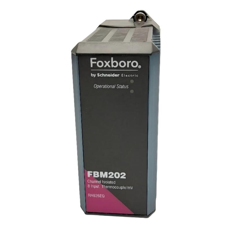
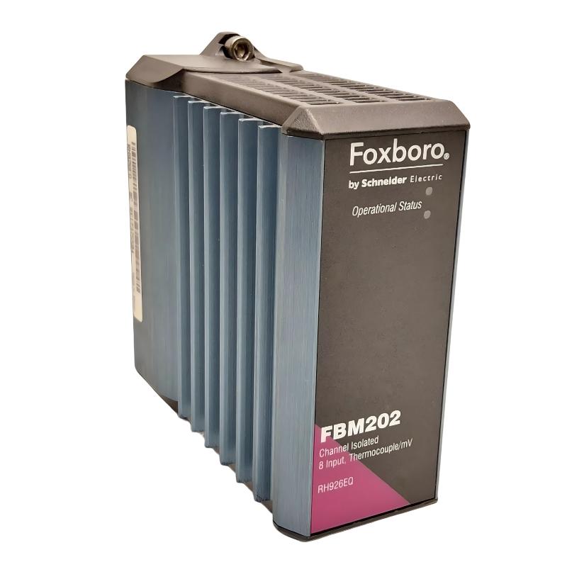
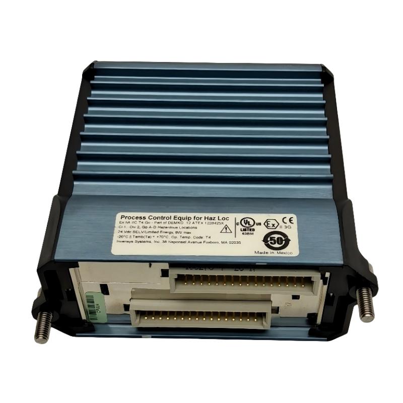
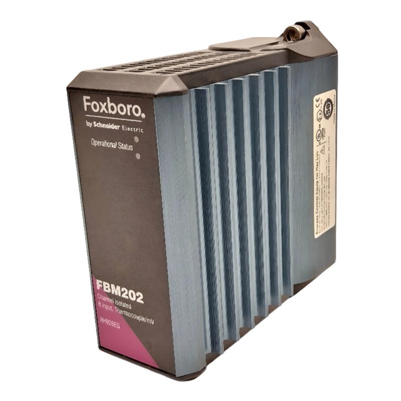
- Foxboro
- FBM202 RH926EQ
- Thermocouple/mV Input Module
- USA
- 114 × 45 × 104 mm
- 0.284 kg
- Xiamen, China
- New & In Stock
- T/T, PayPal, Western Union
- 1 Year
- 1-3 Working Days
- DHL, UPS, TNT, FedEx and EMS.
- 24-Hour Service
- COO
- 22
Our advantage

Global Logistics
We have a 10-year logistics and express cooperation agreement, so our products can be shipped to any place in the world.

Brand new and original
Our products are imported in bulk from the place of origin. Because of the cooperative relationship, our products are all original and 100% new.

24-hour service
We provide 7*24 hours service to our customers. We will be there whenever you need us.

Price advantage
All our products are priced very favorably because we have our own warehouse and supply.
| Company Information | |||
| [email protected] | |||
| Mobile | +8615980777398 | ||
| +8615980777398 | |||
| 15980777398 |
Product Overview
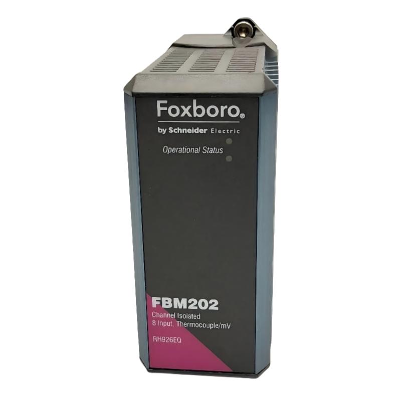
The Foxboro FBM202 RH926EQ is an I/A Series 200 Thermocouple/mV Input Module used for acquiring low-level temperature and millivolt signals in Foxboro process control systems. It connects thermocouple-based field measurements to the I/A Series control architecture, allowing process temperatures and other millivolt signals to be monitored and used by the control strategy.
In a typical cabinet, the signal path runs from the thermocouple or millivolt source through the field wiring and termination hardware to the FBM202. The module handles the input interface before the measurement is passed into the control system for display, alarming, trending, or process control.
Thermocouple applications require attention to the complete measurement path. Sensor type, polarity, extension or compensating cable, terminal connections, and cabinet wiring can all affect the final value seen by the control system. For this reason, troubleshooting the FBM202 is normally carried out together with the associated field circuit.
Technical Specifications
| Parameter | Specification |
|---|---|
| Model | FBM202 RH926EQ |
| Series | I/A Series 200 |
| Product Type | Thermocouple/mV Input Module |
| Dimensions | 114 × 45 × 104 mm |
| Weight | 0.284 kg |
| Input Application | Thermocouple and millivolt signal acquisition |
| System Application | Foxboro I/A Series process measurement |
Product Features
- Thermocouple and millivolt input capability for I/A Series 200 systems.
- Handles low-level signals used for process temperature measurement.
- Interfaces field temperature signals with the Foxboro control architecture.
- Suitable for continuous process monitoring and temperature-related control functions.
- Works with field termination hardware and associated I/A Series components.
- Supports maintenance and replacement of compatible I/A Series 200 installations.
Working Principle
The FBM202 receives the electrical signal generated by a thermocouple or other millivolt-level source. The module conditions and acquires the low-level input so that the measurement can be transferred to the I/A Series control system.
For thermocouple measurement, the module is only one part of the complete measurement chain. The thermocouple produces a small voltage according to the temperature difference between its sensing junction and reference point. That signal travels through the appropriate wiring and termination path before reaching the FBM202.
In field troubleshooting, technicians can therefore work through the signal path step by step. If the field measurement is correct but the control-system value is incorrect, the investigation can move toward the wiring, termination assembly, module connection, and system configuration. This approach helps avoid unnecessary replacement of otherwise functional I/O hardware.
Role in the I/A Series 200 Control Architecture
| System Element | Function |
|---|---|
| Thermocouple / mV Source | Generates the low-level process measurement signal. |
| Field Wiring | Carries the measurement signal from the process area to the control cabinet. |
| Termination Assembly | Provides the physical connection between field wiring and I/O hardware. |
| FBM202 RH926EQ | Acquires thermocouple and millivolt input signals. |
| I/A Series Control Network | Transfers acquired measurement data within the control system. |
| Control Processor | Uses process measurements for control logic, monitoring, and alarms. |
| Operator Interface | Presents temperature values, trends, alarms, and diagnostic information. |
Industrial Applications
| Application | Typical Use |
|---|---|
| Process Temperature Measurement | Acquisition of thermocouple signals from industrial process equipment. |
| Chemical Processing | Temperature monitoring for reactors, vessels, heaters, and process lines. |
| Oil and Gas | Temperature acquisition from production and processing equipment. |
| Refining and Petrochemical | Monitoring temperatures in furnaces, heaters, vessels, and process units. |
| Power Generation | Temperature monitoring of boilers, turbines, auxiliary systems, and process equipment. |
| Industrial Heating | Monitoring temperature in controlled heating and thermal processing equipment. |
Installation and Maintenance
- Verify the exact module identification before installation. Confirm FBM202 RH926EQ and the applicable I/A Series 200 configuration.
- Isolate the relevant circuits before removing or installing the module and follow the site’s electrical safety procedures.
- Confirm the thermocouple type before connecting the field circuit. The sensor and system configuration must correspond to the intended measurement.
- Check thermocouple polarity during installation. Incorrect polarity can result in an incorrect temperature indication.
- Inspect field wiring and terminals for loose conductors, damaged insulation, corrosion, or poor connections.
- Use appropriate thermocouple or compensating cable throughout the measurement path. Incorrect cable types can introduce measurement errors.
- Inspect the termination assembly if the field sensor appears to be operating correctly but the control-system reading is abnormal.
- Check for electrical interference when the measured value fluctuates unexpectedly. Signal routing, shielding, and grounding should be reviewed according to site practices.
- Compare the field signal with the system value during troubleshooting to determine whether the problem is located at the sensor, wiring, termination, or FBM.
- Keep the cabinet environment clean and dry to reduce the possibility of contamination or connection problems affecting low-level signals.
- Perform loop and functional checks after replacement to verify the correct channel and expected measurement response.
- Document the final wiring and configuration after maintenance so future troubleshooting can follow the actual installed signal path.
Compatible System Components
| Component | Function |
|---|---|
| Foxboro I/A Series 200 Termination Assemblies | Provide field-side connections for thermocouple and mV wiring. |
| Thermocouples | Generate temperature-dependent millivolt signals. |
| Millivolt Signal Sources | Provide low-level analog measurement inputs. |
| Thermocouple Extension / Compensating Cable | Carries thermocouple signals between the sensor and termination point. |
| I/A Series 200 Control Processors | Use acquired measurements for control and monitoring. |
| I/A Series Operator Interfaces | Display process values, trends, alarms, and status information. |
| I/A Series Communication Components | Transfer I/O information within the control architecture. |
Recommended Related Models
| Model / Product Family | Product Type | Typical Application |
|---|---|---|
| Foxboro FBM202 | I/A Series 200 Thermocouple/mV Input Module | Thermocouple and mV signal acquisition |
| Foxboro I/A Series 200 FBM Family | Fieldbus Modules | Process I/O signal acquisition |
| Foxboro I/A Series 200 Termination Assemblies | Termination Hardware | Field-to-I/O connections |
| Foxboro I/A Series Analog Input Modules | Analog Input Hardware | Process measurement acquisition |
| Foxboro I/A Series Temperature Input Components | Temperature I/O Hardware | Thermocouple-based process monitoring |
Key Advantages
- Supports thermocouple and millivolt process measurements.
- Handles low-level temperature measurement signals within the I/A Series 200 architecture.
- Connects field temperature instrumentation with the Foxboro control system.
- Suitable for continuous monitoring and temperature-based control applications.
- Supports practical signal-path troubleshooting from the sensor through the I/O module.
Technical FAQs
What is the Foxboro FBM202 RH926EQ used for?
The FBM202 RH926EQ is an I/A Series 200 Thermocouple/mV Input Module used to acquire thermocouple and millivolt-level signals for Foxboro process control applications.
What can cause an incorrect temperature value at the FBM202?
Incorrect thermocouple polarity, unsuitable extension or compensating cable, loose terminals, damaged field wiring, electrical interference, or a problem with the sensor can all affect the measured value. The complete signal path should be checked before replacing the module.
How should an FBM202 input problem be troubleshot?
Compare the expected field measurement with the value received by the control system. Then inspect the thermocouple, wiring, termination assembly, module connections, and system configuration in sequence.
What should be verified before replacing an FBM202 RH926EQ?
Verify the exact model and system configuration, confirm the thermocouple type and wiring, document existing connections, and check the field signal path. After installation, perform the appropriate loop and functional checks to confirm correct channel operation.