

ProductPRODUCT
Featured products
Contact Us
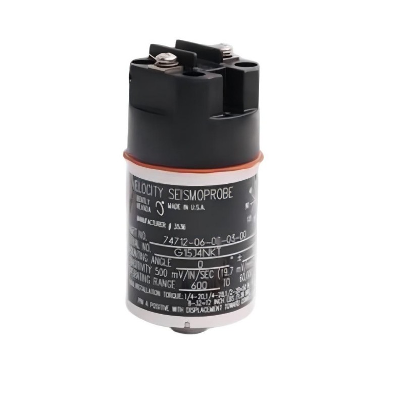
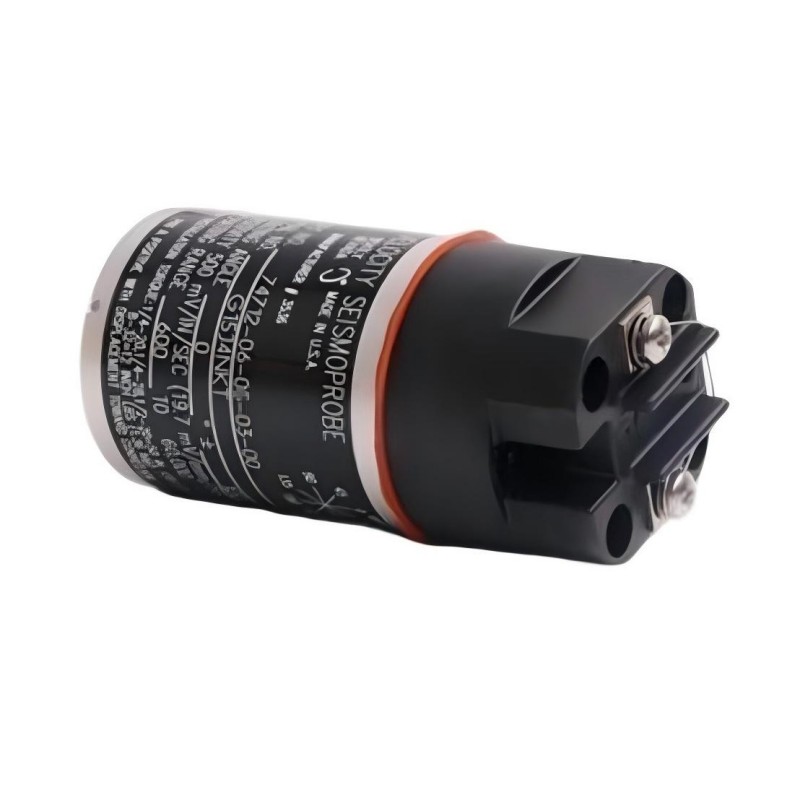
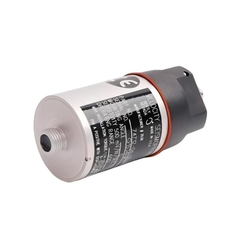
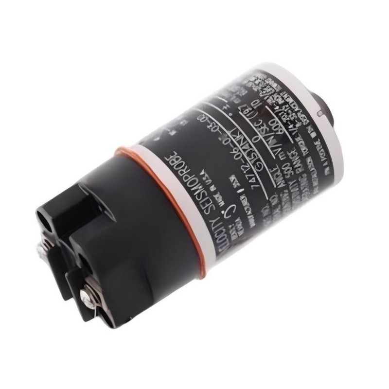
- Bently Nevada
- 74712-06-03-03-00
- High Temperature Two-Wire Velocity Transducer
- USA
- 41 mm
- 0.48 kg
- Xiamen, China
- New & In Stock
- T/T, PayPal, Western Union
- 1 Year
- 1-3 Working Days
- DHL, UPS, TNT, FedEx and EMS.
- 24-Hour Service
- COO
- 19
Our advantage

Global Logistics
We have a 10-year logistics and express cooperation agreement, so our products can be shipped to any place in the world.

Brand new and original
Our products are imported in bulk from the place of origin. Because of the cooperative relationship, our products are all original and 100% new.

24-hour service
We provide 7*24 hours service to our customers. We will be there whenever you need us.

Price advantage
All our products are priced very favorably because we have our own warehouse and supply.
| Company Information | |||
| [email protected] | |||
| Mobile | +8615980777398 | ||
| +8615980777398 | |||
| 15980777398 |
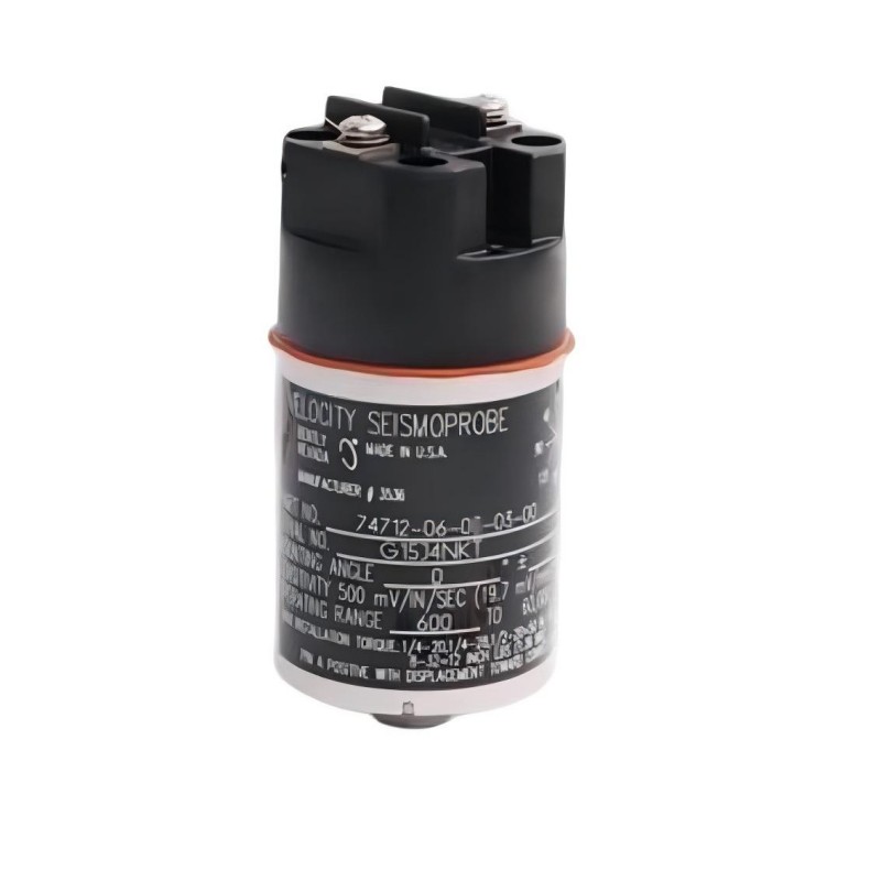
Product Overview
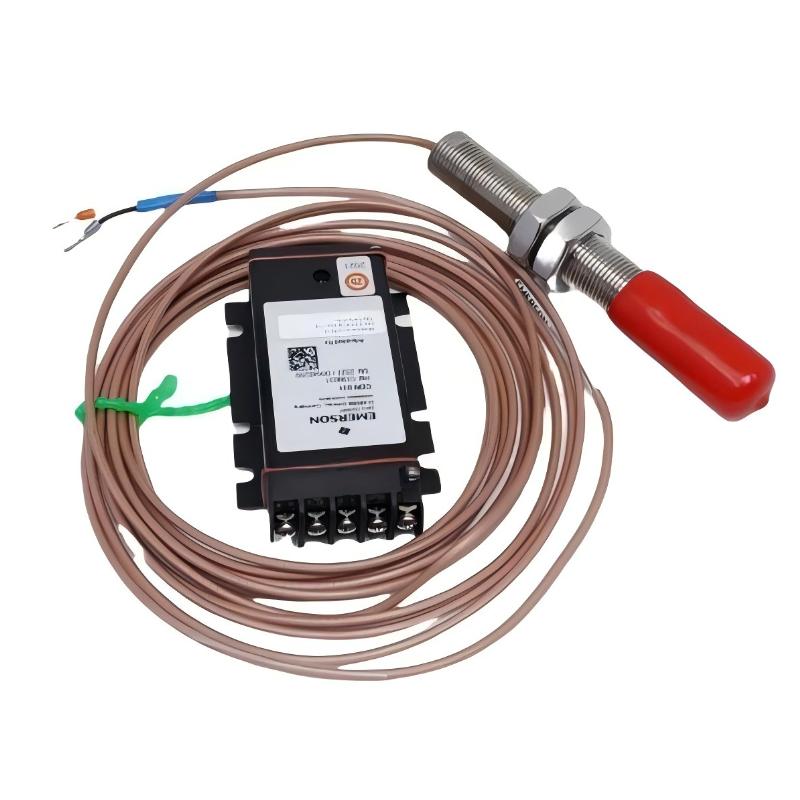
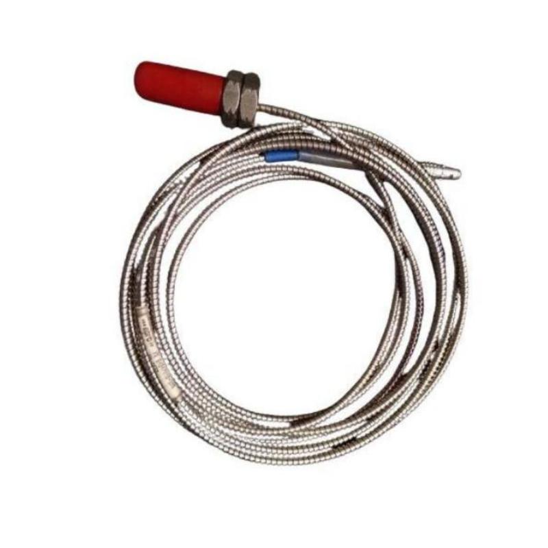
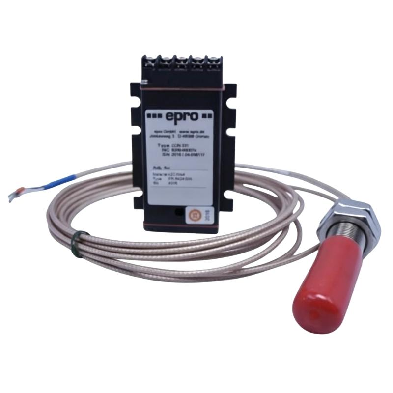
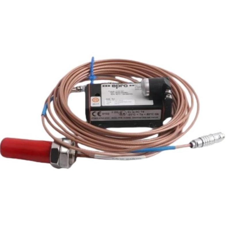
The Bently Nevada 74712-06-03-03-00 High Temperature Two-Wire Velocity Transducer is a machine-mounted vibration sensor for rotating equipment operating in environments where elevated temperature is a consideration. Its velocity-based output can be routed through a two-wire field circuit to compatible vibration monitoring equipment.
In a typical installation, the transducer is mounted directly to the housing of a motor, pump, compressor, fan, or other rotating machine. Mechanical vibration reaches the sensing element through the mounting interface, and the resulting electrical signal is sent to the monitoring channel for display, trending, alarm processing, or machinery protection.
For maintenance engineers, the complete measurement path matters as much as the sensor itself. Mounting condition, field wiring, monitoring-channel compatibility, and actual machine vibration should be checked together when commissioning or troubleshooting a 74712-06-03-03-00 installation.
Technical Specifications
| Parameter | Specification |
|---|---|
| Product | Bently Nevada 74712-06-03-03-00 |
| Product Type | High Temperature Two-Wire Velocity Transducer |
| Series | 74712 Series |
| Measurement | Vibration Velocity |
| Signal Configuration | Two-Wire |
| Sensor Type | Machine-Mounted Velocity Transducer |
| Application | Rotating Machinery Vibration Monitoring |
| Installation | Direct Machine Mounting |
| Diameter | 41 mm |
| Weight | 0.48 kg |
Product Features
- High-temperature vibration sensing for machinery locations exposed to elevated operating temperatures.
- Two-wire signal transmission for connection to a compatible monitoring input.
- Velocity measurement for applications where vibration velocity is the required monitoring parameter.
- Direct machine mounting transfers casing vibration into the sensing element.
- Suitable for continuous rotating-equipment monitoring.
- Can form part of a broader machinery monitoring and protection channel.
Working Principle
The transducer is mounted to the monitored machine at a location that represents the vibration of the rotating assembly. When the machine operates, casing movement is transferred through the mounting interface to the internal velocity-sensing mechanism.
The sensor converts this mechanical vibration into an electrical signal associated with vibration velocity. The signal travels through the two-wire circuit to the compatible monitoring input, where it can be conditioned, displayed, trended, or used for alarm and protection functions.
If the measured signal is unexpectedly low, unstable, or absent, the sensor should not be isolated from the rest of the circuit during diagnosis. A loose mounting point, damaged cable, poor termination, unsuitable input channel, or genuine change in machine vibration can produce similar symptoms.
Role in Machinery Vibration Monitoring Control Architecture
| System Element | Function |
|---|---|
| 74712-06-03-03-00 Transducer | Converts machine vibration into a velocity-related electrical signal |
| Machine Housing | Transfers mechanical vibration to the transducer |
| Two-Wire Field Circuit | Carries the sensor signal to the monitoring equipment |
| Monitoring Input | Receives and processes the transducer signal |
| Signal Conditioning | Prepares the signal for monitoring and protection functions |
| Machinery Protection System | Uses vibration information for alarm and protective functions |
| Plant Monitoring System | Provides operators and maintenance personnel with vibration information |
| Rotating Equipment | Generates the vibration being measured |
Industrial Applications
| Application | Typical Use |
|---|---|
| High-Temperature Machinery | Monitoring vibration where the sensor installation point experiences elevated temperature |
| Motors | Observing casing vibration during continuous motor operation |
| Pumps | Tracking changes in vibration associated with rotating equipment condition |
| Compressors | Monitoring vibration on process and rotating compressor machinery |
| Fans and Blowers | Detecting changes in operating vibration |
| Process Equipment | Adding vibration measurement to industrial rotating machinery |
| Machinery Protection | Feeding velocity information into compatible protection channels |
| Condition Monitoring | Supporting vibration trending and maintenance inspection |
Installation and Maintenance
- Confirm the installation environment: Check the expected operating temperature and machine vibration conditions at the proposed sensor location.
- Choose a representative mounting point: Select a rigid machine surface that provides a useful vibration path from the rotating equipment.
- Prepare the mounting surface: Remove dirt, loose material, excessive coating, or other contamination that could compromise mechanical contact.
- Secure the transducer correctly: Check that the sensor is firmly mounted and free from unwanted mechanical movement.
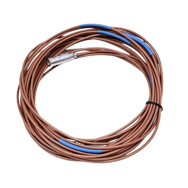
- Route the field cable carefully: Keep the two-wire circuit away from excessive heat, moving components, sharp edges, and other potential sources of damage.
- Inspect electrical connections: Verify cable continuity and field terminations before placing the monitoring channel into service.
- Check input compatibility: Confirm that the receiving vibration channel supports the required two-wire sensor configuration.
- Verify the commissioning signal: Observe the initial signal with the machine operating under a known condition and compare it with expected behavior.
- Establish a vibration trend: Record operating data so that future changes can be distinguished from normal machine behavior.
- Troubleshoot the complete signal path: If the signal is abnormal, inspect mounting, wiring, monitoring input, and machine condition before replacing the sensor.
- Inspect during scheduled shutdowns: Examine the sensor mounting point, cable routing, terminals, and surrounding temperature exposure.
- Match the replacement configuration: Verify the complete 74712 model designation and monitoring-channel requirements before installing a replacement unit.
Compatible System Components
| Component | Function |
|---|---|
| Two-Wire Vibration Monitoring Input | Receives the velocity transducer signal |
| Signal Conditioning Equipment | Conditions the sensor signal for downstream processing |
| Machinery Protection System | Processes vibration information for alarm and protection |
| Vibration Monitoring System | Displays and trends machine vibration |
| Industrial Field Cable | Connects the transducer with the monitoring input |
| Machine Mounting Hardware | Maintains the mechanical interface between sensor and equipment |
| Rotating Machinery | Provides the vibration source being monitored |
| Plant Monitoring Interface | Makes vibration information available to operators and maintenance personnel |
Recommended Related Models
| Model / Product Family | Product Type | Typical Application |
|---|---|---|
| Bently Nevada 74712 Series | High Temperature Velocity Transducers | Vibration monitoring at elevated-temperature machine locations |
| Bently Nevada High Temperature Vibration Transducers | Industrial Vibration Transducers | Machinery monitoring in high-temperature environments |
| Bently Nevada Two-Wire Velocity Transducers | Velocity Transducers | Two-wire vibration velocity measurement |
| Bently Nevada Machinery Protection Systems | Machinery Protection Systems | Vibration alarm and equipment protection |
| Bently Nevada Vibration Monitoring Components | Monitoring Components | Building complete rotating-equipment monitoring channels |
Key Advantages
- High-temperature vibration monitoring
- Two-wire signal configuration
- Vibration velocity measurement
- Direct machine-mounted installation
- Suitable for rotating machinery monitoring
- Integration with compatible monitoring channels
Technical FAQs
What does the 74712-06-03-03-00 measure?
It measures vibration velocity and sends the resulting signal through a two-wire connection to compatible monitoring equipment.
Where is this type of transducer typically mounted?
It is normally installed directly on the housing of rotating equipment at a location where the machine’s casing vibration can be transferred effectively to the sensor.
What can cause an unexpectedly weak or missing vibration signal?
Possible causes include loose mounting, damaged field wiring, poor electrical termination, an incompatible monitoring input, or an actual change in machine operating condition. The complete measurement chain should be checked.
Is a two-wire input automatically compatible with the 74712-06-03-03-00?
No. The receiving channel must match the electrical and signal requirements of the transducer. The sensor and monitoring input should be treated as a matched measurement chain during system configuration.