
NewsNEWCENTER
Featured products
Contact Us
Allen Bradley 1606-XLE480EP Power Supply Installation Guide
2026-09-10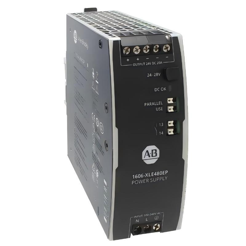 Table of Contents
- Allen Bradley 1606-XLE480EP Power Supply Installation Overview
- Allen Bradley 1606-XLE480EP Installation Planning and Power Distribution
- Allen Bradley 1606-XLE480EP Installation Environment Requirements
- Allen Bradley 1606-XLE480EP Wiring and Electrical Installation
- Allen Bradley 1606-XLE480EP Setup and Commissioning Procedure
- Allen Bradley 1606-XLE480EP System Configuration Verification
- Allen Bradley 1606-XLE480EP Real Commissioning Case
- Allen Bradley 1606-XLE480EP Installation FAQ
- Allen Bradley 1606-XLE480EP Technical Summary
Allen Bradley 1606-XLE480EP Power Supply Installation Overview
Allen Bradley 1606-XLE480EP Power Supply installation is the foundation of a stable industrial control system. Most startup failures are not caused by the power supply itself but by incorrect cable sizing, poor grounding, overloaded DC branches or improper cabinet layout. A professional Installation Guide should therefore verify the complete power distribution network before energizing the system.
The Allen Bradley 1606-XLE480EP Power Supply provides regulated DC power for PLC Controllers, industrial PCs, Ethernet switches, distributed I/O Modules, Sensors, HMIs and motion control equipment. Correct Setup and Commissioning improve equipment availability and reduce long-term maintenance costs.
Allen Bradley 1606-XLE480EP Installation Planning and Power Distribution
Before mounting the unit, engineers should evaluate the complete System Configuration instead of focusing only on the power supply.
- Calculate the maximum DC load.
- Reserve at least 20% expansion capacity.
- Separate logic power from inductive loads.
- Review branch fuse coordination.
- Confirm protective earth continuity.
- Verify cabinet cooling capability.
- Plan cable routing to minimize EMI.
A properly designed power distribution system significantly improves PLC stability and communication reliability.
Allen Bradley 1606-XLE480EP Installation Environment Requirements
The power supply should be installed inside a clean industrial control cabinet with adequate airflow. High-temperature devices such as variable frequency drives, braking resistors and transformers should be positioned away from the power supply whenever possible.
Control wiring should be routed separately from high-current motor cables to minimize electrical interference affecting communication networks and Sensors.
Allen Bradley 1606-XLE480EP Wiring and Electrical Installation
Complete all electrical work only after isolating the incoming AC supply.
- Verify incoming AC voltage.
- Connect protective earth first.
- Confirm input wiring polarity.
- Connect regulated DC output.
- Inspect terminal torque.
- Label all outgoing circuits.
- Verify insulation resistance before startup.
Incoming AC
      │
      ▼
1606-XLE480EP
      │
      ▼
24VDC Distribution
      │
 ├── PLC Controller
 ├── Remote I/O Modules
 ├── Industrial Ethernet
 ├── HMI
 ├── Servo Controller
 └── Field Sensors
Measure continuity before energizing downstream equipment.
Allen Bradley 1606-XLE480EP Setup and Commissioning Procedure
Successful Commissioning introduces electrical loads gradually rather than powering every device simultaneously.
- Measure incoming AC voltage.
- Verify unloaded DC output.
- Power the PLC Controller.
- Start communication devices.
- Connect remote I/O Modules.
- Enable field Sensors.
- Run production equipment under full operating load.
Record all electrical measurements during Setup and Commissioning. These values provide the baseline for future Troubleshooting and Fault Diagnosis.
Allen Bradley 1606-XLE480EP System Configuration Verification
- Stable 24VDC output.
- No PLC restart events.
- Reliable Ethernet communication.
- Normal Sensor signals.
- Minimal voltage drop.
- No abnormal cabinet heating.
- Stable operation during continuous production.
Always compare voltage measured directly at the power supply with measurements taken at the furthest field device. Excessive voltage loss generally indicates wiring or distribution issues.
Allen Bradley 1606-XLE480EP Real Commissioning Case
During commissioning of an automated logistics system, engineers observed random communication interruptions whenever multiple servo drives accelerated simultaneously.
The Allen Bradley 1606-XLE480EP Power Supply was initially suspected because every remote controller shared the same 24 VDC supply.
Measurements showed the power supply output remained stable at approximately 24.15 VDC, while the voltage inside the remote control cabinet dropped to approximately 21.9 VDC during peak current demand.
Further investigation found an undersized feeder cable and an improperly tightened distribution terminal. After replacing the cable and tightening the terminal block, the remote voltage increased to approximately 24.0 VDC and communication remained stable throughout continuous production.
This field experience demonstrates that engineers should verify the entire DC distribution network before replacing a power supply.
Allen Bradley 1606-XLE480EP Installation FAQ
Why should the unloaded output voltage be measured first?
This confirms that the power supply is operating correctly before additional equipment affects system performance.
Should remote cabinet voltage also be measured?
Yes. Voltage drop often occurs within distribution wiring instead of at the power supply terminals.
Why is proper grounding important?
Correct grounding improves EMC performance, communication stability and equipment reliability.
Why record commissioning measurements?
Baseline electrical values make future Fault Diagnosis significantly faster and more accurate.
Allen Bradley 1606-XLE480EP Technical Summary
The Allen Bradley 1606-XLE480EP Power Supply Installation Guide should emphasize engineering planning, structured Setup, staged Commissioning and complete System Configuration verification. Proper installation practices ensure stable operation of PLC Controllers, I/O Modules, Sensors and industrial communication equipment while minimizing unplanned downtime.