
NewsNEWCENTER
Featured products
Contact Us
Allen Bradley 1336-PB-SP5A Precharge Circuit Board Installation Guide
2026-09-07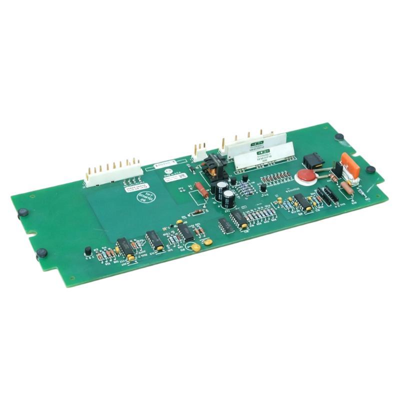
Table of Contents
- Allen Bradley 1336-PB-SP5A Precharge Circuit Board Installation Overview
- Allen Bradley 1336-PB-SP5A Precharge Circuit Board Function
- Allen Bradley 1336-PB-SP5A Pre-Installation Inspection
- Allen Bradley 1336-PB-SP5A Board Replacement Procedure
- Allen Bradley 1336-PB-SP5A System Configuration Verification
- Allen Bradley 1336-PB-SP5A Setup and Commissioning
- Allen Bradley 1336-PB-SP5A Real Engineering Case
- Allen Bradley 1336-PB-SP5A Installation FAQ
- Allen Bradley 1336-PB-SP5A Technical Summary
Allen Bradley 1336-PB-SP5A Precharge Circuit Board Installation Overview
Allen Bradley 1336-PB-SP5A Precharge Circuit Board installation is critical for ensuring a controlled charging process of the drive DC bus during power-up. Improper installation may lead to excessive inrush current, nuisance drive faults or premature damage to capacitors and switching components. A professional Installation Guide focuses on electrical safety, correct board positioning and verification of the complete drive system before commissioning.
The 1336-PB-SP5A Precharge Circuit Board operates as part of the Allen Bradley 1336 drive architecture and should always be installed together with a complete inspection of associated wiring, connectors and protective components.
Allen Bradley 1336-PB-SP5A Precharge Circuit Board Function
The precharge circuit gradually energizes the DC bus capacitors when AC input power is applied. Instead of allowing instantaneous charging current, the circuit limits inrush current until the DC bus reaches a safe operating level.
- Limits capacitor charging current.
- Protects rectifier components.
- Reduces electrical stress during startup.
- Supports stable drive initialization.
- Improves long-term drive reliability.
A correctly operating precharge circuit contributes directly to reliable Setup, Commissioning and continuous production.
Allen Bradley 1336-PB-SP5A Pre-Installation Inspection
Before replacing the board, isolate the drive according to plant lockout procedures and allow sufficient time for the DC bus to discharge completely.
- Disconnect incoming AC power.
- Verify zero hazardous voltage.
- Inspect the existing board for heat damage.
- Check connectors for oxidation.
- Inspect nearby relays and contactors.
- Verify capacitor condition.
- Use proper ESD protection.
Recording connector locations before removal reduces installation errors during reassembly.
Allen Bradley 1336-PB-SP5A Board Replacement Procedure
- Remove the defective board carefully.
- Inspect mounting hardware.
- Install the replacement board without excessive force.
- Reconnect all harnesses according to original positions.
- Verify connector locking.
- Inspect surrounding wiring.
- Perform visual inspection before energizing.
Incoming AC
      │
      ▼
Rectifier
      │
      ▼
1336-PB-SP5A
      │
      ▼
DC Bus Capacitors
      │
      ▼
Inverter Section
      │
      ▼
Motor
Never modify wiring during replacement unless approved engineering documentation requires the change.
Allen Bradley 1336-PB-SP5A System Configuration Verification
Before startup, verify that the entire drive System Configuration matches the original installation.
- Input voltage confirmed.
- Ground continuity verified.
- Power terminals tightened.
- Control wiring inspected.
- Communication wiring checked.
- Drive parameters reviewed.
- Protective devices confirmed.
Configuration verification minimizes unnecessary Troubleshooting after commissioning.
Allen Bradley 1336-PB-SP5A Setup and Commissioning
Commissioning should begin without connecting the driven machine to full production load.
- Apply AC power.
- Observe startup sequence.
- Monitor precharge operation.
- Measure DC bus voltage rise.
- Verify normal relay operation.
- Run the motor at low speed.
- Increase to operating conditions.
Successful Commissioning confirms smooth DC bus charging and stable drive initialization without abnormal alarms.
Allen Bradley 1336-PB-SP5A Real Engineering Case
During commissioning of a conveyor drive, technicians reported that the drive immediately generated a DC bus fault after power-up. The newly installed Allen Bradley 1336-PB-SP5A board was initially suspected.
Engineers measured the DC bus charging profile and observed that voltage increased from approximately 0 VDC to nearly 620 VDC within less than one second instead of following the expected gradual charging pattern.
Further inspection revealed that the precharge contactor had welded contacts, bypassing the precharge circuit completely. After replacing the contactor and verifying relay timing, the DC bus voltage increased smoothly and the drive completed startup normally.
The incident demonstrated that apparent board faults may actually originate from associated precharge hardware.
Allen Bradley 1336-PB-SP5A Installation FAQ
Should the DC bus be measured before board replacement?
Yes. Always verify that hazardous voltage has completely dissipated before servicing the drive.
Can a faulty contactor produce symptoms similar to a failed precharge board?
Yes. Mechanical contactor faults frequently imitate precharge circuit failures.
Why record connector positions before removal?
Accurate documentation minimizes wiring mistakes during installation and commissioning.
Should the drive be tested under production load immediately?
No. Begin with controlled functional testing before applying full production loads.
Allen Bradley 1336-PB-SP5A Technical Summary
The Allen Bradley 1336-PB-SP5A Precharge Circuit Board Installation Guide emphasizes electrical safety, systematic Setup, controlled Commissioning and complete System Configuration verification. Following structured installation practices improves drive reliability, protects DC bus components and reduces future maintenance requirements.