
NewsNEWCENTER
Featured products
Contact Us
Bently Nevada 3500 Vibration Monitoring System Installation and Troubleshooting Guide
2026-08-27Introduction
Rotating machinery is one of the most important assets in modern industrial plants. Turbines, compressors, pumps, generators, motors and other rotating equipment must operate continuously and reliably. When mechanical problems develop, early detection can prevent secondary damage, unexpected shutdowns and costly production losses.
Bently Nevada vibration monitoring technology is widely associated with machinery protection and condition monitoring applications. A typical monitoring system combines proximity probes, vibration transducers, signal processing modules, monitoring modules, relay functions and operator interfaces to provide continuous information about the condition of critical rotating equipment.
The purpose of a machinery monitoring system is not simply to measure vibration.

A properly engineered system can help detect changes associated with:
- Shaft vibration
- Shaft position
- Rotor displacement
- Bearing condition
- Rotor imbalance
- Misalignment
- Mechanical looseness
- Excessive axial movement
- Speed-related abnormalities
- Machine overspeed conditions
A typical monitoring architecture can be represented as:
Rotating Machine → Sensors → Signal Conditioning → Monitoring System → Relay/Alarm → Operator or Protection System
This article explains the basic architecture, installation considerations, commissioning procedures, troubleshooting methods and practical applications of Bently Nevada machinery monitoring systems.
1. What Is Bently Nevada Machinery Monitoring?
Bently Nevada develops technologies for monitoring the condition and protecting rotating machinery.
A machinery monitoring system typically receives signals from sensors installed on or around the machine.
Depending on the application, the system may monitor:
- Radial vibration
- Axial position
- Keyphasor/reference position
- Speed
- Differential expansion
- Eccentricity
- Case expansion
- Temperature
- Other machine-specific parameters
The monitoring system evaluates these signals and determines whether operating conditions remain within configured limits.
2. Why Vibration Monitoring Is Important
Mechanical failures rarely occur without warning.
Changes in vibration behavior may indicate developing problems.
For example:
Normal Vibration
↓
Gradual Increase
↓
Abnormal Operating Pattern
↓
Alarm
↓
Maintenance Investigation
This allows maintenance personnel to investigate the machine before a minor mechanical problem becomes a major failure.
3. Machinery Protection vs Condition Monitoring
These two functions are related but not identical.
Machinery Protection
The primary purpose is to protect the machine.
If a measured parameter exceeds a critical limit, the system can initiate an alarm or shutdown sequence.
Condition Monitoring
The purpose is to understand machine health over time.
Engineers can analyze:
- Trends
- Vibration amplitude
- Frequency characteristics
- Operating conditions
- Historical changes
Protection systems react quickly to dangerous conditions, while condition monitoring provides longer-term information for maintenance decisions.
4. Typical Bently Nevada Monitoring Architecture
A typical system may contain:
| Component | Main Function |
|---|---|
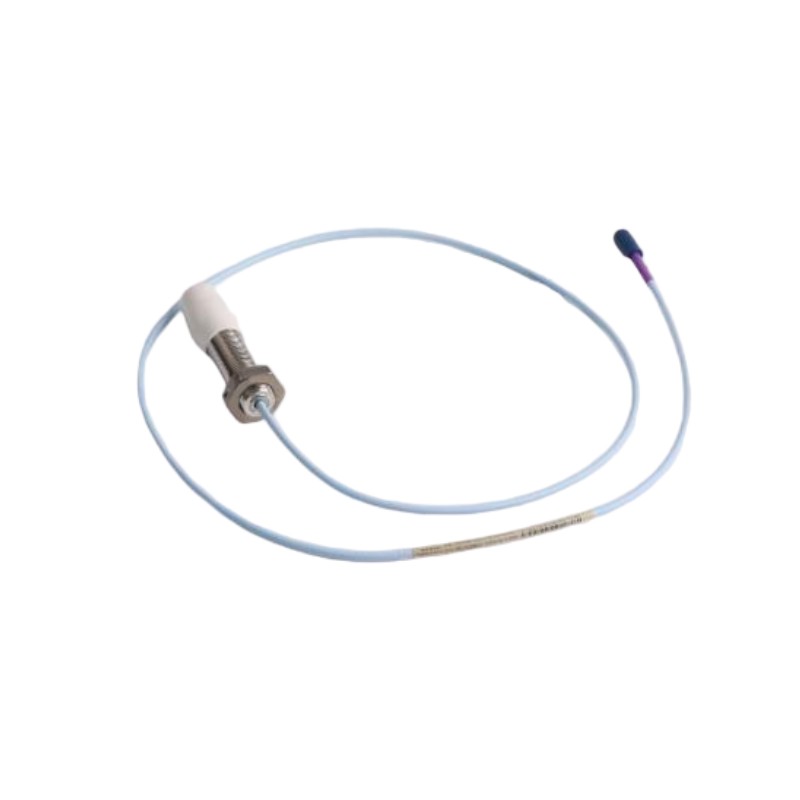
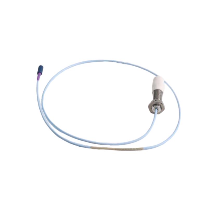
| Proximity Probe | Measures shaft displacement |
| Proximitor/Signal Conditioner | Provides probe interface and signal conditioning |
| Vibration Transducer | Measures machine vibration |
| Speed/Keyphasor Sensor | Provides rotational reference |
| Monitoring Module | Processes and evaluates signals |
| Relay Module | Provides alarm or trip outputs |
| Communication Interface | Transfers monitoring data |
| Engineering Software | Configuration and diagnostics |
| Operator Interface | Displays machine condition |
The exact equipment depends on the monitoring platform and machine type.
5. Proximity Probe Technology
Proximity probes are commonly used for non-contact measurement of rotating shafts.
A probe generates an electromagnetic field and detects changes caused by the distance between the probe tip and the conductive target.
The resulting signal can be used to determine shaft position and dynamic movement.
This makes proximity probes particularly useful for:
- Turbines
- Compressors
- Pumps
- Gearboxes
- Generators
- Large rotating machinery
6. Shaft Vibration Measurement
A rotating shaft does not normally remain perfectly stationary.
It moves dynamically within the bearing system.
Proximity probes can detect this movement.
Two probes installed approximately perpendicular to each other can provide information about shaft motion in two radial directions.
This allows engineers to evaluate the rotor’s dynamic behavior.
7. Axial Position Measurement
Axial displacement is another important parameter for large rotating machines.
A thrust-bearing problem or rotor movement may cause the shaft to move axially beyond acceptable limits.
An axial-position monitoring system can detect this movement.
A simplified arrangement is:
Axial Probe → Signal Conditioner → Monitor → Alarm/Trip
This function is especially important on turbines and other machines where excessive axial movement can result in severe mechanical damage.
8. Keyphasor and Speed Measurement
A rotational reference signal is useful for advanced vibration analysis.
A once-per-revolution reference allows the monitoring system to determine:
- Rotational speed
- Phase
- Shaft position reference
- Vibration phase relationships
The signal is commonly generated by a dedicated reference sensor.
This information can be valuable when analyzing rotor dynamic behavior.
9. Vibration Sensors
Different machine designs require different sensor technologies.
Potential sensor types include:
- Proximity probes
- Accelerometers
- Velocity sensors
- Seismic sensors
- Speed sensors
The sensor should be selected according to the machine structure and measurement objective.
10. Proximity Probe Installation
Probe installation requires careful mechanical alignment.
Important factors include:
- Probe gap
- Probe orientation
- Mounting rigidity
- Target material
- Cable routing
- Environmental conditions
The probe should be securely mounted so that the sensor itself does not move relative to the machine.
Otherwise, sensor movement can be interpreted as machine vibration.
11. Probe Gap
The gap between the probe tip and shaft is critical.
If the gap is incorrect, the output may fall outside the intended operating range.
During commissioning, the technician should verify the probe gap using the appropriate measurement method.
The correct gap depends on the specific probe and system configuration.
It should always be established according to the applicable equipment documentation rather than using a generic value.
12. Probe Orientation
For radial vibration monitoring, two probes are often installed in different radial directions.
The purpose is to observe shaft movement from two axes.
The orientation should be documented clearly.
For example:
- X-axis probe
- Y-axis probe
This information becomes important when interpreting vibration data.
13. Sensor Cable Installation
Sensor cables should be routed carefully.
Avoid unnecessary proximity to:
- High-voltage cables
- Motor power cables
- Variable frequency drive cables
- Large transformers
- High-current conductors
Electromagnetic interference can affect sensitive measurement signals.
Cable shielding and grounding should follow the monitoring system’s installation requirements.
14. Signal Conditioning
The raw sensor signal may require conditioning before it reaches the monitoring electronics.
Signal conditioning can provide functions such as:
- Power to the sensor
- Signal conversion
- Filtering
- Linearization
- Signal amplification
- Interface adaptation
The signal-conditioning component must match the sensor type.
15. Monitoring Modules
Monitoring modules receive the conditioned signal and evaluate machine behavior.
Depending on the system, monitoring functions may include:
- Radial vibration
- Axial position
- Differential expansion
- Speed
- Eccentricity
- Overspeed
- Other machine parameters
The module compares measurements with configured alarm limits.
16. Alarm Levels
Machinery monitoring systems often use multiple alarm levels.
A simplified concept is:
Normal
Machine operating within expected conditions.
Alert
A parameter has exceeded a predefined warning threshold.
Danger
A parameter has reached a more serious threshold and may require immediate action.
The actual terminology and logic depend on the monitoring system configuration.
17. Relay Outputs
Protection systems may provide relay outputs that can be connected to external equipment.
Potential applications include:
- Alarm annunciation
- Control system input
- Emergency shutdown system
- Trip circuits
The relay logic should be tested carefully during commissioning.
A monitoring system that detects a dangerous vibration condition but does not correctly communicate the condition to the protection system cannot provide the intended level of machine protection.
18. Installation of the Monitoring Rack
For rack-based monitoring systems, the installation environment is important.
Consider:
- Cabinet ventilation
- Power supply
- Grounding
- Rack configuration
- Module placement
- Communication connections
- Environmental temperature
The rack should be installed in a suitable industrial enclosure.
19. Power Supply
The monitoring system requires a stable power source.
Before energizing the equipment, verify:
- Supply voltage
- Polarity where applicable
- Grounding
- Fuse/protection
- Power distribution
- Redundant supply arrangement if used
A power problem can create symptoms that appear to be sensor or module faults.
20. Grounding
Correct grounding is essential for sensitive vibration signals.
Poor grounding may produce:
- Electrical noise
- Signal instability
- False alarms
- Communication problems
Grounding should be designed consistently across the monitoring cabinet and machine instrumentation system.
21. Commissioning Procedure
A structured commissioning procedure reduces the risk of false alarms.
Step 1 — Mechanical Inspection
Verify:
- Probe mounting
- Sensor position
- Cable installation
- Connector condition
Step 2 — Electrical Inspection
Check:
- Power supply
- Grounding
- Shielding
- Wiring
Step 3 — Sensor Verification
Confirm that each sensor produces the expected signal.
Step 4 — Configuration
Configure:
- Channel assignments
- Measurement ranges
- Alarm thresholds
- Relay logic
Step 5 — Functional Testing
Test alarms, communication and protection outputs.
22. Sensor Loop Testing
Each sensor should be checked independently.
For a proximity probe system:
Probe → Cable → Signal Conditioner → Monitor
The technician should verify that each stage is operating correctly.
A problem at any point in the chain can result in an incorrect vibration value.
23. Machine Startup Commissioning
During initial machine startup, vibration should be observed continuously.
Important parameters may include:
- Overall vibration
- Shaft position
- Speed
- Phase
- Axial movement
Engineers should compare measurements with expected machine behavior.
24. Baseline Vibration
A baseline is extremely valuable for future diagnostics.
After a machine has reached stable operation, record:
- Vibration amplitude
- Speed
- Load
- Bearing condition
- Temperature
- Axial position
Future measurements can then be compared with the baseline.
25. Why Trending Is Important
A single vibration measurement tells you what is happening at one moment.
A trend tells you how the machine is changing.
For example:
2.1 mm/s → 2.3 mm/s → 2.7 mm/s → 3.1 mm/s
A gradual increase may be more significant than one isolated measurement.
Trend analysis is therefore an important part of predictive maintenance.
26. Common Causes of Increasing Vibration
An increase in vibration can have many possible causes.
Potential mechanical causes include:
- Rotor imbalance
- Misalignment
- Mechanical looseness
- Bearing degradation
- Coupling problems
- Shaft problems
- Resonance
- Rub conditions
The vibration data should be interpreted together with machine operating conditions.
27. Troubleshooting High Vibration
When high vibration is detected, do not immediately assume that the sensor is defective.
Use a structured diagnostic approach.
Step 1
Confirm the machine operating condition.
Step 2
Check the vibration trend.
Step 3
Compare multiple measurement channels.
Step 4
Check speed and load.
Step 5
Verify the sensor signal.
Step 6
Inspect mechanical conditions.
This prevents unnecessary sensor replacement.
28. Troubleshooting False Vibration Alarms
A false alarm may result from:
- Incorrect alarm threshold
- Sensor installation problem
- Cable issue
- Electrical interference
- Configuration error
- Actual transient machine behavior
The first question should be:
Is the machine actually vibrating abnormally, or is the measurement system producing an abnormal signal?
Independent verification can help distinguish the two.
29. Troubleshooting a Failed Proximity Probe
Possible symptoms include:
- No output
- Constant output
- Unstable signal
- Incorrect gap voltage
- Unexpected vibration reading
Check:
- Probe installation
- Probe gap
- Cable continuity
- Connector
- Signal conditioner
- Monitoring channel
30. Troubleshooting Signal Conditioner Problems
If the probe is healthy but the monitor receives an incorrect signal, investigate the signal-conditioning stage.
Potential problems include:
- Incorrect wiring
- Power supply problem
- Damaged cable
- Signal-conditioning hardware failure
- Configuration mismatch
Replacing the monitor without checking the upstream sensor circuit may not solve the problem.
31. Troubleshooting Communication Problems
A modern machinery monitoring system may communicate with higher-level control systems.
If communication fails, investigate:
- Power
- Network connection
- Communication module
- Configuration
- Addressing
- Network equipment
- Software settings
Local machine protection functions should also be checked independently where applicable.
32. Troubleshooting Axial Position Alarms
When an axial-position alarm occurs, engineers should consider both instrumentation and mechanical causes.
Possible causes include:
Instrumentation
- Probe gap problem
- Cable problem
- Sensor failure
- Configuration problem
Mechanical
- Thrust-bearing issue
- Rotor movement
- Process-related force
- Mechanical damage
Because axial movement can be critical, abnormal readings should be investigated promptly.
33. Troubleshooting Speed Signals
Incorrect speed measurements can affect multiple monitoring functions.
Possible causes include:
- Sensor alignment
- Incorrect target
- Wiring
- Signal conditioning
- Configuration
A speed signal should be verified independently before interpreting other machine measurements.
34. Monitoring Turbines
Turbines require comprehensive machinery protection.
Potential measurements include:
- Radial vibration
- Axial position
- Speed
- Eccentricity
- Differential expansion
- Bearing condition
The exact measurement set depends on turbine design.
35. Monitoring Compressors
Large compressors are sensitive to vibration and rotor dynamic problems.
Monitoring may include:
- Shaft vibration
- Axial position
- Speed
- Bearing vibration
- Process-related operating information
Trend analysis can help maintenance teams identify changes in compressor behavior.
36. Monitoring Pumps
Industrial pumps may experience:
- Imbalance
- Misalignment
- Cavitation
- Bearing problems
- Mechanical looseness
Vibration monitoring can provide useful information for identifying changes in pump condition.
However, vibration should always be evaluated together with:
- Flow
- Pressure
- Speed
- Temperature
- Process conditions
37. Monitoring Motors
Large motors can also benefit from condition monitoring.
Potential measurements include:
- Bearing vibration
- Shaft vibration
- Temperature
- Speed
The monitoring approach depends on motor size and criticality.
38. Bearing Condition
Bearings are common sources of mechanical problems.
A developing bearing problem may produce changes in:
- Vibration amplitude
- Frequency content
- Temperature
- Operating noise
Combining vibration and temperature information can improve the diagnostic picture.
39. Imbalance
Rotor imbalance is one possible cause of increased vibration.
If the rotor mass distribution is uneven, centrifugal forces increase as speed rises.
This may produce a speed-related vibration pattern.
However, imbalance should not be diagnosed solely from one overall vibration value.
Frequency and phase information can provide additional evidence.
40. Misalignment
Coupling misalignment can create vibration and mechanical stress.
Potential contributors include:
- Poor shaft alignment
- Thermal growth
- Coupling problems
- Foundation movement
If vibration increases after equipment installation or maintenance, alignment should be considered.
41. Mechanical Looseness
Loose components can produce abnormal vibration.
Potential sources include:
- Loose mounting bolts
- Loose bearing housings
- Structural problems
- Coupling issues
Physical inspection is important when looseness is suspected.
42. Resonance
Every mechanical structure has natural frequencies.
If machine excitation approaches a structural resonance, vibration can increase significantly.
This can create a condition where vibration changes dramatically with speed.
Understanding machine operating speed and structural characteristics can help engineers investigate resonance-related problems.
43. Condition Monitoring Strategy
A strong condition-monitoring strategy generally includes:
Continuous Monitoring
Important machines are monitored continuously.
Trending
Historical data is retained.
Alarm Management
Abnormal values generate notifications.
Diagnostic Analysis
Engineers investigate changes.
Maintenance Planning
Maintenance is scheduled based on evidence.
This is more efficient than relying exclusively on fixed maintenance intervals.
44. Predictive Maintenance
Bently Nevada monitoring technology can be incorporated into predictive-maintenance strategies.
A typical workflow is:
Continuous Measurement
↓
Trend Analysis
↓
Abnormal Pattern
↓
Engineering Review
↓
Maintenance Planning
↓
Inspection or Repair
The objective is to identify developing problems before catastrophic failure.
45. Integration With DCS and PLC Systems
Machinery monitoring systems can exchange selected information with plant control systems.
Common data may include:
- Vibration status
- Alarm state
- Machine speed
- Axial position
- Equipment trip status
The machinery protection system should maintain clearly defined responsibilities separate from ordinary process control logic.
46. Integration With SCADA
SCADA systems can display:
- Machine status
- Alarm information
- Trend data
- Vibration values
- Maintenance information
This gives operators a broader view of plant equipment.
47. Data Historian Integration
Long-term data storage can help engineers identify gradual equipment changes.
For example:
A machine may operate normally for several months while vibration slowly increases.
Without historical data, this trend may be difficult to identify.
With historical data, the change becomes visible.
48. Alarm Threshold Management
Alarm thresholds should be based on:
- Machine design
- Manufacturer recommendations
- Historical operating behavior
- Process conditions
- Engineering analysis
Thresholds should not be changed simply to eliminate nuisance alarms.
If an alarm repeatedly occurs, the underlying cause should be investigated.
49. Maintenance After a Trip
If a machinery protection system trips equipment, maintenance personnel should not simply reset the system and restart the machine.
First determine:
- Which channel generated the trip?
- What was the measured value?
- What was machine speed?
- What was the process load?
- Was the signal credible?
- Were other channels abnormal?
- Is there evidence of mechanical damage?
Only after appropriate investigation should restart decisions be made.
50. Sensor Replacement
When replacing a vibration sensor, verify:
- Correct model
- Correct cable
- Correct connector
- Correct installation position
- Correct gap
- Correct channel configuration
After replacement, perform a complete loop check.
51. Monitoring System Replacement
Replacing a monitoring module requires more than removing the old module and inserting a new one.
Engineers should verify:
- Hardware compatibility
- Firmware compatibility where applicable
- Configuration
- Channel assignment
- Alarm settings
- Relay logic
- Communication
- Calibration
A replacement should be fully tested before returning the machine to normal operation.
52. Recommended Maintenance Schedule
A practical maintenance program may include:
Daily or Continuous
- Monitor alarms
- Review abnormal trends
Periodic
- Inspect sensor wiring
- Check cabinet condition
- Review diagnostic status
Planned Shutdown
- Inspect probes
- Verify mounting
- Check cables
- Validate monitoring channels
The actual schedule should depend on machine criticality and operating environment.
53. Environmental Considerations
Machinery monitoring equipment may operate in environments containing:
- Heat
- Vibration
- Humidity
- Dust
- Oil
- Chemicals
The monitoring cabinet and field sensors should be selected and installed according to environmental requirements.
Sensor cables should also be protected from mechanical damage.
54. Documentation Requirements
Good documentation is essential for machinery protection systems.
Recommended documentation includes:
- Sensor location drawings
- Probe gap records
- Wiring diagrams
- Channel assignments
- Alarm settings
- Relay logic
- Network configuration
- Baseline vibration data
- Maintenance records
This information significantly improves future troubleshooting.
55. Sensor Tagging
Every sensor should have a unique identification.
For example:
| Tag | Measurement |
|---|---|
| XV-101 | Radial Vibration X |
| YV-101 | Radial Vibration Y |
| AP-101 | Axial Position |
| KS-101 | Keyphasor |
| SP-101 | Speed |
The actual naming convention should match the plant’s engineering standards.
56. Common Installation Mistakes
Incorrect Probe Gap
Can produce unreliable measurements.
Poor Mechanical Mounting
Can allow sensor movement.
Improper Cable Routing
Can introduce electrical interference.
Incorrect Channel Assignment
Can cause incorrect machine identification.
Incorrect Alarm Configuration
Can cause nuisance alarms or insufficient protection.
Incomplete Commissioning
Can leave faults undiscovered until production operation.
57. Common Troubleshooting Mistakes
One of the most common mistakes is replacing hardware before confirming the fault.
For example:
High Vibration → Replace Monitor
This is not necessarily the correct approach.
A better process is:
High Vibration → Verify Signal → Verify Sensor → Check Trend → Check Operating Condition → Inspect Machine
This method reduces unnecessary hardware replacement.
58. Recommended Troubleshooting Flow
A practical troubleshooting sequence is:
Alarm
↓
Identify Channel
↓
Check Measurement
↓
Check Sensor
↓
Check Wiring
↓
Check Signal Conditioner
↓
Check Monitor
↓
Check Configuration
↓
Check Machine
This approach helps separate instrumentation faults from genuine mechanical problems.
59. Benefits of Bently Nevada Monitoring Technology
A properly designed machinery monitoring system can provide:
Early Warning
Changes in vibration can be detected before severe failure.
Machine Protection
Critical measurements can initiate alarms or protective actions.
Continuous Monitoring
Important equipment can be monitored while operating.
Historical Analysis
Trend information supports maintenance planning.
Reduced Unplanned Downtime
Early detection can provide more time for intervention.
Better Maintenance Decisions
Maintenance can be based on machine condition rather than assumptions alone.
60. Final Engineering Recommendations
When installing or maintaining a Bently Nevada machinery monitoring system:
- Select sensors according to the machine.
- Install probes with correct mechanical alignment.
- Verify probe gaps carefully.
- Keep sensor cables properly routed.
- Use appropriate shielding and grounding.
- Verify every monitoring channel.
- Establish a reliable baseline.
- Trend vibration continuously where appropriate.
- Investigate alarms rather than simply resetting them.
- Separate instrumentation faults from mechanical faults.
- Maintain accurate alarm and relay documentation.
- Keep configuration backups.
- Test protection functions during planned maintenance.
- Review historical trends before major maintenance decisions.
- Treat abnormal machine-protection indications as potentially significant until verified.
Frequently Asked Questions
What is Bently Nevada used for?
Bently Nevada technology is primarily associated with monitoring and protecting rotating machinery. Applications include turbines, compressors, pumps, generators and other critical rotating equipment.
What does a proximity probe measure?
A proximity probe can measure the relative movement or position of a rotating shaft without physically contacting the shaft.
Why are two radial probes commonly used?
Two probes installed in different radial directions can provide information about shaft movement along two axes.
What is Keyphasor used for?
A Keyphasor or rotational reference signal provides a once-per-revolution reference that can be used for speed and phase-related vibration analysis.
What can cause a high vibration alarm?
Possible causes include imbalance, misalignment, mechanical looseness, bearing problems, resonance, process changes, sensor problems or electrical interference.
Should a vibration monitor be replaced when an alarm occurs?
Not automatically. The sensor, wiring, signal-conditioning equipment, configuration and actual machine condition should be checked before replacing the monitoring module.
Why is baseline vibration important?
A baseline establishes normal machine behavior. Future measurements can then be compared against the baseline to identify changes.
Can machinery monitoring data be integrated into a PLC or DCS?
Selected monitoring information can generally be integrated into higher-level automation systems, depending on the monitoring platform and communication architecture.
Is vibration monitoring enough for predictive maintenance?
Vibration is an important condition-monitoring parameter, but a complete predictive-maintenance strategy may also consider temperature, speed, load, process conditions, lubrication and other machine-specific information.
Conclusion
Bently Nevada machinery monitoring systems play an important role in protecting critical rotating equipment and supporting predictive maintenance strategies.
A reliable installation begins with correct sensor selection and mechanical installation. Proximity probes must be positioned accurately, cables must be installed appropriately, signal-conditioning equipment must match the sensors, and monitoring channels must be configured correctly.
After installation, commissioning should include complete sensor loop checks, alarm verification, relay testing and baseline measurement.
During operation, engineers should focus not only on individual vibration values but also on trends, operating conditions, speed, load and relationships between multiple measurement channels.
When abnormal vibration occurs, the correct approach is systematic troubleshooting rather than immediate hardware replacement.
The complete diagnostic path should include:
Machine → Sensor → Cable → Signal Conditioning → Monitoring Module → Alarm/Relay → Control System
By maintaining this complete signal chain and combining continuous monitoring with historical trend analysis, industrial plants can improve equipment visibility, identify developing mechanical problems earlier and make maintenance decisions based on actual machine behavior.
For turbines, compressors, pumps, generators and other critical rotating assets, a properly engineered Bently Nevada monitoring architecture can therefore serve two complementary purposes: protecting machinery from severe operating conditions and providing valuable information for long-term equipment health management.