
NewsNEWCENTER
Featured products
Contact Us
Allen Bradley 1606-XLDC92D DC/DC Converter Troubleshooting Guide
2026-08-26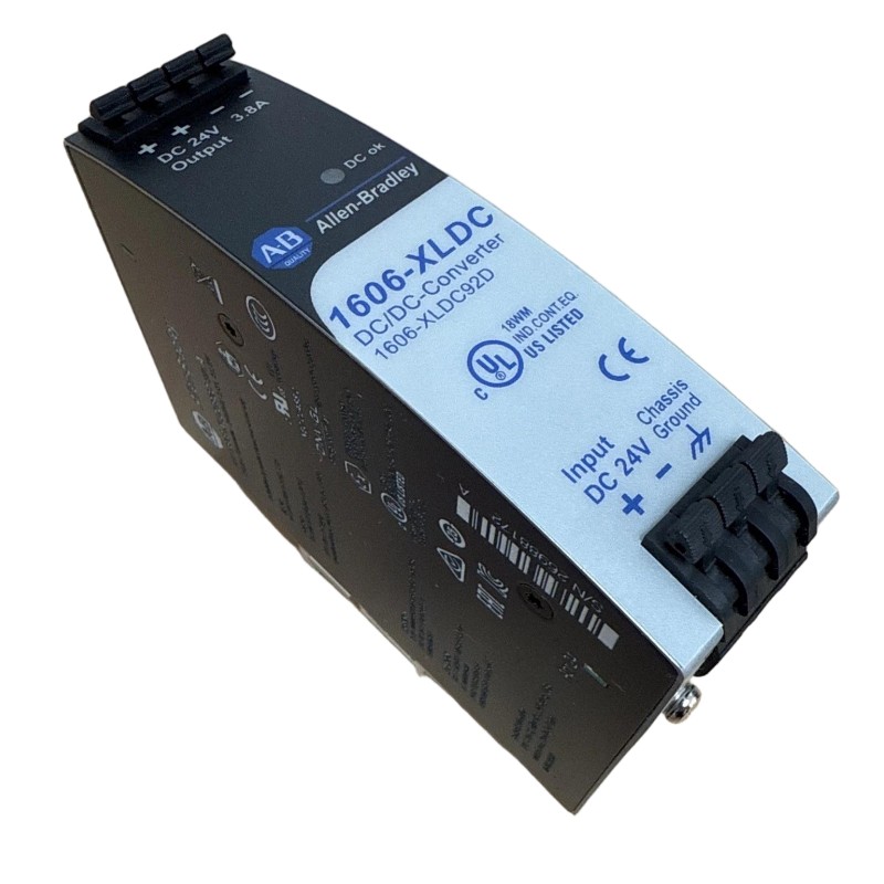
Table of Contents
- Allen Bradley 1606-XLDC92D Troubleshooting Starting Point
- Allen Bradley 1606-XLDC92D DC/DC Converter Fault Symptoms
- Allen Bradley 1606-XLDC92D Fault Diagnosis Thinking Process
- Allen Bradley 1606-XLDC92D Input-Side Troubleshooting
- Allen Bradley 1606-XLDC92D Output-Side Fault Diagnosis
- Allen Bradley 1606-XLDC92D Load and Distribution Faults
- Allen Bradley 1606-XLDC92D Real Troubleshooting Case
- Allen Bradley 1606-XLDC92D Repair and Replacement Decision
- Allen Bradley 1606-XLDC92D Post-Repair Verification
- Allen Bradley 1606-XLDC92D Troubleshooting FAQ
- Allen Bradley 1606-XLDC92D Overall Fault Diagnosis Summary
Allen Bradley 1606-XLDC92D Troubleshooting Starting Point
Allen Bradley 1606-XLDC92D troubleshooting should begin by identifying whether the abnormal condition exists on the input side, inside the DC/DC conversion stage, or downstream in the load circuit. A PLC Controller reset or Module dropout does not by itself prove that the converter has failed.
The most effective Fault Diagnosis approach is to establish a normal electrical baseline, reproduce the failure, and compare measurements at several points. This is particularly important for intermittent faults that disappear when the machine is restarted.
Allen Bradley 1606-XLDC92D DC/DC Converter Fault Symptoms
Several automation symptoms can be associated with an unstable DC/DC conversion system:
- PLC Controller resets unexpectedly.
- Remote I/O Modules disconnect or restart.
- Communication interfaces repeatedly lose connection.
- Sensors produce unstable readings.
- Control circuits drop out during load transitions.
- Output voltage falls when the connected load increases.
- The converter appears normal with no load but fails under operating load.
- Faults appear after cabinet temperature increases.
Allen Bradley 1606-XLDC92D Fault Timing as Diagnostic Evidence
The timing of the failure should be recorded. A fault that occurs immediately when a branch is energized suggests a different cause from a fault that appears only after several hours of operation.
If the PLC resets at the exact moment a motor-control interface, solenoid circuit, or communication device becomes active, investigate the DC power response during that event.
Allen Bradley 1606-XLDC92D Fault Diagnosis Thinking Process
A practical diagnostic model is to treat the 1606-XLDC92D system as a sequence of electrical boundaries. At each boundary, determine whether the expected voltage and behavior remain present.
FAULT DIAGNOSIS

DC INPUT
   |
   |  Is input stable?
   v
1606-XLDC92D
   |
   |  Is converted output stable?
   v
DC DISTRIBUTION
   |
   |  Is load-side voltage stable?
   v
PLC / MODULE / SENSOR
   |
   |  Does the individual device remain healthy?
   v
SYSTEM OPERATION
The diagnostic direction changes depending on the measurement. If the input is already abnormal, there is little value in replacing the converter before the upstream problem is corrected. If the converter output is stable but the remote load is abnormal, investigate distribution wiring instead.
Allen Bradley 1606-XLDC92D Input-Side Troubleshooting
The first measurement should confirm that the converter receives the expected DC source under the same conditions in which the fault occurs.
Check the source during normal operation and during the event. A supply may appear correct with the machine idle but experience a transient reduction when another DC load switches on.
Allen Bradley 1606-XLDC92D Input Fault Indicators
- Unexpected variation in input DC voltage.
- Loose input terminals.
- Incorrect polarity or wiring changes.
- Undersized or overloaded upstream conductors.
- Protection device operation.
- Voltage disturbance caused by another connected load.
Input-side Troubleshooting should always precede conclusions about converter failure because the converter can only regulate its output within the conditions supported by its design.
Allen Bradley 1606-XLDC92D Output-Side Fault Diagnosis
Once the input is verified, measure the 1606-XLDC92D output. Compare the result with the commissioning baseline and repeat the measurement while the connected load changes.
A useful diagnostic distinction is between an abnormal output with minimal load and an output that becomes abnormal only when the load increases. The first pattern points toward the converter or its input conditions. The second requires careful examination of load current, distribution wiring, and possible downstream faults.
OUTPUT TEST LOGIC

Measure output at light load
        |
        v
Is output stable?
   |             |
  YES            NO
   |             |
Add load       Check input,
progressively  wiring and
   |            converter
   v
Output changes?
   |
   +---- YES ---> investigate load/current/distribution
   |
   +---- NO ----> continue system validation
Allen Bradley 1606-XLDC92D Load and Distribution Faults
Downstream faults are often overlooked because the converter is the most visible component in the circuit. A shorted field device, excessive load, poor terminal connection, or undersized conductor can all produce symptoms that look like converter failure.
Common Allen Bradley 1606-XLDC92D Downstream Fault Causes
- Excessive load: the actual connected current is higher than the original calculation.
- Downstream short circuit: damaged field wiring or equipment pulls down the converted DC supply.
- High-resistance connection: a poor terminal creates increasing voltage drop as current rises.
- Long distribution cable: cable resistance reduces voltage at remote loads.
- System modification: additional PLC, Module, communication, or Sensor equipment changes the original load.
- Thermal condition: the fault appears only after the cabinet reaches operating temperature.
When investigating a suspected downstream problem, isolate branches systematically rather than disconnecting multiple circuits at once. A controlled isolation process provides much stronger diagnostic evidence.
Allen Bradley 1606-XLDC92D Real Troubleshooting Case
In one field Troubleshooting case, a PLC Controller remained operational during cabinet startup but restarted when a group of remote control devices was energized. The maintenance team initially suspected the 1606-XLDC92D because the converter supplied the affected branch.
The engineer first measured the input and output with the system idle. The converter produced a stable output, so the next test was performed while reproducing the exact load transition that caused the PLC restart.
During the event, the converter output showed only a small change, while the voltage measured at the remote distribution point fell from approximately 24 VDC to approximately 22.4 VDC.
The difference between these two measurement points was the critical clue. The converter was not showing the same magnitude of voltage disturbance as the remote load.
Inspection of the branch identified a poor terminal connection. Under normal low-current conditions, the connection appeared acceptable. When several devices became active simultaneously, the increased current caused additional voltage drop across the defective connection.
After the connection was corrected, the automatic load transition was repeated several times. The PLC remained stable and the remote equipment no longer restarted.
The diagnostic conclusion was therefore that the original converter was not the root cause. The failure originated in the downstream DC distribution path.
Allen Bradley 1606-XLDC92D Repair and Replacement Decision
Replacement of the Allen Bradley 1606-XLDC92D should be considered only after the input source, wiring, connected load, and downstream distribution have been investigated.
If the converter output remains abnormal with a verified input and appropriately controlled load condition, the converter becomes a reasonable suspect. If the output is stable but a specific branch fails, repair should focus on that branch rather than replacing the conversion equipment.
Allen Bradley 1606-XLDC92D Corrective Action Rules
- Do not bypass protective devices.
- Do not repeatedly energize a suspected short circuit.
- Verify polarity before reconnection.
- Inspect terminals after overload or thermal events.
- Document measured values before hardware replacement.
- Use the approved replacement procedure if the converter is determined to be faulty.
Allen Bradley 1606-XLDC92D Post-Repair Verification
After corrective work, repeat the exact operating sequence that caused the original fault. If the problem occurred during a load transition, reproduce that transition. If the problem occurred after prolonged operation, perform the final verification under a representative thermal condition.
Allen Bradley 1606-XLDC92D Recovery Checks
- Confirm stable DC input.
- Confirm stable converter output.
- Compare converter voltage with remote load voltage.
- Check PLC Controller operation.
- Check I/O Module availability.
- Check communication interfaces.
- Check Sensor behavior.
- Repeat the original fault-producing sequence.
- Record final measurements.
A repair should be considered successful only when the original failure can no longer be reproduced under the relevant operating conditions.
Allen Bradley 1606-XLDC92D Troubleshooting FAQ
Why can an Allen Bradley 1606-XLDC92D fault appear as a PLC Controller problem?
The PLC Controller may be the first device to react when the converted DC supply becomes unstable. The PLC reset is therefore a symptom that requires investigation of the complete power path.
What should be measured first during 1606-XLDC92D Fault Diagnosis?
Verify the DC input and then measure the converter output. After that, compare the voltage at the main distribution point and the affected downstream equipment.
Why can the converter output look normal while a remote Module fails?
Voltage drop can occur between the converter and the Module because of cable resistance, poor terminals, or excessive branch loading. Measuring only at the converter can therefore miss a downstream problem.
When should the 1606-XLDC92D be replaced?
Replacement should be considered when the input and downstream system have been verified and the converter itself continues to demonstrate abnormal output behavior under an appropriate test condition.
How can intermittent 1606-XLDC92D faults be reproduced?
Identify the exact machine sequence, load transition, or operating condition associated with the failure. Reproduce that condition while monitoring input voltage, converter output, and critical load-side voltage.
Allen Bradley 1606-XLDC92D Overall Fault Diagnosis Summary
Allen Bradley 1606-XLDC92D Troubleshooting should be based on measured electrical evidence rather than on the first PLC or Module alarm observed. A DC/DC converter fault can originate from the input source, conversion stage, distribution wiring, or downstream load.
The most effective Fault Diagnosis method is to establish a baseline, reproduce the failure, measure the system at multiple boundaries, isolate suspect branches, and determine where the abnormal voltage condition begins. This approach is especially useful for intermittent PLC resets and communication faults.
After Repair or corrective action, repeat the original operating sequence and document the final measurements. A reliable commissioning baseline makes future Installation, Setup, Troubleshooting, and maintenance of the Allen Bradley 1606-XLDC92D and its connected industrial automation equipment significantly more efficient.