
NewsNEWCENTER
Featured products
Contact Us
Allen Bradley 1606-XLDC92D DC/DC Converter Installation Guide
2026-08-26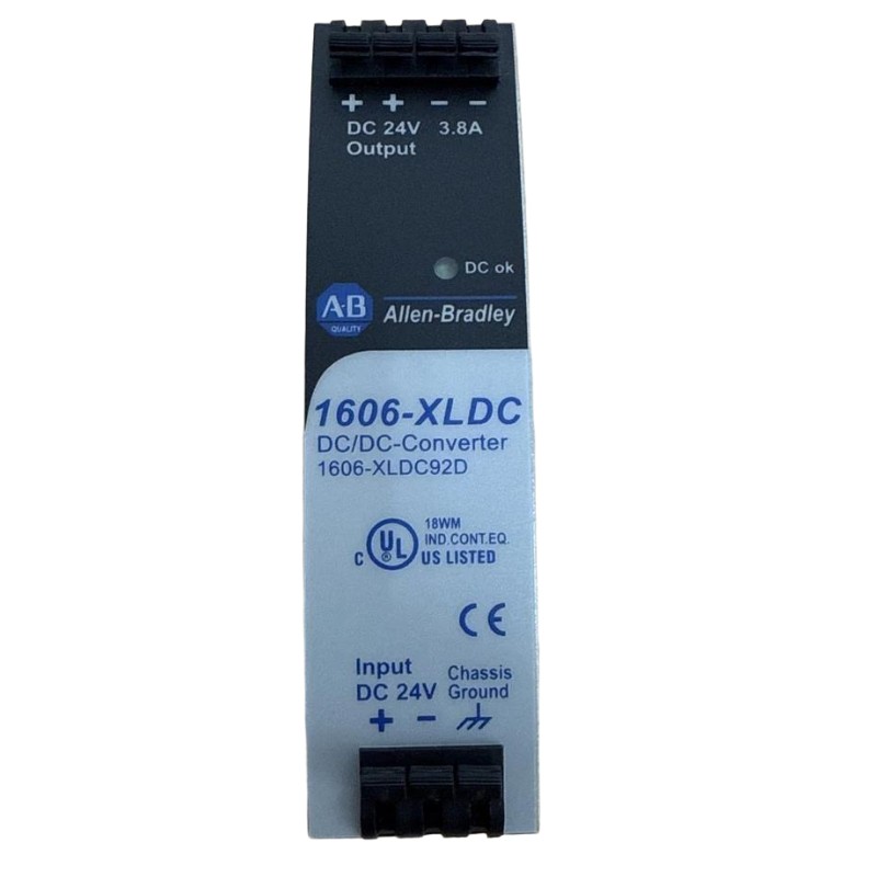
Table of Contents
- Allen Bradley 1606-XLDC92D DC/DC Converter Installation Overview
- Allen Bradley 1606-XLDC92D DC/DC Converter Role in Control Systems
- Allen Bradley 1606-XLDC92D Installation Engineering Review
- Allen Bradley 1606-XLDC92D Mounting and Cabinet Preparation
- Allen Bradley 1606-XLDC92D Wiring and Polarity Verification
- Allen Bradley 1606-XLDC92D Setup and Initial Power Checks
- Allen Bradley 1606-XLDC92D Commissioning and System Configuration
- Allen Bradley 1606-XLDC92D Output Validation Under Load
- Allen Bradley 1606-XLDC92D Field Commissioning Example
- Allen Bradley 1606-XLDC92D Installation FAQ
- Allen Bradley 1606-XLDC92D Overall Technical Summary
Allen Bradley 1606-XLDC92D DC/DC Converter Installation Overview
Allen Bradley 1606-XLDC92D installation should begin with verification of the DC source, conversion requirements, load characteristics, and grounding arrangement. A DC/DC converter sits between the available DC bus and the downstream control circuit, so incorrect polarity, unsuitable input conditions, poor wiring, or excessive load can affect every PLC Controller, Module, Sensor, or communication device connected to its output.
The 1606-XLDC92D is an Allen Bradley DC/DC Converter intended for industrial control-power applications. Unlike a conventional AC/DC power supply, a DC/DC converter receives an existing DC source and provides the required converted DC supply for the downstream circuit. This makes correct identification of both input and output circuits especially important during Installation and Commissioning.
A good Installation Guide should therefore verify the electrical path in both directions: the input side must provide a suitable DC source, while the output side must deliver stable power to the intended automation loads under realistic operating conditions.
Allen Bradley 1606-XLDC92D DC/DC Converter Role in Control Systems
The 1606-XLDC92D can be integrated into an industrial control architecture where a separate DC voltage conversion stage is required. In practice, the converter may support a dedicated control circuit, instrumentation section, interface equipment, or another DC-powered subsystem.
The engineering advantage of a DC/DC conversion stage is the ability to establish a controlled DC supply from an available DC source. However, the converter does not eliminate the need for correct load calculations or distribution design.
Allen Bradley 1606-XLDC92D Typical Automation Applications
- Industrial PLC Controller power circuits.
- Remote I/O Module power distribution.
- Instrumentation and Sensor circuits.
- Communication interface power.
- Machine control cabinets using multiple DC voltage levels.
- Specialized control subsystems requiring DC voltage conversion.
Before connection, determine whether the 1606-XLDC92D is intended to supply an entire control branch or only a selected group of loads. This decision affects conductor sizing, protection, voltage-drop calculations, and later Troubleshooting.
Allen Bradley 1606-XLDC92D Installation Engineering Review
The first engineering task is to compare the converter’s intended application with the actual electrical drawing. Do not connect the input simply because the available DC voltage appears compatible. Confirm the intended input circuit, output circuit, load requirements, and protection scheme.
Allen Bradley 1606-XLDC92D Pre-Installation Checklist
- Confirm the exact 1606-XLDC92D model.
- Identify the upstream DC source.
- Verify the required conversion arrangement.
- Determine the expected continuous load.
- Identify intermittent and peak loads.
- Review branch protection.
- Check conductor sizing.
- Review cabinet temperature and ventilation.
- Confirm the downstream System Configuration.
Load calculations should include the actual devices that will be connected after Commissioning. A later-added communication module or field interface can change the converter loading significantly compared with the original design.
Allen Bradley 1606-XLDC92D Mounting and Cabinet Preparation
Mount the Allen Bradley 1606-XLDC92D according to the approved cabinet design and applicable installation requirements. The physical location should provide adequate access to the terminals and sufficient space for thermal dissipation.
Keep the converter away from unnecessary heat sources where practical. Drives, contactors, braking equipment, transformers, and other power components can increase the internal cabinet temperature and influence the operating environment of control-power equipment.
Wire ducts should also be arranged so that input and output conductors can be identified and maintained easily. Clear separation makes later Fault Diagnosis substantially faster.
Allen Bradley 1606-XLDC92D Wiring and Polarity Verification
Allen Bradley 1606-XLDC92D wiring should be completed with the applicable power sources isolated in accordance with the site’s electrical safety procedures. The input and output terminals must be identified from the actual product markings and approved documentation before any conductor is connected.
DC polarity must be verified independently. Never rely only on wire color, especially on cabinets that have been modified or rewired in the field.
Allen Bradley 1606-XLDC92D Wiring Inspection Points
- Verify the DC input source.
- Verify positive and negative polarity.
- Confirm the intended output circuit.
- Use conductors appropriate for the calculated load.
- Provide suitable circuit protection.
- Keep input and output wiring clearly identified.
- Inspect terminals for secure mechanical connections.
- Keep sensitive signal wiring away from noisy power circuits where practical.
After termination, perform a point-to-point check against the electrical drawing. This is particularly important when the converter is installed into an existing cabinet rather than a newly manufactured panel.
Allen Bradley 1606-XLDC92D Setup and Initial Power Checks
The Allen Bradley 1606-XLDC92D Setup should begin without the complete downstream load connected when the engineering procedure allows staged energization. The objective is to verify the input circuit and establish an output baseline before the converter is asked to supply the full automation system.
1606-XLDC92D INITIAL SETUP

INPUT
  Verify DC source
  Confirm polarity
  Check protection
       |
       v
CONVERTER
  Energize under approved conditions
  Measure input
  Measure converted output
       |
       v
LOAD
  Connect critical control branch
  Monitor output voltage
  Add remaining loads progressively
If the measured output is abnormal before the downstream load is connected, stop the commissioning process and investigate the input circuit, wiring, and converter condition. If the output becomes abnormal only after a particular branch is connected, investigate the load and distribution path.
Allen Bradley 1606-XLDC92D Commissioning and System Configuration
Commissioning should verify that the 1606-XLDC92D operates correctly within the complete System Configuration. The downstream PLC Controller, I/O Modules, Sensors, and communication devices should be tested under representative operating conditions rather than only in an idle state.
Measure the converted DC output at the converter and at important downstream equipment. A stable reading at the converter does not necessarily mean that a remote load receives the same voltage if the distribution circuit has excessive resistance.
Allen Bradley 1606-XLDC92D Commissioning Measurements
- Input DC voltage.
- Converter output voltage.
- Main distribution voltage.
- Remote load voltage.
- PLC Controller operating status.
- I/O Module status.
- Communication stability.
- Sensor signal stability.
- Output response during representative load changes.
Commissioning records should be retained because they provide a valuable reference for future Troubleshooting. If a fault appears months later, comparison with the original measurements can quickly show whether the electrical condition has changed.
Allen Bradley 1606-XLDC92D Output Validation Under Load
Output validation should be performed with the converter supplying representative equipment. No-load measurements are useful, but they cannot reveal every problem associated with distribution resistance or load-dependent voltage changes.
For example, if the converter output is approximately 24 VDC during a light-load test but a remote control branch falls significantly when several loads operate simultaneously, the investigation should move toward the distribution circuit and load characteristics.
Allen Bradley 1606-XLDC92D Validation Criteria
- Stable input DC source.
- Correct converter output.
- Acceptable voltage at downstream loads.
- No unexpected PLC Controller resets.
- No unexplained I/O Module dropouts.
- Stable Sensor and instrumentation operation.
- Stable communication during normal machine operation.
Allen Bradley 1606-XLDC92D Field Commissioning Example
In one commissioning case, an Allen Bradley control cabinet used a DC/DC conversion stage to supply a dedicated automation branch. The PLC Controller started normally during the initial test, and the converter output appeared stable at the converter terminals.
When the remote control devices were energized, however, a communication interface intermittently restarted. Rather than immediately replacing the 1606-XLDC92D, the engineer compared the converter output with the voltage at the remote distribution point.
The converter-side measurement remained close to the normal operating value, while the remote point showed a noticeable voltage reduction when the branch load increased. The diagnostic boundary therefore moved downstream of the converter.
Inspection found that the branch conductor had been routed through a connection with excessive resistance. The problem was not obvious during the no-load or light-load test because the voltage drop was small at low current.
After correcting the connection, the remote communication interface remained stable during repeated load transitions. The converter itself was not replaced.
This type of field result is important when performing an Allen Bradley 1606-XLDC92D Installation Guide procedure: always validate the output where the equipment actually consumes the power, not only at the converter terminals.
Allen Bradley 1606-XLDC92D Installation FAQ
What is the Allen Bradley 1606-XLDC92D used for?
The 1606-XLDC92D is a DC/DC Converter used within industrial control-power systems to convert an available DC source into the required downstream DC supply arrangement.
Why is polarity verification important during 1606-XLDC92D installation?
DC systems depend on correct polarity. Incorrect connections can damage equipment or create unsafe operating conditions, so polarity should be verified against the approved electrical documentation before energization.
Should the PLC Controller be connected immediately during Setup?
When the commissioning procedure allows staged energization, it is generally useful to establish the converter’s electrical baseline before applying the complete downstream load. This makes abnormal behavior easier to isolate.
Why should output voltage be measured at the remote Module?
The voltage at the converter may differ from the voltage at a remote load because of conductor resistance, terminal connections, and load-dependent voltage drop. Load-side measurement provides a more realistic picture of system performance.
What commissioning information is useful for future Troubleshooting?
Record the input voltage, converter output, important downstream measurements, connected load condition, PLC status, I/O status, communication behavior, and any abnormal voltage changes observed during load transitions.
Allen Bradley 1606-XLDC92D Overall Technical Summary
The Allen Bradley 1606-XLDC92D Installation Guide should focus on the complete DC conversion and distribution system. Correct source identification, polarity, protection, mounting, wiring, load calculation, and System Configuration are essential for reliable operation.
From a field engineering perspective, the most useful Commissioning practice is to compare the converter output with the voltage available at critical downstream loads. This can distinguish an actual converter problem from a distribution or connection problem that produces similar PLC, Module, Sensor, or communication symptoms.
A properly completed Setup should leave documented baseline measurements and a verified operating condition. These records become valuable references for future maintenance, Troubleshooting, and Fault Diagnosis involving the Allen Bradley 1606-XLDC92D and the wider industrial automation power system.