

ProductPRODUCT
Featured products
Contact Us
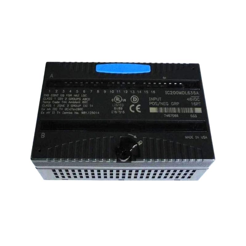
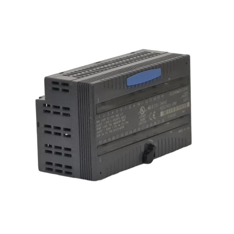
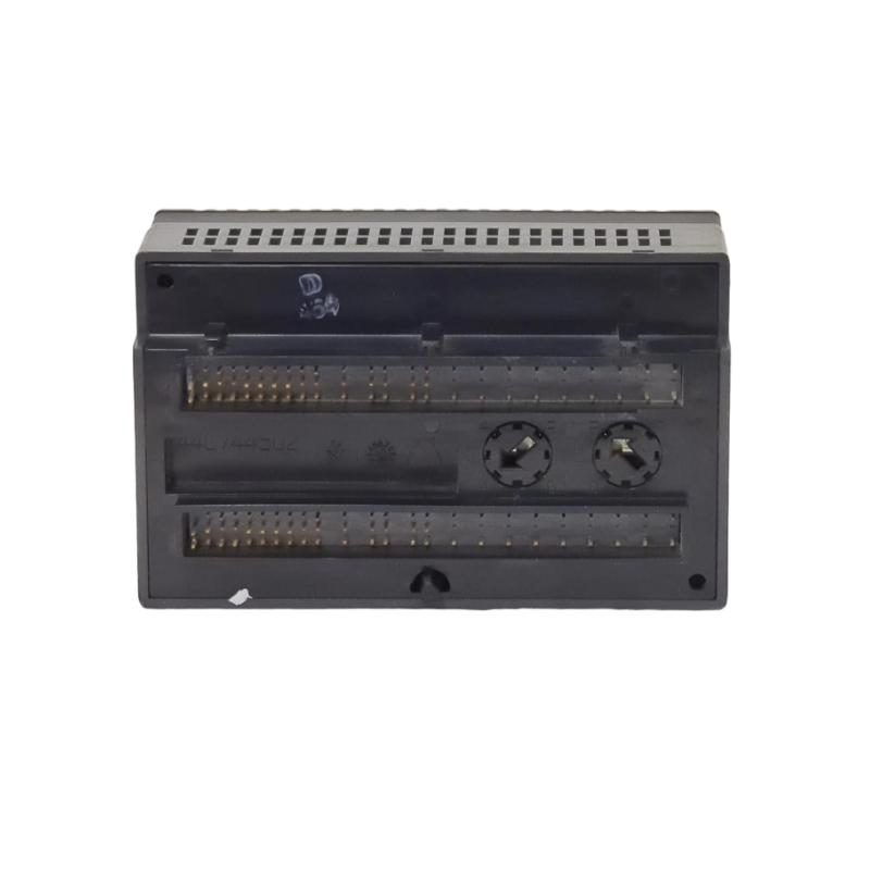
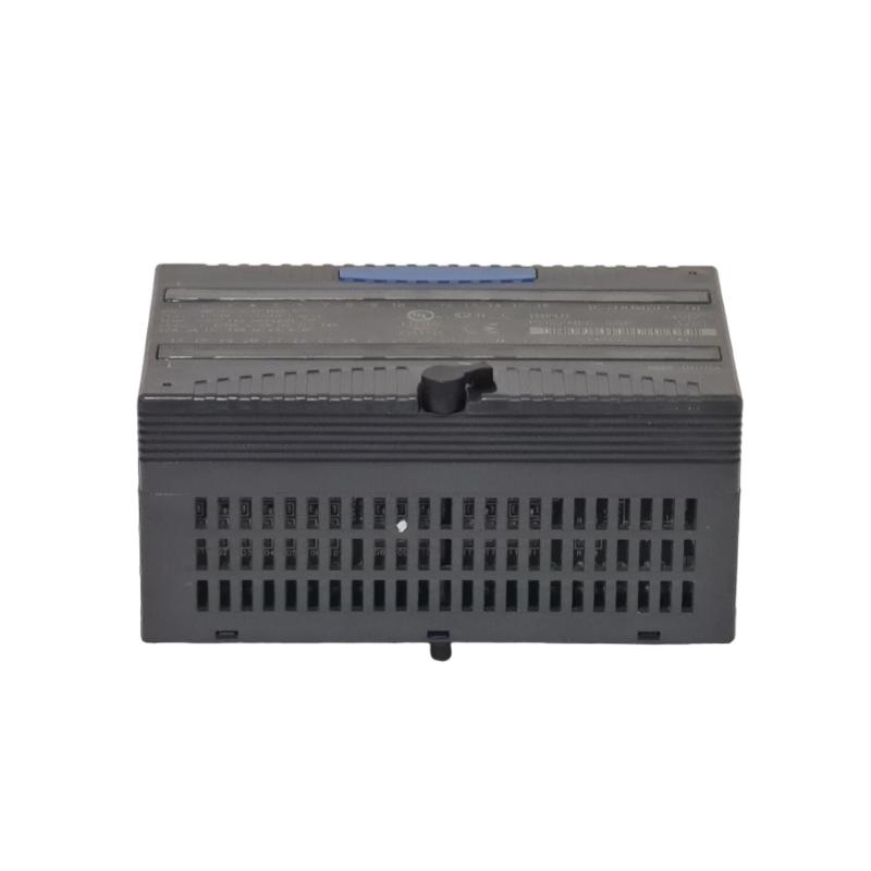
- GE
- IC200MDL635
- VersaMax Discrete Input Module
- USA
- 110 x 66.8 x 50 mm
- 0.136 kg
- Xiamen, China
- New & In Stock
- T/T, PayPal, Western Union
- 1 Year
- 1-3 Working Days
- DHL, UPS, TNT, FedEx and EMS.
- 24-Hour Service
- COO
- 46
Our advantage

Global Logistics
We have a 10-year logistics and express cooperation agreement, so our products can be shipped to any place in the world.

Brand new and original
Our products are imported in bulk from the place of origin. Because of the cooperative relationship, our products are all original and 100% new.

24-hour service
We provide 7*24 hours service to our customers. We will be there whenever you need us.

Price advantage
All our products are priced very favorably because we have our own warehouse and supply.
| Company Information | |||
| [email protected] | |||
| Mobile | +8615980777398 | ||
| +8615980777398 | |||
| 15980777398 |
Product Overview
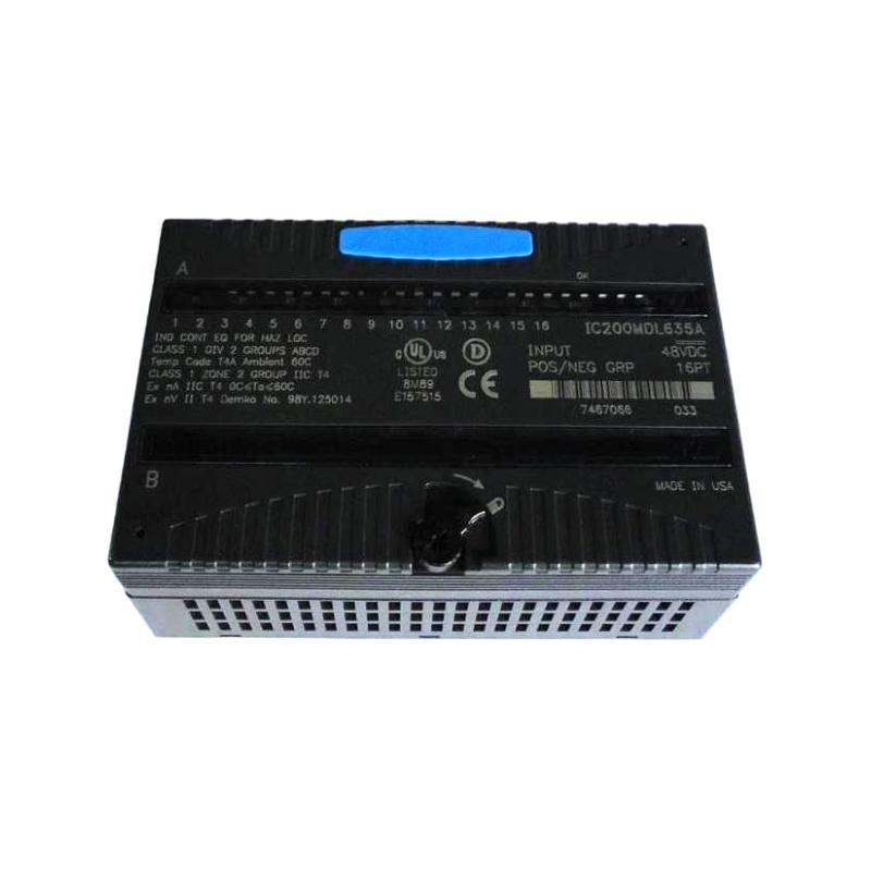
The GE IC200MDL635 VersaMax Discrete Input Module is a modular digital input component used in GE VersaMax industrial automation systems. Its primary purpose is to acquire discrete electrical signals from field devices and transfer their status to the PLC controller for monitoring, sequencing, interlocking, and equipment-status functions.
In an industrial control system, many operating conditions are represented as discrete states. A motor may be running or stopped, a valve may be open or closed, a limit switch may be active or inactive, and a machine guard may be open or closed. The IC200MDL635 provides the input interface needed to bring these binary conditions into the control system.
The module works as part of the VersaMax modular I/O architecture. Its performance depends on correct installation, appropriate field wiring, a properly functioning carrier and backplane, suitable field power, and correct PLC configuration.
The supplied product information is:
- Manufacturer: GE
- Product Family: VersaMax
- Model: IC200MDL635
- Product Type: Discrete Input Module
- Dimensions: 110 × 66.8 × 50 mm
- Weight: 0.136 kg
- Application: Industrial Automation
- Primary Function: Discrete Field Signal Acquisition
The exact electrical input characteristics, channel configuration, voltage requirements, current requirements, isolation characteristics, and terminal arrangement should be verified for the specific installation before field wiring and commissioning.
Technical Specifications
| Parameter | Specification |
|---|---|
| Manufacturer | GE |
| Product Family | VersaMax |
| Model | IC200MDL635 |
| Product Type | VersaMax Discrete Input Module |
| Signal Type | Digital / Discrete Input |
| Main Function | Field Signal Acquisition |
| System Architecture | Modular I/O |
| Application | Industrial Automation |
| Dimensions | 110 × 66.8 × 50 mm |
| Weight | 0.136 kg |
| Installation | VersaMax Modular I/O System |
| Interface | VersaMax I/O Backplane |
| Field Interface | Discrete Field Devices |
| Typical Applications | Sensors, Switches, Contacts, Equipment Feedback |
Function and Working Principle
The IC200MDL635 receives electrical status signals from external field devices and makes those states available to the VersaMax controller.
The basic signal path can be represented as:
Field Sensor / Switch
↓
Field Wiring
↓
IC200MDL635
↓
VersaMax Backplane
↓
Controller
↓
PLC Program
The input module monitors its connected input circuits. When a field device changes state, the associated input circuit detects the corresponding electrical condition.
The controller can then use this information within the PLC program.
For example, a machine may use a limit switch to confirm that a moving assembly has reached its home position. When the limit switch becomes active, the IC200MDL635 receives the signal and provides the input state to the PLC. The control program can then permit the next machine step.
This makes the input module an important part of the signal-acquisition layer of the automation system.
Role in Industrial Control Systems
A typical control architecture using the module may look like:
Field Sensors
↓
IC200MDL635
↓
VersaMax Controller
↓
PLC Logic
↓
Output Modules
↓
Actuators
↓
Machine / Process
The module can provide information used for:
- Machine-position monitoring
- Motor feedback
- Valve-position monitoring
- Equipment-ready signals
- Limit-switch detection
- Alarm monitoring
- Operator commands
- Process permissives
- Interlocking
- Equipment status
Typical Industrial Applications
Machine Automation
The IC200MDL635 can be used to monitor:
- Limit switches
- Proximity sensors
- Pushbuttons
- Selector switches
- Machine-position sensors
- Motor auxiliary contacts
- Equipment-ready signals
The PLC can use these signals to coordinate automatic sequences.
Conveyor Systems
Discrete inputs can monitor:
- Product presence
- Conveyor position
- Motor feedback
- Jam detection
- End-position switches
- Equipment interlocks
The controller can combine these signals with timing and sequence logic.
Packaging Equipment
Potential input signals include:
- Product sensors
- Cylinder-position switches
- Guard status
- Machine-ready feedback
- Limit switches
- Fault contacts
- Operator controls
A reliable input signal is important for maintaining the correct sequence of packaging operations.
Pump and Fan Systems
The module can be used to monitor:
- Motor running feedback
- Starter auxiliary contacts
- Equipment fault signals
- Local/remote status
- Pump status
- Fan status
- Alarm contacts
The PLC can compare the commanded condition with actual equipment feedback.
Process Automation
Discrete process signals can include:
- Valve position
- Level-switch status
- Pressure-switch status
- Pump feedback
- Equipment alarms
- Process permissives
- Auxiliary equipment status
Installation Guide
1. Verify the Product
Before installation, confirm the module identification:
GE IC200MDL635
Inspect the module for:
- Cracked housing
- Deformation
- Damaged connectors
- Broken locking features
- Contamination
- Signs of overheating
Do not install visibly damaged equipment.
2. Inspect the VersaMax Carrier
Inspect the carrier before mounting the module.
Check:
- Carrier condition
- Backplane connector
- Module position
- Adjacent modules
- Terminal assembly
- Power connections
A carrier or connector problem can produce symptoms that resemble an input-module failure.
3. Follow Electrical Safety Procedures
Follow the facility’s approved electrical isolation and maintenance procedures before installation.
Unless the specific installation supports live replacement, remove power before installing or removing the module.
The connected machinery should also be placed into an appropriate safe condition.
4. Install the Module
Align the IC200MDL635 with the correct carrier position.
Carefully engage the module with the carrier.
Verify:
- Correct orientation
- Connector alignment
- Complete seating
- Secure locking
Do not force the module into place.
If the module does not seat normally, inspect the module and carrier connector.
5. Connect Field Devices
Connect field devices according to the approved electrical drawings.
Typical devices may include:
- Pushbuttons
- Limit switches
- Proximity sensors
- Selector switches
- Relay contacts
- Auxiliary contacts
- Equipment-status contacts
Each signal should have a clearly documented terminal and PLC input assignment.
6. Verify Field Wiring
Before applying power, inspect:
- Input conductors
- Common connections
- Terminal assignments
- Field supply
- Polarity where applicable
- Cable insulation
- Potential shorts
Incorrect wiring may cause false input states or prevent the module from recognizing a valid signal.
7. Verify the Field Device
Activate representative field devices and compare their physical state with the expected PLC state.
For example:
Field Device OFF → PLC Input OFF
Field Device ON → PLC Input ON
The exact interpretation depends on the electrical circuit and application design.
Commissioning Procedure
Step 1 — Mechanical Inspection
Confirm that the module is fully seated and mechanically secure.
Step 2 — Wiring Verification
Compare field wiring against the approved electrical drawings.
Step 3 — Field Power Verification
Check the applicable field power supply and common circuits.
Step 4 — Energize the System
Restore power according to the site’s commissioning procedure.
Step 5 — Check Diagnostics
Review available module and controller status information.
Step 6 — Verify Module Recognition
Confirm that the controller recognizes the installed module.
Step 7 — Test Individual Inputs
Activate field devices one at a time.
Step 8 — Verify PLC Input States
Confirm that the PLC receives the expected state for each input.
Step 9 — Test Interlocks
Verify that the required permissives and interlocks respond correctly.
Step 10 — Test the Process Sequence
Operate the machine through the intended sequence and verify all required input signals.
Troubleshooting Guide
Problem 1: IC200MDL635 Is Not Recognized
Possible causes include:
- Incorrect module installation
- Poor connector engagement
- Carrier fault
- Incorrect configuration
- Power problem
- Backplane problem
- Module fault
Recommended Procedure
- Check module seating.
- Inspect the carrier connector.
- Review controller and module diagnostics.
- Verify the I/O configuration.
- Check system power.
- Inspect adjacent modules.
- Investigate the carrier and backplane if necessary.
Problem 2: All Inputs Remain OFF
When every input remains inactive, investigate common components first.
Possible causes include:
- Missing field power
- Open common connection
- Incorrect wiring
- Field devices inactive
- Module power issue
- Carrier problem
- Configuration problem
Begin at the field power source and trace the signal toward the input module.
Problem 3: One Input Does Not Respond
If a field device changes state but its PLC input does not, check:
- Field device
- Field wiring
- Terminal connection
- Common circuit
- Input channel
- Module seating
- Controller configuration
A single-channel problem should be isolated before replacing the entire module.
Problem 4: Input Remains ON
Potential causes include:
- Shorted field wiring
- Incorrect common connection
- Stuck switch
- Faulty sensor
- Incorrect terminal assignment
- Input-channel fault
First determine whether the field circuit is actually remaining active.
Problem 5: Input Signal Is Intermittent
Possible causes include:
- Loose terminal
- Damaged cable
- Worn switch contacts
- Mechanical vibration
- Electrical interference
- Unstable field supply
- Connector contamination
If the problem occurs only while equipment is moving, inspect the physical wiring and field device carefully.
Problem 6: Multiple Inputs Change Simultaneously
If multiple input channels change at the same time, investigate common causes.
Check:
- Shared field power
- Common wiring
- Grounding
- Electrical interference
- Signal cable routing
- Carrier
- Backplane
Several simultaneous input changes are often associated with a shared circuit or environmental condition.
Problem 7: Inputs Become Unstable During Machine Operation
If the inputs are stable while the machine is stopped but become unstable during operation, investigate:
- Motor starting
- Contactor switching
- VFD operation
- Electromagnetic interference
- Mechanical vibration
- Power fluctuations
- Signal-cable routing
Compare the timing of the input problem with specific machine events.
Problem 8: Replacement Module Does Not Correct the Fault
If replacing the IC200MDL635 does not resolve the problem, investigate:
- Field devices
- Field wiring
- Power supply
- Carrier
- Backplane
- PLC configuration
- PLC program
A repeated fault after module replacement usually indicates that the root cause may be external to the module.
Systematic Fault Diagnosis
A structured diagnostic approach should follow the signal from the field device toward the controller.
Stage 1 — Field Device
Confirm that the sensor, switch, or contact actually changes state.
↓
Stage 2 — Field Wiring
Verify that the expected electrical signal reaches the correct terminal.
↓
Stage 3 — IC200MDL635
Determine whether the appropriate input channel detects the signal.
↓
Stage 4 — Backplane
Verify communication between the input module and controller.
↓
Stage 5 — Controller
Check the input state recognized by the PLC.
↓
Stage 6 — PLC Program
Verify that the application logic interprets the input correctly.
This process helps distinguish:
Field Device Fault
from
Wiring Fault
from
Input Module Fault
from
Carrier / Backplane Fault
from
PLC Configuration or Logic Fault
Preventive Maintenance
| Inspection Item | Recommended Check |
|---|---|
| Module Housing | Inspect for physical damage |
| Module Seating | Verify secure installation |
| Connectors | Check for contamination |
| Terminals | Verify connection integrity |
| Field Wiring | Inspect insulation and routing |
| Sensors | Verify operating condition |
| Switches | Check mechanical operation |
| Field Power | Check stability |
| Carrier | Inspect mechanical condition |
| Cabinet | Check dust and moisture |
| Signal Cables | Maintain suitable routing |
| Diagnostics | Review recurring faults |
Preventive inspection is especially important in environments exposed to vibration, dust, humidity, temperature variation, or significant electrical interference.
Wiring Best Practices
Separate Signal and Power Cables
Keep discrete input wiring away from high-current conductors where practical.
Particular attention should be given to:
- Motor cables
- VFD cables
- Transformer circuits
- Contactor wiring
- High-current feeders
Secure All Terminations
Loose terminals can result in:
- Intermittent input signals
- False machine status
- Unexpected sequence interruptions
- Random alarms
Field connections should be inspected periodically.
Maintain Clear Signal Identification
A good control cabinet should document:
Field Device → Terminal → Input Channel → PLC Address → PLC Tag
This makes future troubleshooting much faster.
Inspect Common Connections
When multiple inputs fail or change simultaneously, inspect shared power and common connections before assuming that multiple input channels have failed.
IC200MDL635 Troubleshooting Table
| Symptom | Possible Cause | Recommended Check |
|---|---|---|
| Module not recognized | Installation/configuration | Check module and carrier |
| All inputs OFF | Field power/common issue | Check supply and common |
| One input OFF | Device/wiring/channel issue | Check individual circuit |
| Input always ON | Short/stuck device | Inspect field circuit |
| Input fluctuates | Loose wiring/EMI | Check terminals and routing |
| Multiple inputs change together | Shared circuit issue | Check common supply |
| Fault occurs during operation | EMI/vibration | Check machine environment |
| Replacement does not help | External system fault | Check wiring, carrier and configuration |
Key Advantages
- GE VersaMax modular I/O architecture
- Designed for discrete signal acquisition
- Suitable for industrial automation
- Provides a field-device-to-controller interface
- Suitable for machine monitoring
- Suitable for process equipment
- Suitable for equipment-status feedback
- Supports PLC sequencing
- Supports interlock and permissive monitoring
- Modular installation
- Compact physical dimensions
- Suitable for control cabinets
- Supplied dimensions of 110 × 66.8 × 50 mm
- Supplied weight of 0.136 kg
Technical FAQs
What is GE IC200MDL635?
The GE IC200MDL635 is a VersaMax discrete input module used to acquire digital signals from industrial field devices and provide their states to the PLC controller.
What is the main function of IC200MDL635?
Its main function is to monitor discrete conditions such as switch positions, sensor states, equipment feedback, alarms, and other binary signals.
What types of field devices can be used?
Typical applications include:
- Pushbuttons
- Limit switches
- Proximity sensors
- Selector switches
- Relay contacts
- Auxiliary contacts
- Equipment-status contacts
The actual connection method depends on the electrical requirements of the field circuit.
What are the dimensions of IC200MDL635?
The supplied dimensions are:
110 × 66.8 × 50 mm
What is the weight of IC200MDL635?
The supplied product information specifies:
0.136 kg
Is IC200MDL635 a standalone PLC?
No. It is an I/O module designed to operate within a VersaMax control architecture.
Why are all inputs OFF?
Check field power, common connections, field wiring, module seating, carrier condition, configuration, and controller status.
Why does one input stay OFF?
Check the individual field device, wiring, terminal, common connection, input channel, and PLC configuration.
Why does an input remain ON?
Possible causes include a short circuit, stuck sensor, incorrect wiring, common-circuit problems, or an input-channel fault.
Why do multiple inputs change together?
Check shared field power, common wiring, grounding, electrical interference, signal routing, carrier, and backplane.
Can vibration cause intermittent input signals?
Yes. Vibration can affect terminals, connectors, mechanical switches, sensors, and field wiring.
Can electrical interference affect the input module?
Yes. Motors, VFDs, contactors, transformers, and other high-power equipment can introduce interference when input cables are routed improperly.
Should I replace the module immediately if one channel fails?
No. Verify the field device, wiring, power, terminal connections, carrier, and PLC configuration first.
How can I determine whether IC200MDL635 is faulty?
Trace the expected signal from the field device to the input channel. If the correct electrical condition reaches the module and the channel does not respond while the carrier and controller are operating correctly, the module becomes a stronger suspect.
What if a replacement module has the same problem?
Check the field device, field wiring, power supply, carrier, backplane, configuration, and PLC logic. Identical symptoms after replacement often indicate an external system problem.
Conclusion
The GE IC200MDL635 VersaMax Discrete Input Module provides a modular interface for acquiring discrete field signals in industrial automation applications. It can be used to monitor switches, sensors, equipment feedback, machine positions, alarms, permissives, and other binary process conditions.
The supplied physical specifications are 110 × 66.8 × 50 mm, with a stated weight of 0.136 kg. The module is intended to operate as part of the VersaMax modular I/O architecture together with the appropriate carrier, backplane, controller, power system, and field devices.
Correct installation requires secure module seating, accurate field wiring, appropriate field-device connections, reliable common circuits, and suitable signal-cable routing. During commissioning, field devices should be tested individually, with their physical states compared against the corresponding PLC input states.
For troubleshooting, the most effective method is to follow the complete signal path from field device → field wiring → IC200MDL635 → VersaMax backplane → controller → PLC logic. This systematic approach makes it easier to distinguish field-device problems from wiring faults, module failures, carrier problems, configuration errors, and PLC logic issues.