

ProductPRODUCT
Featured products
Contact Us
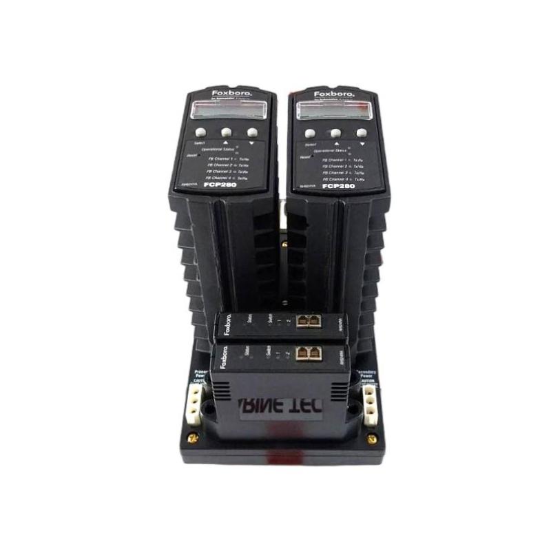
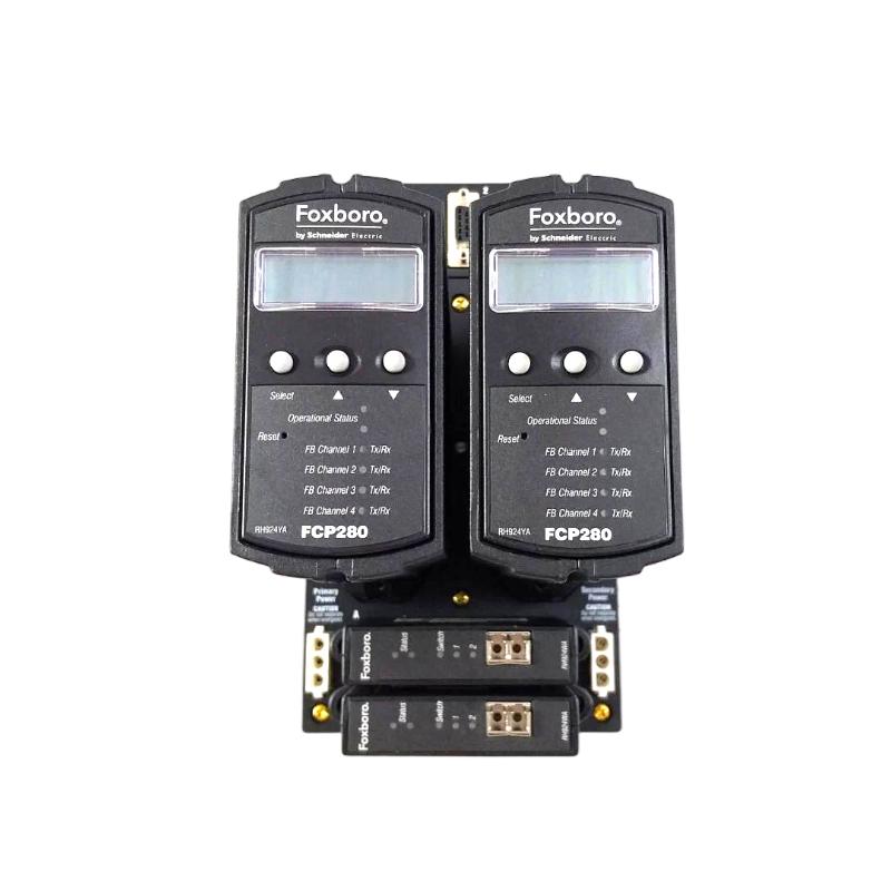
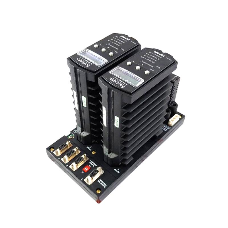
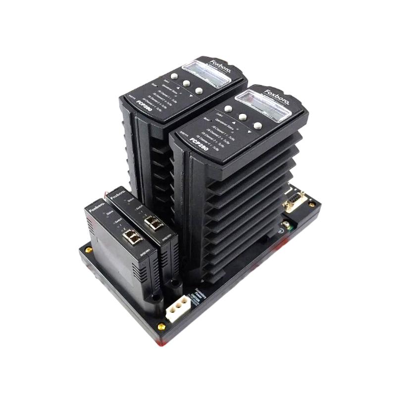
- Foxboro
- FCP280 RH924WA
- Fiber Optic Network Adapter
- USA
- 130 x 25 x 100 mm
- 0.4 kg
- Xiamen, China
- New & In Stock
- T/T, PayPal, Western Union
- 1 Year
- 1-3 Working Days
- DHL, UPS, TNT, FedEx and EMS.
- 24-Hour Service
- COO
- 60
Our advantage

Global Logistics
We have a 10-year logistics and express cooperation agreement, so our products can be shipped to any place in the world.

Brand new and original
Our products are imported in bulk from the place of origin. Because of the cooperative relationship, our products are all original and 100% new.

24-hour service
We provide 7*24 hours service to our customers. We will be there whenever you need us.

Price advantage
All our products are priced very favorably because we have our own warehouse and supply.
| Company Information | |||
| [email protected] | |||
| Mobile | +8615980777398 | ||
| +8615980777398 | |||
| 15980777398 |
Product Overview
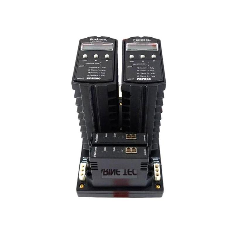
The Foxboro FCP280 RH924WA Fiber Optic Network Adapter is a dedicated communication adapter designed for the FCP280 Field Control Processor. Its primary function is to provide a fiber-optic interface between the FCP280 controller and the Foxboro DCS control network.
The RH924WA is installed on the FCP280 baseplate and forms part of the controller’s external communication architecture. In a redundant FCP280 arrangement, fiber-optic adapters can provide independent network paths between the controller assembly and the control-network switches.
Unlike the FCP280 processor, the RH924WA does not execute control logic. Its role is communication: it converts the controller-side network interface into the required fiber-optic connection and provides a robust communication path suitable for industrial DCS installations.
The product information supplied for this model specifies:
- Manufacturer: Foxboro
- Model: RH924WA
- Product Type: Fiber Optic Network Adapter
- Associated Controller: FCP280
- Dimensions: 130 × 25 × 100 mm
- Weight: 0.4 kg
The RH924WA is particularly useful where optical isolation, longer communication distances, reduced susceptibility to electromagnetic interference, and redundant control-network connections are required.
Technical Specifications
| Parameter | Specification |
|---|---|
| Manufacturer | Foxboro |
| Model | RH924WA |
| Associated Controller | FCP280 |
| Product Type | Fiber Optic Network Adapter |
| Communication Medium | Fiber Optic |
| Application | FCP280 Control Network |
| Mounting | FCP280 Baseplate |
| Network Architecture | Control Network / Mesh Architecture |
| Redundant Network Operation | Supported |
| Power Source | FCP280 Baseplate |
| Typical Fiber | Multimode Fiber |
| Communication Speed | 100 Mbps Ethernet architecture |
| Dimensions | 130 × 25 × 100 mm |
| Weight | 0.4 kg |
| Installation Environment | Industrial Automation / DCS Cabinet |
The RH924WA is designed specifically as the fiber-optic network interface for FCP280 installations rather than as a general-purpose Ethernet fiber converter.
Function and Working Principle
The RH924WA provides the optical communication path between the FCP280 and the DCS control network.
A simplified communication structure is:
FCP280
↓
RH924WA Fiber Optic Network Adapter
↓
Fiber-Optic Cable
↓
Ethernet / Control Network Switch
↓
Foxboro DCS Control Network
↓
Operator / Engineering / Control Stations
The adapter allows the controller to communicate with the control network using fiber-optic transmission.
In a redundant configuration, two network adapters can be associated with separate network switches.
A simplified redundant arrangement is:
FCP280 Primary
→ RH924WA #1
→ Network Switch A
FCP280 Primary
→ RH924WA #2
→ Network Switch B
This architecture provides network-path redundancy.
If one network switch, cable, or communication path becomes unavailable, the other path can continue providing communication depending on the overall DCS configuration.
Why Fiber Optic Communication Is Used
Fiber-optic communication provides several important advantages in industrial environments.
Electrical Isolation
Fiber does not conduct electrical current between the controller and network equipment. This helps reduce problems associated with electrical potential differences.
EMI Resistance
Fiber-optic communication is highly resistant to electromagnetic interference.
This is particularly valuable around:
- Variable-frequency drives
- Large motors
- Transformers
- High-current power cables
- Switching equipment
- Welding equipment
Long Communication Distances
Fiber can support longer communication paths than conventional copper Ethernet in appropriate network architectures.
Improved Industrial Network Reliability
Fiber communication can help separate sensitive control-network communication from electrically noisy environments.
RH924WA in a Redundant FCP280 System
The RH924WA becomes particularly important in a fault-tolerant FCP280 installation.
A typical arrangement can be represented as:
FCP280 A
↙ ↘
RH924WA A1 RH924WA A2
↓ ↓
Switch A Switch B
The FCP280 baseplate manages the communication paths so that the controller can communicate through the available network infrastructure.
This architecture can reduce the impact of:
- Fiber cable failure
- Network switch failure
- Network port failure
- Adapter failure
- Network-path interruption
Redundancy should always be verified at the complete system level rather than by looking at the RH924WA alone.
Installation Guide
1. Verify the Adapter
Before installation, confirm:
Foxboro FCP280 RH924WA
Check the model carefully because the FCP280 system can use different network adapter types.
The RH924WA is the fiber-optic network adapter. A copper network adapter is a different component and should not be substituted simply because it provides an Ethernet interface.
2. Inspect the RH924WA
Before installing the adapter, inspect:
- Housing
- Mounting hardware
- Electrical connector
- Fiber-optic connector
- Optical interface
- Protective covers
- Mechanical locking components
Check for:
- Cracks
- Scratches affecting the connector
- Contamination
- Bent contacts
- Broken mounting parts
- Signs of impact
Fiber-optic connectors require particular attention because dust or contamination can significantly reduce optical performance.
3. Prepare the FCP280 Baseplate
The RH924WA is installed on the FCP280 baseplate.
Before installation:
- Confirm the correct baseplate.
- Disconnect power if required by the maintenance procedure.
- Inspect the adapter position.
- Check the connector.
- Make sure the mounting location is clean.
- Verify that there is no mechanical obstruction.
Do not install the adapter into a damaged baseplate.
4. Install the RH924WA
Align the adapter with the designated mounting position.
Carefully insert the RH924WA.
Verify:
- Correct orientation
- Correct alignment
- Complete seating
- Secure mechanical attachment
- Proper connector engagement
Do not force the module.
If the adapter does not seat normally, remove it and check alignment rather than applying excessive force.
5. Connect Power Through the Baseplate
The RH924WA receives its required operating power through the FCP280 baseplate architecture.
Before energizing:
- Verify the controller power supply.
- Check baseplate connections.
- Confirm power polarity.
- Inspect wiring.
- Check that no short circuit exists.
A network-adapter communication fault can sometimes originate from an unstable controller power supply.
6. Prepare the Fiber-Optic Cable
Before connecting the fiber cable, inspect:
- Connector
- Ferrule
- Fiber end face
- Protective cap
- Cable jacket
- Bend radius
Keep connector protective caps in place whenever the optical connector is not connected.
Never touch the optical end face with bare fingers.
7. Connect the Fiber
Connect the fiber cable carefully.
Verify that:
- The connector is fully seated.
- The locking mechanism is engaged.
- The cable is not sharply bent.
- The cable is not under tension.
- The cable is routed away from mechanical damage.
Fiber-optic cables should not be pulled, crushed, or sharply bent during installation.
8. Connect the Network Switch
Connect the opposite end of the fiber cable to the designated control-network switch.
Verify:
- Correct switch
- Correct port
- Correct fiber type
- Correct connector
- Correct network configuration
For redundant systems, each RH924WA communication path should be connected according to the approved network architecture.
9. Verify the Network Path
After installation, verify:
FCP280 → RH924WA → Fiber → Network Switch
The complete path should be inspected before commissioning.
Commissioning Procedure
Step 1: Energize the FCP280
Apply the required system power.
Step 2: Check RH924WA Status
Verify that the adapter is correctly recognized by the controller/network architecture.
Step 3: Check Fiber Link
Inspect the network-switch port and communication status.
Step 4: Check Controller Communication
Verify communication between the FCP280 and the control network.
Step 5: Check Network Redundancy
For redundant systems, verify both communication paths.
Step 6: Verify DCS Communication
Confirm that the controller is visible to the appropriate DCS engineering and operator environment.
Step 7: Check Controller Data
Verify:
- Controller status
- Process data
- Alarms
- Communication diagnostics
- Network status
Step 8: Perform Failure Testing
Where permitted by the commissioning procedure, test the redundant communication path by temporarily removing one network path and confirming that communication remains available through the alternate path.
Troubleshooting Guide
Problem 1: RH924WA Has No Communication
Possible causes include:
- Adapter not properly seated
- Fiber cable disconnected
- Incorrect network port
- Contaminated fiber connector
- Damaged fiber cable
- Network switch problem
- Controller power problem
- Network configuration problem
Recommended Procedure
- Check controller power.
- Inspect the RH924WA.
- Verify adapter seating.
- Check fiber connectors.
- Check the fiber cable.
- Inspect switch-port status.
- Check network configuration.
- Review FCP280 communication diagnostics.
Problem 2: Fiber Link Is Down
If the network switch reports no optical link:
Check the Fiber First
Inspect both ends of the fiber cable.
Check:
- Connector seating
- Fiber type
- Cable condition
- Connector cleanliness
- Correct switch port
Check the Adapter
Verify that the RH924WA is properly installed.
Check the Switch
Confirm that the corresponding optical port is active and correctly configured.
Problem 3: Intermittent Fiber Communication
Intermittent communication can be caused by:
- Loose connector
- Contaminated optical interface
- Damaged fiber
- Excessive cable bending
- Excessive mechanical stress
- Poor network connection
- Adapter hardware fault
Inspect the physical fiber path carefully.
A fiber cable can appear intact externally while still having optical-performance problems.
Problem 4: Communication Works After Restart but Later Fails
If the communication link returns after restarting the controller, investigate:
- Power stability
- Fiber connection
- Adapter temperature
- Network switch
- Network configuration
- Intermittent connector problems
Do not assume that restarting the controller has corrected the underlying problem.
Problem 5: One Redundant Network Path Is Offline
If one RH924WA path operates normally but the second path is unavailable:
- Check the second adapter.
- Check its fiber cable.
- Check the second switch.
- Check the switch port.
- Inspect connectors.
- Compare diagnostic information between both paths.
This fault pattern is useful because the working path provides a reference for comparison.
Problem 6: Both Network Paths Fail
If both redundant paths fail simultaneously, investigate common infrastructure first.
Potential causes include:
- FCP280 power failure
- Baseplate problem
- Controller failure
- Network configuration problem
- Common network equipment failure
- Incorrect maintenance procedure
If both fiber paths fail at exactly the same time, a common upstream problem is generally more likely than two independent fiber failures.
Problem 7: High Communication Error Rate
A high error rate can result from:
- Dirty optical connector
- Damaged fiber
- Excessive fiber bending
- Poor connection
- Optical signal degradation
- Network switch problem
- Incorrect network configuration
Check the physical optical path before replacing the RH924WA.
Problem 8: RH924WA Is Replaced but the Fault Remains
If replacing the adapter does not correct the problem, inspect:
- Fiber cable
- Network switch
- Network port
- FCP280 baseplate
- Controller
- Power supply
- Network configuration
Replacing the adapter without identifying the fault location can result in unnecessary component replacement.
Fiber-Optic Maintenance
Fiber-optic communication requires careful maintenance.
Connector Cleaning
Fiber connectors should be kept clean.
Contamination can cause:
- Increased optical loss
- Link instability
- Communication errors
- Reduced communication reliability
Cable Routing
Avoid:
- Sharp bends
- Crushing
- Excessive tension
- Repeated flexing
- Heavy objects on fiber cables
Protective Caps
Always use protective caps when optical connectors are disconnected.
Maintenance Checklist
| Item | Inspection |
|---|---|
| RH924WA | Physical condition |
| Adapter Connector | Clean and undamaged |
| Baseplate | Secure connection |
| Fiber Connector | Clean and fully seated |
| Fiber Cable | No damage |
| Cable Routing | No sharp bends |
| Network Switch | Port operational |
| Link Status | Normal |
| Power | Stable |
| Redundant Path | Available |
| Diagnostics | No recurring faults |
Industrial Applications
Oil and Gas
The RH924WA can support fiber-based FCP280 control-network communication in:
- Refineries
- Gas-processing facilities
- Compressor stations
- Pipeline facilities
- Offshore process systems
Fiber is particularly useful where long cable runs and high electrical noise are present.
Chemical Plants
Potential applications include:
- Reactor control
- Batch processing
- Pressure control
- Temperature control
- Flow control
- Utility systems
Fiber communication can help maintain reliable network connectivity between control cabinets and network switches.
Power Generation
Applications can include:
- Turbine auxiliary systems
- Cooling systems
- Water systems
- Fuel systems
- Boiler auxiliary systems
- Electrical utility control
Fiber provides electrical isolation between network components where appropriate.
Water and Wastewater
The RH924WA can be used in distributed control architectures supporting:
- Pump stations
- Water-treatment plants
- Filtration systems
- Chemical dosing
- Reservoir control
- Wastewater processing
Compatible System Components
| Component | Function |
|---|---|
| RH924WA | FCP280 Fiber Optic Network Adapter |
| FCP280 | Field Control Processor |
| RH924YL | Horizontal FCP280 Baseplate |
| RH924YF | Vertical FCP280 Baseplate |
| RH924UQ | FCP280 Copper Network Adapter |
| Fieldbus Modules | Distributed I/O |
| Fiber-Optic Cable | Network Communication |
| Control Network Switch | Ethernet Network |
| DC Power Supply | System Power |
Component compatibility should be verified against the complete FCP280 system architecture before replacement.
RH924WA vs RH924UQ
| Feature | RH924WA | RH924UQ |
|---|---|---|
| Product Type | Fiber Optic Network Adapter | Copper Network Adapter |
| Associated Controller | FCP280 | FCP280 |
| Communication Medium | Fiber Optic | Copper Ethernet |
| Electrical Isolation | High | Limited by copper architecture |
| EMI Immunity | Excellent | Lower than fiber |
| Long-Distance Applications | Suitable | More limited |
| Typical Use | Industrial control networks | Copper Ethernet networks |
| Redundant Configuration | Supported | Supported |
| Primary Advantage | Optical communication | Simple copper connectivity |
The correct choice depends on the existing network architecture, cable infrastructure, distance, electrical environment, and redundancy requirements.
RH924WA vs RH924YF
These two components serve different purposes.
| Component | Function |
|---|---|
| RH924WA | Fiber-optic network adapter |
| RH924YF | Vertical FCP280 baseplate |
RH924WA is a communication adapter, while RH924YF is a mounting/interconnection baseplate.
They are therefore not interchangeable.
RH924WA vs RH924YL
| Component | Function |
|---|---|
| RH924WA | Fiber-optic network interface |
| RH924YL | Horizontal FCP280 mounting base |
The RH924WA is installed as part of the FCP280 network interface arrangement, while RH924YL provides the physical mounting platform.
Both can be part of the same FCP280 installation.
Key Advantages
- Designed for FCP280 network integration
- Fiber-optic communication
- Suitable for industrial DCS applications
- Provides optical isolation
- High resistance to electromagnetic interference
- Supports redundant network architectures
- Suitable for control-network communication
- Compatible with FCP280 baseplate architecture
- Suitable for demanding industrial environments
- Supports structured fiber network installations
- Useful for long communication paths
- Reduces dependence on copper communication wiring
- Suitable for critical-process applications
- Supplied dimensions: 130 × 25 × 100 mm
- Supplied weight: 0.4 kg
Technical FAQs
What is the Foxboro FCP280 RH924WA?
The RH924WA is a fiber-optic network adapter designed for the Foxboro FCP280 Field Control Processor.
What is the primary function of RH924WA?
Its primary function is to provide the fiber-optic communication interface between the FCP280 and the Foxboro DCS control network.
Is RH924WA a controller?
No. RH924WA is a network adapter. Control logic and process-control functions are performed by the FCP280.
Where is RH924WA installed?
The adapter is installed on the FCP280 baseplate as part of the controller’s network interface.
What are the dimensions of RH924WA?
The supplied dimensions are:
130 × 25 × 100 mm
What is the weight?
The supplied weight is:
0.4 kg
Can RH924WA be used in a redundant FCP280 system?
Yes. Fiber-optic network adapters can be used as part of redundant FCP280 control-network architectures.
What is the difference between RH924WA and RH924UQ?
RH924WA provides a fiber-optic network interface, while RH924UQ is intended for copper Ethernet network connectivity.
Why use fiber instead of copper?
Fiber provides strong immunity to electromagnetic interference and electrical isolation, making it useful in industrial environments with high levels of electrical noise.
What should be checked when the RH924WA loses communication?
Check:
- FCP280 power.
- Adapter seating.
- Fiber connectors.
- Fiber cable.
- Network switch.
- Switch port.
- Network configuration.
- Controller diagnostics.
Can a dirty fiber connector cause communication problems?
Yes. Contamination at an optical connector can increase optical loss and cause unstable or failed communication.
What causes intermittent fiber communication?
Common possibilities include:
- Contaminated connectors
- Damaged fiber
- Loose connections
- Excessive cable bending
- Mechanical stress
- Network-switch problems
- Adapter problems
Should the RH924WA be replaced immediately if communication fails?
No. First determine whether the fault is located in the adapter, fiber cable, network switch, baseplate, controller, power supply, or network configuration.
Can RH924WA be used with the RH924YL?
Yes. RH924YL is an FCP280 horizontal mounting base, while RH924WA is the fiber-optic network adapter. They serve different functions and can form part of the same controller installation.
Conclusion
The Foxboro FCP280 RH924WA Fiber Optic Network Adapter is a specialized communication component for FCP280-based distributed control systems. It provides the fiber-optic interface required to connect the FCP280 controller to the industrial control network.
Its fiber-based architecture makes it particularly valuable in environments where electromagnetic interference, electrical isolation, communication distance, and network redundancy are important considerations.
With the supplied dimensions of 130 × 25 × 100 mm and weight of 0.4 kg, the RH924WA provides a compact communication interface that can be integrated into an FCP280 baseplate installation.
For installation, engineers should pay close attention to adapter seating, fiber connector cleanliness, cable routing, network-switch connections, and redundant communication paths. During troubleshooting, the fiber cable and optical connectors should be checked before assuming that the RH924WA itself has failed.
In a redundant FCP280 architecture, the RH924WA can contribute to a resilient network design by providing separate optical communication paths. Proper system configuration, correct fiber installation, and regular inspection are essential for maintaining reliable control-network communication.