

ProductPRODUCT
Featured products
Contact Us
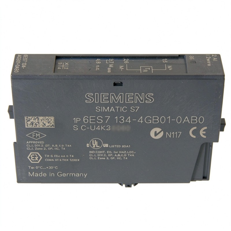
- Siemens
- 6ES7134-4GB01-0AB0
- Analog Input Module
- Germany
- 15 × 81 × 52 mm
- 0.044 kg
- Xiamen, China
- New & In Stock
- T/T, PayPal, Western Union
- 1 Year
- 1-3 Working Days
- DHL, UPS, TNT, FedEx and EMS.
- 24-Hour Service
- COO
- 29
Our advantage

Global Logistics
We have a 10-year logistics and express cooperation agreement, so our products can be shipped to any place in the world.

Brand new and original
Our products are imported in bulk from the place of origin. Because of the cooperative relationship, our products are all original and 100% new.

24-hour service
We provide 7*24 hours service to our customers. We will be there whenever you need us.

Price advantage
All our products are priced very favorably because we have our own warehouse and supply.
| Company Information | |||
| [email protected] | |||
| Mobile | +8615980777398 | ||
| +8615980777398 | |||
| 15980777398 |
Product Overview
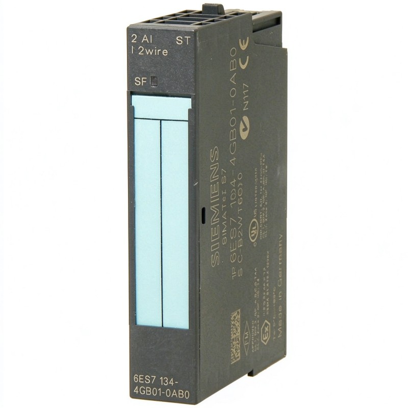
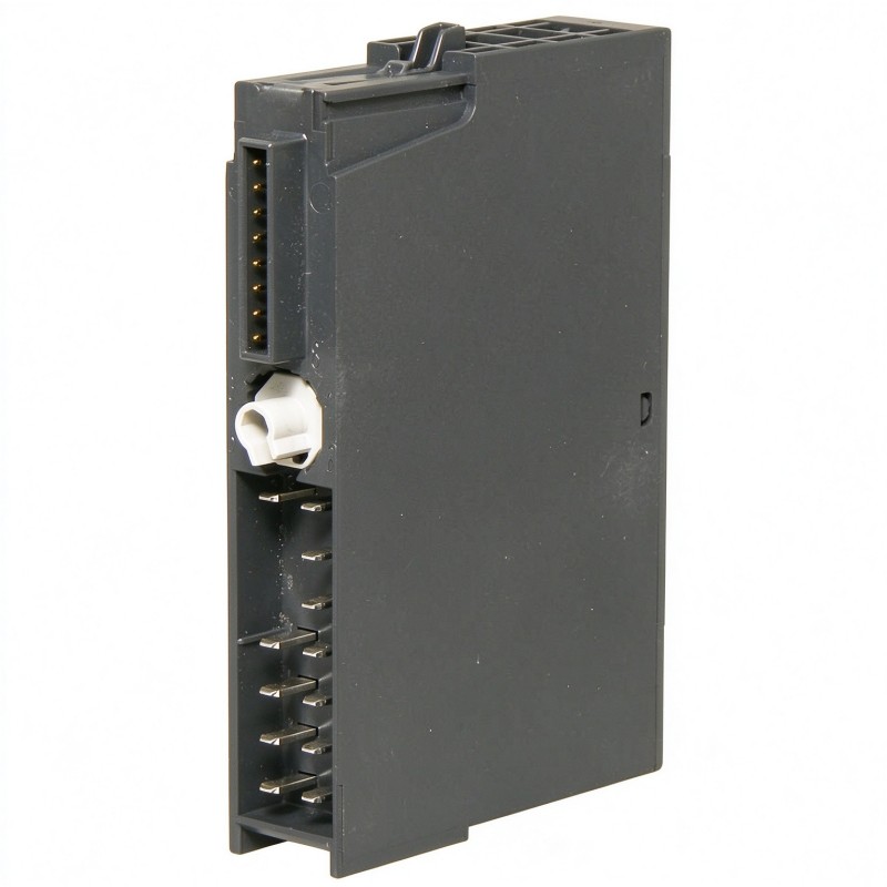
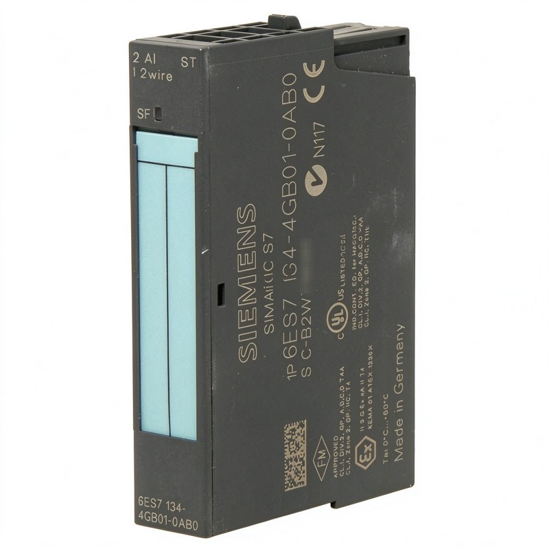
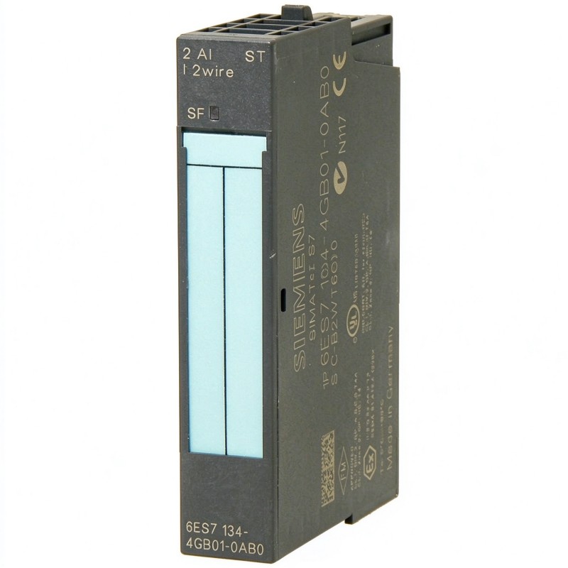
The Siemens 6ES7134-4GB01-0AB0 SIMATIC ET 200S Analog Input Module is a two-channel analog current input module used to acquire 4–20 mA signals from industrial field instruments. It belongs to the SIMATIC ET 200S distributed I/O family and provides the interface between two-wire transmitters and a higher-level PLC.
Unlike voltage-input modules in the same product family, the 6ES7134-4GB01-0AB0 is specifically configured for current measurement. It supports two analog input channels, each accepting a 4–20 mA signal through a 50 Ω input resistance. Its 13-bit resolution allows the controller to distinguish changes in the measured current and convert them into process values.
This configuration is commonly used with pressure transmitters, level instruments, flow meters, and other two-wire measuring devices. For example, a pressure transmitter installed on an industrial pipeline can send a 4–20 mA signal to one channel, while the second channel collects a measurement from another instrument. The ET 200S station transfers both measurement values to the PLC for monitoring, alarm handling, and process control.
The module uses an integrating measurement principle. Its conversion time is approximately 65 ms per channel, making it suitable for conventional process instrumentation where measurement stability and signal acquisition are more important than high-speed sampling.
A practical feature of this version is its ability to supply power to connected two-wire transducers through the load voltage provided by the ET 200S power module. This simplifies the wiring arrangement for compatible field instruments and reduces the need for separate transmitter power connections.
The module also supports configurable measured-value smoothing in four stages. This is useful when analog signals fluctuate because of electrical interference or process variations. The SF LED provides group fault indication, while diagnostic functions help identify conditions such as wire breaks and overrange or underrange signals.
With a width of only 15 mm, the 6ES7134-4GB01-0AB0 fits into compact ET 200S distributed I/O stations. It is particularly suitable for control cabinets containing multiple current-loop instruments where installation space and organized field wiring are important considerations.
Technical Specifications
| Parameter | Specification |
|---|---|
| Manufacturer | Siemens |
| Model | 6ES7134-4GB01-0AB0 |
| Product Type | Analog Input Module |
| Product Family | SIMATIC ET 200S |
| Module Designation | 2AI I 2WIRE ST |
| Number of Analog Inputs | 2 |
| Input Signal Type | Current |
| Input Range | 4–20 mA |
| Input Resistance | 50 Ω |
| Resolution | 13 bit |
| Supported Transmitter Type | 2-Wire Transducer |
| Conversion Time | 65 ms per channel |
| Integration Time | 16.7 / 20 ms |
| Measurement Principle | Integrating |
| Measured Value Smoothing | 4 Configurable Stages |
| Supply Voltage | 24 V DC (from power module) |
| Power Consumption | 0.6 W |
| Maximum Shielded Cable Length | 200 m |
| Isochronous Operation | Not Supported |
| Diagnostic Indication | Red SF LED |
| Protection Rating | IP20 |
| Dimensions | 15 × 81 × 52 mm |
| Weight | 0.044 kg |
Product Features
- Two Current Input Channels: Acquires two independent 4–20 mA measurement signals within one electronic module.
- Two-Wire Transmitter Support: Supplies connected compatible transmitters through the ET 200S load voltage arrangement.
- 13-Bit Resolution: Converts incoming current signals into digital measurement values.
- 50 Ω Input Resistance: Provides the specified electrical input resistance for current measurement.
- Integrating Measurement: Uses an integration-based conversion process with selectable integration times.
- Configurable Signal Smoothing: Offers four filtering stages to handle fluctuating analog measurements.
- Wire-Break Diagnostics: Helps identify interrupted field signal connections.
- Overrange and Underrange Monitoring: Supports detection of signals outside the configured measurement range.
- Group Fault Indication: Uses a red SF LED to indicate module diagnostic conditions.
- Compact 15 mm Installation: Fits narrow ET 200S distributed I/O configurations.
Working Principle
The 6ES7134-4GB01-0AB0 measures the electrical current supplied by connected field transmitters and converts that current into digital values for the SIMATIC controller.
Its signal acquisition process follows this general arrangement:
Two-Wire Transmitter → ET 200S Terminal Module → 6ES7134-4GB01-0AB0 → Analog-to-Digital Conversion → Backplane Bus → PLC
In a typical installation, a two-wire transmitter receives its operating power through the field wiring and produces a current signal proportional to the measured process variable. The signal enters one of the module’s two analog input channels.
The module measures the current within the 4–20 mA range using its 50 Ω input resistance. An integrating conversion process evaluates the signal over a defined period before generating the corresponding digital measurement value.
The module supports integration times of 16.7 ms and 20 ms, corresponding to different interference frequency suppression settings. This helps reduce the influence of common electrical disturbances on the acquired measurement.
After conversion, the digital value is transferred through the ET 200S backplane bus to the interface module and then to the higher-level PLC. The controller can scale the value into engineering units and use it in control programs.
For example, consider a water treatment system with two pressure transmitters installed at different points in a filtration line. Each transmitter sends a 4–20 mA signal to a separate input channel. The module acquires both signals, allowing the PLC to compare upstream and downstream pressure and identify abnormal pressure differences across the filter.
The configurable smoothing function is particularly useful when measurements fluctuate. Four filtering stages are available, allowing the signal response to be adjusted according to the application. Higher smoothing can reduce short-term fluctuations, although it also increases the response time to actual process changes.
Diagnostic functions provide additional information when signal wiring or measurement conditions become abnormal. A wire break, for example, can interrupt the expected current signal and trigger a diagnostic response when the corresponding monitoring function is configured.
Role in the SIMATIC ET 200S Distributed I/O Architecture
The 6ES7134-4GB01-0AB0 serves as the current signal acquisition interface within an ET 200S distributed I/O station. It connects two-wire field instruments to the automation system and transfers their measurement values to the central controller.
A typical signal path follows this arrangement:
Two-Wire Field Transmitters → ET 200S Terminal Module → 6ES7134-4GB01-0AB0 → ET 200S Backplane Bus → Interface Module → SIMATIC PLC
| System Component | Function |
|---|---|
| Two-Wire Pressure Transmitter | Converts pipeline pressure into a 4–20 mA signal |
| Two-Wire Level Transmitter | Supplies current signals representing liquid level |
| ET 200S Terminal Module | Provides the electrical connection and mounting interface |
| 6ES7134-4GB01-0AB0 | Acquires two 4–20 mA current signals |
| ET 200S Backplane Bus | Transfers digital measurement data within the station |
| Interface Module | Connects the distributed I/O station to the automation network |
| 24 V DC Power Module | Supplies the required load voltage and supports transmitter power |
| SIMATIC PLC | Processes measurement values and executes control logic |
| Shielded Signal Cable | Carries analog signals while reducing electrical interference |
The two-wire transmitter arrangement is an important part of this module’s application. Unlike a voltage-input module, the 6ES7134-4GB01-0AB0 measures current-loop signals and supports the power requirements of compatible two-wire instruments through the ET 200S power arrangement.
The terminal module must be selected according to the required wiring configuration. Correct terminal assignment, polarity, and cable shielding are essential for maintaining accurate measurements.
The module also differs from the high-speed current-input versions in the ET 200S family. Its 65 ms conversion time per channel makes it appropriate for standard process monitoring rather than applications requiring rapid analog acquisition.
Industrial Applications
| Application | Typical Use |
|---|---|
| Water Treatment Plants | Acquiring 4–20 mA signals from pressure, level, and flow transmitters |
| Chemical Processing | Monitoring process variables through two-wire field instruments |
| Oil and Gas Facilities | Collecting current-loop measurements from pipeline instrumentation |
| Pumping Stations | Monitoring discharge pressure and fluid level |
| Pharmaceutical Manufacturing | Acquiring process measurements for automated monitoring |
| Food and Beverage Production | Connecting temperature, pressure, and level instrumentation |
| Power Generation | Monitoring auxiliary system pressure and operating conditions |
| Industrial Utilities | Collecting measurements from centralized instrumentation systems |
| Manufacturing Lines | Monitoring pressure and flow conditions in production equipment |
| Wastewater Treatment | Acquiring level and process measurements from field transmitters |
Installation and Maintenance
- Verify the Module Number: Confirm that 6ES7134-4GB01-0AB0 matches the intended ET 200S configuration and that two 4–20 mA input channels are required.
- Check Transmitter Compatibility: Verify that the connected instruments provide 4–20 mA outputs and that their electrical configuration is suitable for two-wire transmitter operation.
- Select the Correct Terminal Module: Confirm that the installed ET 200S terminal module supports the required terminal assignments and wiring arrangement.
- Isolate the Power Supply: Disconnect the relevant supply according to the site’s electrical safety and lockout procedures before installing or removing the module.
- Inspect the Mounting Position: Check the terminal module, contacts, and mounting area for contamination, corrosion, or mechanical damage.
- Install the Electronic Module: Position the 6ES7134-4GB01-0AB0 on the designated ET 200S terminal module and secure it according to the system installation instructions.
- Connect the Current Signals: Wire the two transmitter outputs to their assigned input channels. Observe the specified positive and negative terminal connections.
- Check Transmitter Power: Verify that the 24 V DC load voltage from the power module is available and that the connected transmitters operate within their electrical requirements.
- Configure Signal Processing: Set the required integration time and measured-value smoothing stage according to the characteristics of the connected instruments.
- Check Cable Shielding: Use appropriately shielded analog signal cables and maintain suitable separation from power wiring. The maximum specified shielded cable length is 200 m.
- Test Both Input Channels: Restore the supply and verify the measured values using known current references. Check the SF LED and review diagnostic information if the readings are abnormal.
- Record the Configuration: Document transmitter identification, channel assignments, input wiring, integration settings, and maintenance information for future troubleshooting.
Compatible System Components
| Component | Function |
|---|---|
| Siemens 6ES7134-4GB01-0AB0 | Two-channel standard analog current input module |
| Siemens 6ES7134-4FB01-0AB0 | Two-channel standard analog voltage input module |
| Siemens 6ES7134-4GB52-0AB0 | ET 200S high-speed analog current input module |
| Siemens 6ES7135-4GB01-0AB0 | ET 200S analog current output module |
| Siemens 6ES7151-1AA05-0AB0 | ET 200S interface module |
| Siemens 6ES7138-4CA01-0AA0 | ET 200S power module |
| ET 200S Terminal Module | Provides module mounting and field wiring connections |
| 24 V DC Power Supply | Supplies operating voltage to the distributed I/O station |
| Two-Wire Pressure Transmitters | Provide 4–20 mA pressure measurement signals |
| Two-Wire Level Transmitters | Supply current signals for level measurement |
| Shielded Instrumentation Cable | Carries current-loop signals while reducing electrical interference |
Recommended Related Models
| Model | Product Type | Typical Application |
|---|---|---|
| Siemens 6ES7134-4FB01-0AB0 | SIMATIC ET 200S Analog Input Module | Two-channel standard voltage signal acquisition |
| Siemens 6ES7134-4GB52-0AB0 | SIMATIC ET 200S Analog Input Module | High-speed current signal acquisition |
| Siemens 6ES7134-4FB52-0AB0 | SIMATIC ET 200S Analog Input Module | High-speed voltage signal acquisition |
| Siemens 6ES7135-4GB01-0AB0 | SIMATIC ET 200S Analog Output Module | Analog current signal output |
| Siemens 6ES7135-4FB01-0AB0 | SIMATIC ET 200S Analog Output Module | Analog voltage signal output |
| Siemens 6ES7151-1AA05-0AB0 | SIMATIC ET 200S Interface Module | Distributed I/O network communication |
Key Advantages
- Two independent 4–20 mA input channels.
- Supports compatible two-wire field transmitters.
- 13-bit analog measurement resolution.
- 50 Ω input resistance for current signal acquisition.
- Integrating measurement with selectable integration time.
- Four configurable measured-value smoothing stages.
- Wire-break and range monitoring diagnostics.
- Compact 15 mm ET 200S installation width.
- Integration with SIMATIC ET 200S distributed I/O stations.
Technical FAQs
Can the 6ES7134-4GB01-0AB0 power two-wire transmitters directly?
The module supports two-wire transducer operation and uses the 24 V DC load voltage supplied by the ET 200S power module. The available supply and transmitter wiring must be checked against the module’s electrical specifications and the requirements of the connected instruments.
What is the difference between the 6ES7134-4GB01-0AB0 and 6ES7134-4FB01-0AB0?
The 6ES7134-4GB01-0AB0 is a current-input module for 4–20 mA signals, while the 6ES7134-4FB01-0AB0 is a voltage-input module supporting ±10 V, ±5 V, and 1–5 V signals. The choice depends on the output type of the connected field transmitter.
How does the measured-value smoothing function affect the input signal?
The module provides four configurable smoothing stages. Increasing the smoothing level reduces short-term fluctuations in the acquired measurement, which can be useful in electrically noisy environments. However, stronger smoothing also delays the response to actual changes in the process variable. The setting should therefore reflect the required balance between signal stability and response time.
What happens if a 4–20 mA transmitter signal falls outside the normal measurement range?
The module supports overrange and underrange monitoring as well as diagnostic information for abnormal input conditions. The PLC can use the available diagnostic data to identify measurement values outside the configured range. The actual response should be handled through the controller’s diagnostic and fault-processing logic.