

ProductPRODUCT
Featured products
Contact Us
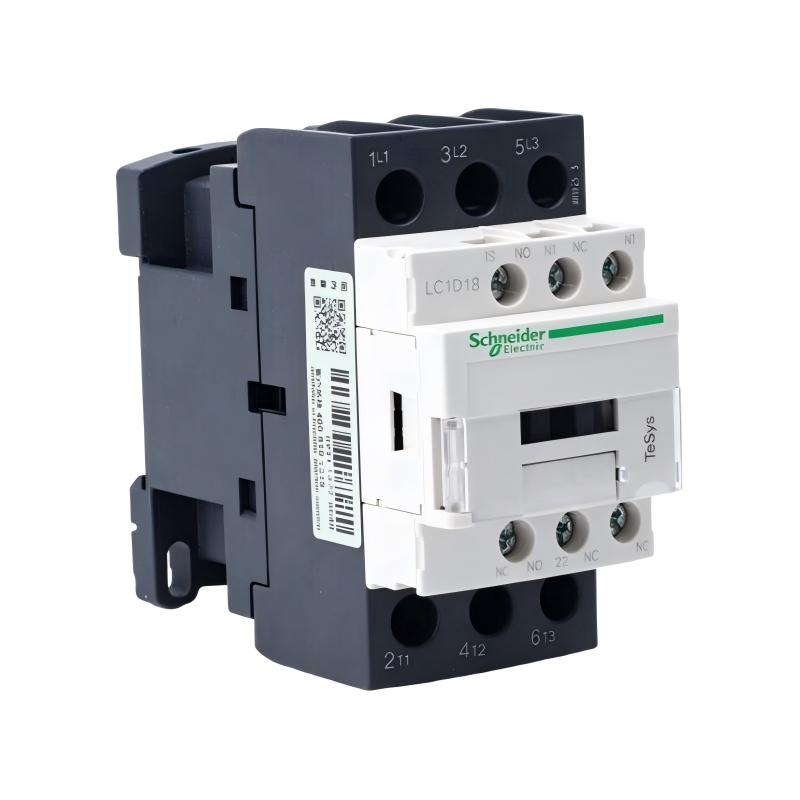
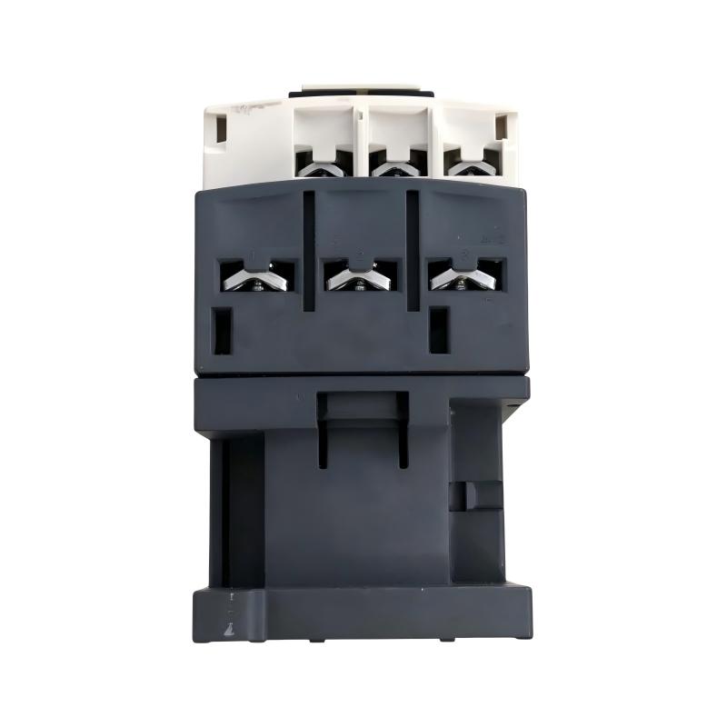
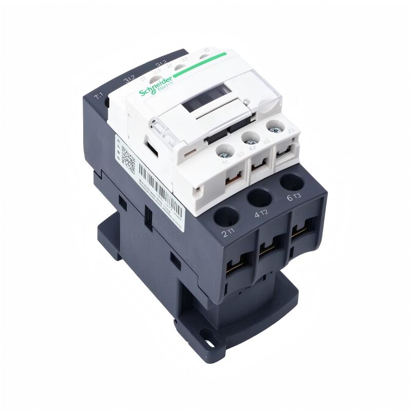
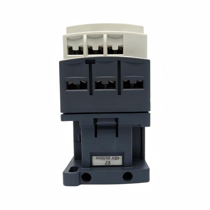
- Schneider
- LC1D18E7
- Contactor
- France
- 77 x 45 x 86 mm
- 0.33 kg
- Xiamen, China
- New & In Stock
- T/T, PayPal, Western Union
- 1 Year
- 1-3 Working Days
- DHL, UPS, TNT, FedEx and EMS.
- 24-Hour Service
- COO
- 2
Our advantage

Global Logistics
We have a 10-year logistics and express cooperation agreement, so our products can be shipped to any place in the world.

Brand new and original
Our products are imported in bulk from the place of origin. Because of the cooperative relationship, our products are all original and 100% new.

24-hour service
We provide 7*24 hours service to our customers. We will be there whenever you need us.

Price advantage
All our products are priced very favorably because we have our own warehouse and supply.
| Company Information | |||
| [email protected] | |||
| Mobile | +8615980777398 | ||
| +8615980777398 | |||
| 15980777398 |
Product Overview
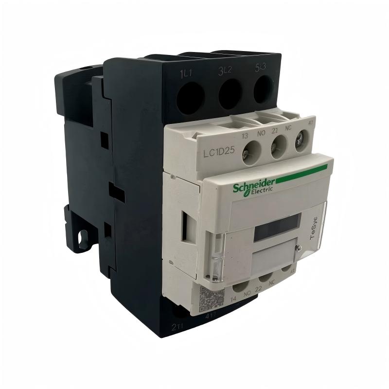
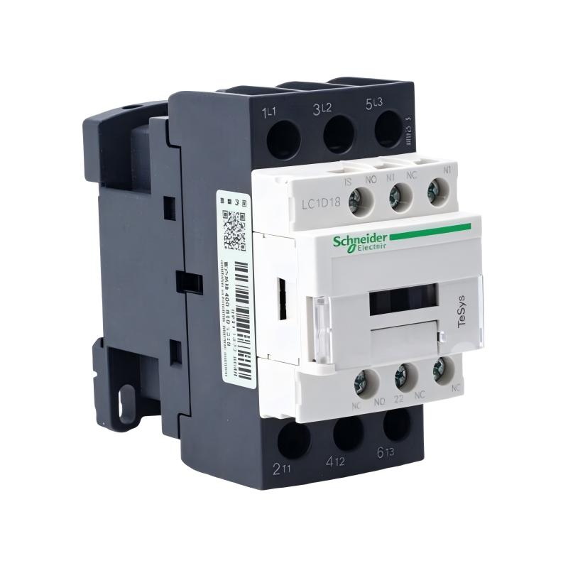
The Schneider Electric LC1D18E7 Contactor is an industrial electromagnetic switching device from the TeSys Deca (formerly TeSys D) product family. It is designed for controlling three-phase AC motors and switching resistive electrical loads in industrial control panels, machinery, and electrical distribution systems.
A contactor allows a control circuit to operate a power circuit remotely. When the coil receives its rated control voltage, an electromagnetic mechanism moves the internal contacts, connecting the main power circuit. When the coil is de-energized, the contacts return to their normal state and interrupt the connected circuit.
The LC1D18E7 features three normally open main power contacts and an AC-3 rated operational current of 18 A. It uses a 48 V AC coil operating at 50/60 Hz, making it suitable for control systems designed around this coil voltage. The device also incorporates one normally open and one normally closed auxiliary contact for control logic, status indication, and interlocking functions.
For motor-control applications, the contactor supports a rated motor power of 7.5 kW at 380–400 V AC under AC-3 conditions. Its AC-1 thermal current rating is 32 A, while the AC-3 operational current rating is 18 A. These ratings describe different utilization conditions and should not be treated as interchangeable.
The LC1D18E7 is commonly used in motor starters, pump control panels, fan systems, conveyor equipment, and industrial automation cabinets. Its compact construction and standard mounting arrangements make it suitable for integration into a wide range of electrical control assemblies.
Technical Specifications
| Parameter | Specification |
|---|---|
| Brand | Schneider Electric |
| Product Series | TeSys Deca / TeSys D |
| Model | LC1D18E7 |
| Product Type | Electromagnetic Contactor |
| Device Short Name | LC1D |
| Main Contact Configuration | 3P, 3 NO |
| AC-3 Rated Operational Current | 18 A |
| AC-1 Rated Current | 32 A |
| Coil Voltage | 48 V AC |
| Coil Frequency | 50/60 Hz |
| Auxiliary Contacts | 1 NO + 1 NC |
| Rated Operational Voltage | Up to 690 V AC for power circuit |
| AC-3 Motor Power at 380–400 V | 7.5 kW |
| AC-3 Motor Power at 415–440 V | 9 kW |
| AC-3 Motor Power at 500 V | 10 kW |
| AC-3 Motor Power at 660–690 V | 10 kW |
| Mounting | DIN rail or panel mounting, subject to installation configuration |
| Terminal Type | Screw clamp terminals |
| Rated Impulse Withstand Voltage | 6 kV |
| Dimensions | 77 × 45 × 86 mm |
| Weight | 0.33 kg |
| Typical Applications | Motor control, resistive load switching, industrial automation |
Electrical ratings depend on utilization category, operating voltage, ambient temperature, and installation conditions. Always check the manufacturer’s technical documentation when selecting the contactor for a specific load.
Function and Working Principle
The LC1D18E7 uses an electromagnetic operating mechanism to switch electrical circuits. Its operation involves the coil, magnetic core, moving armature, main contacts, and auxiliary contacts.
1. Electromagnetic Coil Operation
The contactor’s coil is rated for 48 V AC at 50/60 Hz. When the correct control voltage is applied to the coil terminals, an electromagnetic field is generated.
This magnetic field attracts the moving armature toward the fixed magnetic core. The mechanical movement operates the contact system, changing the state of the main and auxiliary contacts.
When the coil supply is removed, the electromagnetic force disappears and the return mechanism restores the contacts to their normal positions.
2. Main Power Switching
The LC1D18E7 contains three normally open main contacts. These contacts are used to connect or disconnect the three phases of a compatible power circuit.
When the coil is energized, all three main contacts close, allowing current to flow to the connected load. When the coil is de-energized, the contacts open and interrupt the power circuit.
This arrangement is widely used in non-reversing motor starters and other three-phase switching applications.
3. Auxiliary Contact Operation
The contactor includes one normally open and one normally closed auxiliary contact.
These contacts are generally used in control circuits rather than as the primary power contacts. They can provide feedback about the contactor’s operating state, maintain a control sequence, or support electrical interlocking.
For example, an auxiliary contact may be connected to a PLC input to indicate whether the contactor has been commanded into its energized state. The actual feedback arrangement must be designed according to the control system requirements.
4. AC-3 Motor Switching
The AC-3 utilization category applies to starting squirrel-cage motors and switching them off while running. Motor starting and stopping can create electrical conditions that differ significantly from resistive loads.
The LC1D18E7 has an AC-3 rated current of 18 A. This rating is particularly relevant when selecting the contactor for motor-control applications.
The contactor should be selected according to motor current, supply voltage, starting conditions, duty cycle, and the manufacturer’s utilization-category ratings.
5. AC-1 Resistive Load Switching
For resistive loads, the contactor has an AC-1 current rating of 32 A. AC-1 applications generally involve non-inductive or slightly inductive loads.
The higher AC-1 rating does not mean the contactor can switch a motor at 32 A under AC-3 conditions. Motor applications must be evaluated using the appropriate motor utilization category.
Role in Industrial Control Systems
The LC1D18E7 is commonly installed as part of an industrial motor starter or electrical control assembly. It provides the switching function between a power source and a connected electrical load.
PLC-Based Motor Control
A programmable logic controller can control the contactor through an appropriately rated control circuit. The PLC processes operating commands and interlock conditions before activating the contactor coil.
Because the LC1D18E7 uses a 48 V AC coil, the control circuit must provide a compatible voltage and sufficient current capacity. A PLC output should not be connected directly to the coil unless its electrical rating and switching characteristics are suitable. An interposing relay or interface device may be required.
Motor Starter Circuits
In a conventional motor starter, the contactor works together with short-circuit protection and motor overload protection.
The contactor performs the routine switching operation, while the protective devices address electrical faults and overload conditions. These functions are complementary and should be coordinated according to the motor and installation requirements.
HMI and Operator Interface
An HMI can provide operators with start, stop, and status functions through the PLC or a dedicated control circuit.
The LC1D18E7 itself does not provide a digital display or programmable interface. Its role is to execute the electrical switching command received from the control system.
Auxiliary Feedback and Interlocking
The built-in 1NO + 1NC auxiliary contacts can support control sequences and electrical interlocking.
For example, an auxiliary contact may be used to prevent two incompatible contactors from being energized simultaneously. Another contact may provide an operating-state signal to a PLC or indicator circuit.
The control designer should confirm the required contact logic and electrical ratings before wiring these functions.
Industrial Applications
The LC1D18E7 can be used in a range of industrial electrical systems where its 18 A AC-3 rating and 48 V AC coil configuration meet the application requirements.
1. Industrial Pump Control
Pumping systems frequently use contactors to start and stop electric motors. The LC1D18E7 can serve as the switching component in a suitable motor starter.
Applications include auxiliary water pumps, industrial circulation systems, and compatible process pumps. The motor’s rated current and starting characteristics must remain within the contactor’s applicable ratings.
2. Fan and Ventilation Systems
Industrial ventilation equipment often requires reliable motor switching. The contactor can be used to control compatible fan motors in HVAC systems, production facilities, and equipment rooms.
Where several fans operate in sequence, auxiliary contacts can help provide feedback or support interlocking logic.
3. Conveyor Systems
Conveyors are widely used in manufacturing, packaging, and material-handling operations. The LC1D18E7 can control a compatible conveyor motor through a conventional contactor-based starter.
PLC logic can coordinate the contactor with sensors, emergency-stop circuits, and other machine components. The overall control system must include appropriate safety and overload protection.
4. Packaging Machinery
Packaging equipment may contain motors for feeding, transferring, sealing, and handling products. A contactor can provide the electrical switching function for compatible motor circuits.
Its auxiliary contacts can be incorporated into machine-control sequences to help coordinate equipment operation.
5. Industrial Electrical Panels
The compact dimensions of the LC1D18E7 make it suitable for installation in industrial control panels where space and wiring organization are important.
It can be used in motor starter assemblies, auxiliary equipment control circuits, and general industrial switching applications, provided the electrical ratings are appropriate.
6. Resistive Heating and Auxiliary Loads
The contactor can also be considered for compatible resistive loads within its AC-1 rating. Examples may include certain heating circuits and auxiliary electrical loads.
The load current, switching frequency, ambient temperature, and protection arrangement should be evaluated before installation.
Installation and System Integration
Correct installation is essential for safe switching, reliable operation, and the expected service life of the contactor.
1. Verify the Coil Voltage
Before connecting the control circuit, confirm that the coil supply is 48 V AC at 50/60 Hz.
Using an incorrect coil voltage may prevent reliable operation or damage the coil. The coil voltage must be distinguished from the voltage supplied to the main power circuit.
2. Check Main Circuit Ratings
Verify the motor’s rated current, power, supply voltage, and utilization category. For motor switching, use the AC-3 rating rather than relying on the higher AC-1 thermal current rating.
The contactor should be coordinated with the upstream short-circuit protective device and the motor overload protection.
3. Mounting and Panel Layout
The supplied dimensions are 77 × 45 × 86 mm. Confirm the mounting arrangement and required clearances before designing the control panel.
The contactor can be installed using an appropriate DIN rail or panel-mounting arrangement. Ensure that the device is secured properly and that sufficient room is available for power and control wiring.
4. Power and Control Wiring
Connect the three-phase power supply to the designated line terminals and the motor or load to the corresponding output terminals. Follow the terminal markings and manufacturer’s wiring diagrams.
Connect the 48 V AC coil circuit to the designated coil terminals. Auxiliary contacts should be wired according to the required normally open or normally closed logic.
All connections must be tightened to the specified torque. Incorrect terminal connections or loose conductors can cause overheating and unreliable switching.
5. Overload and Short-Circuit Protection
The contactor is a switching device; it does not replace motor overload protection or short-circuit protection.
A suitable overload relay and upstream protective device should be selected according to the motor’s rated current, installation conditions, and applicable electrical standards.
6. Commissioning and Functional Testing
After installation, inspect the wiring, terminal connections, grounding, and protective devices.
Test the coil using the correct control voltage and verify that the main contacts operate as intended. Check the auxiliary contact states and confirm that the connected control logic responds correctly.
For motor applications, verify the motor’s direction of rotation, starting behavior, stopping sequence, and overload protection before returning the equipment to normal operation.
Compatible System Components
The LC1D18E7 is typically used with other electrical control and protection devices. The exact combination depends on the motor, control architecture, and installation requirements.
| Component | Function | Integration Considerations |
|---|---|---|
| Thermal overload relay | Protects the motor against sustained overload conditions | Select according to motor full-load current |
| Circuit breaker | Provides upstream short-circuit protection | Coordinate with the contactor and motor circuit |
| PLC | Controls switching sequences and interlocks | Use a suitable interface for the 48 V AC coil |
| HMI | Provides operator commands and status display | Usually communicates through the PLC or control system |
| 48 V AC control transformer | Supplies the contactor coil circuit | Confirm voltage and VA capacity |
| Auxiliary relay | Interfaces control signals and switching circuits | Verify coil and contact ratings |
| Three-phase AC motor | Converts electrical power into mechanical motion | Check AC-3 current and motor power ratings |
| DIN rail | Supports panel mounting | Verify the selected mounting arrangement |
| Terminal blocks | Organize power and control wiring | Select suitable voltage and current ratings |
| Indicator lamps | Provide operating or fault indication | Can be controlled through auxiliary contacts or PLC outputs |
These components are examples of equipment used in a complete control installation. They are not necessarily supplied with the LC1D18E7.
Alternative Models and Replacement Considerations
When replacing an LC1D18E7, the most important factors are coil voltage, main contact arrangement, operational current, auxiliary contacts, and physical mounting.
| Alternative Model | Main Difference or Consideration |
|---|---|
| Schneider LC1D18B7 | Related 18 A contactor with a different coil-voltage suffix; verify the actual coil rating |
| Schneider LC1D18G7 | Related TeSys contactor with a different coil voltage |
| Schneider LC1D18M7 | Another coil-voltage variant in the same contactor family |
| Schneider LC1D18P7 | Related model with a different coil-voltage configuration |
| Schneider LC1D25E7 | Higher-current model with a 48 V AC coil; verify dimensions and application requirements |
| Schneider LC1D12E7 | Lower-current model with a 48 V AC coil; not suitable where the required motor current exceeds its rating |
The suffix is important because it identifies the coil-voltage configuration. A contactor with the same basic LC1D designation may not be electrically interchangeable.
Before selecting a replacement, verify:
- Coil voltage and frequency.
- Number of main poles and contact arrangement.
- AC-3 rated current.
- AC-1 thermal current.
- Motor power at the actual supply voltage.
- Auxiliary contact configuration.
- Mounting dimensions and terminal arrangement.
- Short-circuit coordination requirements.
- Required electrical and mechanical accessories.
A replacement should be approved only after confirming that it meets the electrical and mechanical requirements of the original installation.
Key Advantages
Reliable Electromagnetic Switching
The LC1D18E7 uses an electromagnetic operating mechanism to provide remote switching of compatible power circuits.
18 A AC-3 Motor Rating
Its 18 A AC-3 rating supports appropriately sized three-phase motor-control applications.
48 V AC Coil
The 48 V AC coil allows integration into control systems designed around this control voltage.
Three Main Normally Open Contacts
The 3P, 3NO arrangement supports switching of three-phase power circuits.
Integrated Auxiliary Contacts
The 1NO + 1NC auxiliary contacts support feedback, interlocking, and control-sequence functions.
Compact Installation Dimensions
Its 77 × 45 × 86 mm dimensions help simplify installation in suitably designed industrial control panels.
Flexible Industrial Applications
The contactor can be used for motor control and resistive load switching when the application meets the relevant utilization-category ratings.
Technical FAQs
1. What is the Schneider Electric LC1D18E7?
The LC1D18E7 is a three-pole electromagnetic contactor in the TeSys Deca product family. It is designed for motor control and resistive load switching.
2. What is the rated current of the LC1D18E7?
Its AC-3 rated operational current is 18 A, while its AC-1 thermal current rating is 32 A. The correct rating depends on the load and utilization category.
3. What is the coil voltage?
The coil is rated at 48 V AC and operates at 50/60 Hz. The control circuit must supply the correct voltage and frequency.
4. How many main contacts does it have?
It has three normally open main contacts, commonly described as 3P, 3NO.
5. How many auxiliary contacts are included?
The standard configuration includes one normally open and one normally closed auxiliary contact, or 1NO + 1NC.
6. What motor power can it control?
At 380–400 V AC under AC-3 conditions, the rated motor power is 7.5 kW. The applicable motor rating changes with supply voltage and utilization category.
7. Can the LC1D18E7 be controlled by a PLC?
Yes. A PLC can control the contactor through a suitable 48 V AC control circuit. An interposing relay or interface may be required if the PLC output cannot directly switch the coil.
8. Can it be used for resistive loads?
Yes. The LC1D18E7 supports AC-1 applications with a rated current of 32 A, subject to the specified operating conditions.
9. Does the contactor provide overload protection?
No. It performs switching functions but does not replace a motor overload relay or upstream short-circuit protection.
10. What should be checked before replacing this contactor?
Verify the full model number, 48 V AC coil, three-pole main contact arrangement, 18 A AC-3 rating, 1NO + 1NC auxiliary contacts, mounting dimensions, and terminal configuration.
Procurement and Maintenance Recommendations
When purchasing the Schneider Electric LC1D18E7, verify the complete model number rather than relying only on the LC1D18 family designation. The E7 suffix is important because it identifies the 48 V AC coil configuration.
For replacement projects, compare the original contactor’s coil voltage, main contact rating, auxiliary contacts, mounting arrangement, and electrical connection details. A visually similar model with a different coil voltage may not operate correctly in the existing control circuit.
For new or stored inventory, inspect the housing, terminal condition, contact mechanism, coil markings, and packaging. Confirm whether the product is supplied with any additional accessories, such as auxiliary contact blocks or terminal covers.
During maintenance, isolate the electrical supply before inspecting or servicing the contactor. Check for signs of overheating, loose terminals, damaged insulation, unusual operating noise, and excessive contact wear. If the contactor shows significant damage or unreliable switching behavior, replace it with a correctly rated unit.
The contactor should always be used with suitable overload and short-circuit protection. Proper electrical coordination and regular inspection help maintain reliable operation in industrial control panels.
Conclusion
The Schneider Electric LC1D18E7 TeSys Deca Contactor is a three-pole electromagnetic switching device designed for industrial motor control and resistive load applications. It features an 18 A AC-3 operational current rating, a 32 A AC-1 thermal current rating, a 48 V AC coil, and 1NO + 1NC auxiliary contacts.
With compact dimensions of 77 × 45 × 86 mm and a weight of 0.33 kg, it can be integrated into appropriately designed motor starter assemblies and industrial control panels. Correct coil-voltage selection, load-rating verification, and coordination with protective devices are essential for safe and dependable operation.