
NewsNEWCENTER
Featured products
Contact Us
Schneider 140ACI04000 Analog Input Module Installation Guide
2026-09-28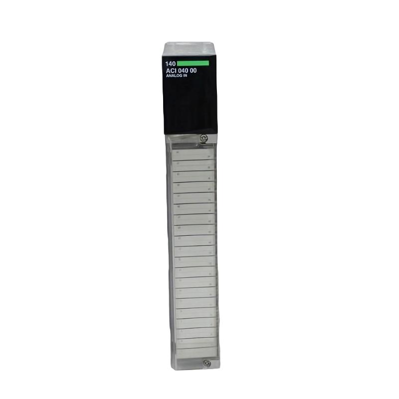
The Schneider 140ACI04000 analog input module should be installed as part of a compatible Modicon Quantum automation system, with particular attention to rack installation, field signal wiring, grounding, channel configuration, signal scaling, and commissioning. As an analog input interface, the module transfers process measurement signals from field instruments to the controller. The exact terminal assignments and supported signal characteristics should be verified against the documentation applicable to the installed 140ACI04000.
Schneider 140ACI04000 Analog Input Module Installation Overview
The 140ACI04000 is a Schneider analog input module designed to interface field instrumentation with an industrial control system. In a typical application, sensors or transmitters generate electrical signals representing process conditions, and the analog input module makes these measurements available to the controller.
Process Instrument
      |
      v
Field Signal Wiring
      |
      v
Schneider 140ACI04000
Analog Input Module
      |
      v
Quantum Rack / Backplane
      |
      v
Controller
      |
      v
PLC Logic / HMI / SCADA
Typical process applications can include monitoring temperature, pressure, flow, level, or other continuously varying process variables, depending on the connected instrumentation and configured control system.
Schneider 140ACI04000 Analog Input Module Function in an Industrial Control System
The primary function of the 140ACI04000 is to provide an analog signal interface between field instruments and the automation controller. The module receives electrical measurement signals and makes the corresponding input information available to the control application.
- Interfaces analog field instrumentation with the control system.
- Transfers process measurement information to the controller.
- Provides analog data for monitoring and control logic.
- Supports process alarms and calculations based on measured values.
- Forms part of the I/O layer of an industrial automation system.
Schneider 140ACI04000 Installation Preparation
Before installing the module, identify the intended rack position, connected instruments, channel assignments, and required signal configuration. Correct preparation is especially important for analog signals because wiring, grounding, and scaling directly affect measurement accuracy.
- Confirm the module order number: 140ACI04000.
- Inspect the module for physical damage.
- Confirm compatibility with the intended Quantum rack.
- Identify each field transmitter or sensor.
- Determine the required signal type for each application.
- Prepare appropriate instrumentation cable.
- Plan shield and grounding connections.
- Separate analog wiring from high-current and switching circuits.
- Record the existing configuration when replacing a module.
Schneider 140ACI04000 Mounting and Rack Installation
The 140ACI04000 should be installed in the appropriate Quantum rack and secured according to the applicable hardware installation procedure. Before inserting the module, inspect the backplane connector and module interface for contamination or damage.
The module should align naturally with the rack guides. Do not force the module into position because mechanical resistance may indicate incorrect alignment or a damaged connector.
- Verify the rack position before installation.
- Inspect the backplane interface.
- Align the module with the rack guides.
- Secure the module correctly.
- Keep the surrounding area accessible for maintenance.
- Maintain suitable cabinet ventilation.
Schneider 140ACI04000 Analog Signal Wiring
Field wiring should be completed with the system in a safe maintenance state. Exact terminal numbers and channel assignments should be checked against the applicable documentation rather than assumed from another Schneider analog input module.
Field Transmitter / Sensor
          |
          +---- Signal
          |
          +---- Return / Common
          |
          v
[ 140ACI04000 ]
          |
          v
Quantum Backplane
          |
          v
Controller
Analog signal cables should be routed away from motor power cables, variable-speed drive outputs, contactors, and other sources of electrical interference where practical. Shielding and grounding should follow the control-system design to avoid introducing unwanted ground-loop currents.
Schneider 140ACI04000 Channel Configuration and Setup
After the physical installation, configure the 140ACI04000 within the applicable automation engineering environment. Each channel should correspond to the actual field device connected to it.
- Confirm the module position in the rack.
- Verify that the controller recognizes the module.
- Assign the module to the appropriate hardware configuration.
- Configure the required channel characteristics.
- Verify channel addressing.
- Configure signal scaling and engineering units where required.
- Apply the validated configuration.
- Monitor the input values before enabling automatic control.
Do not assume that an existing configuration can be copied without verification. Confirm that each channel corresponds to the correct field instrument and that the engineering-unit conversion matches the actual process measurement.
Schneider 140ACI04000 Commissioning Procedure
Commissioning should proceed from the physical installation toward the process-level functional test.
Rack Installation
      |
      v
Backplane Verification
      |
      v
Field Wiring Check
      |
      v
Signal Compatibility Check
      |
      v
Controller Configuration
      |
      v
Live Input Verification
      |
      v
Scaling Verification
      |
      v
Process Functional Test
      |
      v
Final Documentation
For each channel, compare the controller value with the known field condition. Where practical, use an appropriate calibrated test source or known process condition to verify the complete measurement path.
Schneider 140ACI04000 Analog Input Validation
Validation should be performed for each active channel rather than assuming that a successfully recognized module guarantees correct field measurements.
- The module is securely installed in the rack.
- The controller recognizes the module correctly.
- Channel assignments match the system drawings.
- Field wiring is correctly terminated.
- Signal polarity and return connections are correct.
- Shielding and grounding are properly implemented.
- Input values respond to changes in the field condition.
- Scaling and engineering units are correct.
- Required process alarms and interlocks have been checked.
Schneider 140ACI04000 Field Commissioning Case
Representative example: During commissioning, one process measurement displayed by the PLC does not agree with the corresponding field instrument. The technician confirms that the 140ACI04000 is recognized by the controller and then follows the signal path.
PLC Value:
Different from field indication

Module Status:
Normal

Diagnostic Sequence:
1. Verify channel assignment
2. Verify field transmitter
3. Check signal wiring
4. Check channel configuration
5. Check scaling
6. Compare measured signal with PLC value

Result:
Configuration / wiring requires correction
This representative example shows why an incorrect analog value should be traced through the complete measurement chain. A functioning input module can still report an incorrect process value if the field wiring or configuration is wrong.
Schneider 140ACI04000 Installation FAQ
What is the Schneider 140ACI04000?
The Schneider 140ACI04000 is an analog input module used in an industrial automation system to interface suitable field analog signals with a control system.
Where is the 140ACI04000 installed?
It is installed in the appropriate Modicon Quantum rack or system configuration and communicates with the controller through the rack backplane.
What should be checked before connecting field signals?
Verify the module model, rack position, field-device signal characteristics, channel assignments, terminal wiring, shielding, grounding, and configuration.
Why is analog cable routing important?
Analog signals can be affected by electromagnetic interference. Separating instrumentation wiring from high-energy switching and motor circuits can improve signal integrity.
Why should every channel be tested during commissioning?
A module can be correctly installed while an individual channel still has incorrect wiring, configuration, scaling, or field-device conditions. Channel-by-channel testing helps identify these problems before normal operation.
Schneider 140ACI04000 Technical Summary
The Schneider 140ACI04000 analog input module provides an interface between field instrumentation and an industrial control system. Reliable operation depends on correct rack installation, field wiring, signal compatibility, grounding, channel configuration, and scaling. During commissioning or replacement, each active channel should be verified against the actual field condition before the process is returned to automatic operation.