

ProductPRODUCT
Featured products
Contact Us
- Ingersoll Rand
- 24847188
- Air/Oil Separator Element
- USA
- 610 mm
- 5.05 kg
- Xiamen, China
- New & In Stock
- T/T, PayPal, Western Union
- 1 Year
- 1-3 Working Days
- DHL, UPS, TNT, FedEx and EMS.
- 24-Hour Service
- COO
- 4
Our advantage

Global Logistics
We have a 10-year logistics and express cooperation agreement, so our products can be shipped to any place in the world.

Brand new and original
Our products are imported in bulk from the place of origin. Because of the cooperative relationship, our products are all original and 100% new.

24-hour service
We provide 7*24 hours service to our customers. We will be there whenever you need us.

Price advantage
All our products are priced very favorably because we have our own warehouse and supply.
| Company Information | |||
| [email protected] | |||
| Mobile | +8615980777398 | ||
| +8615980777398 | |||
| 15980777398 |
Product Overview
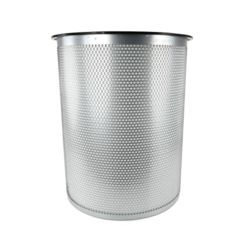
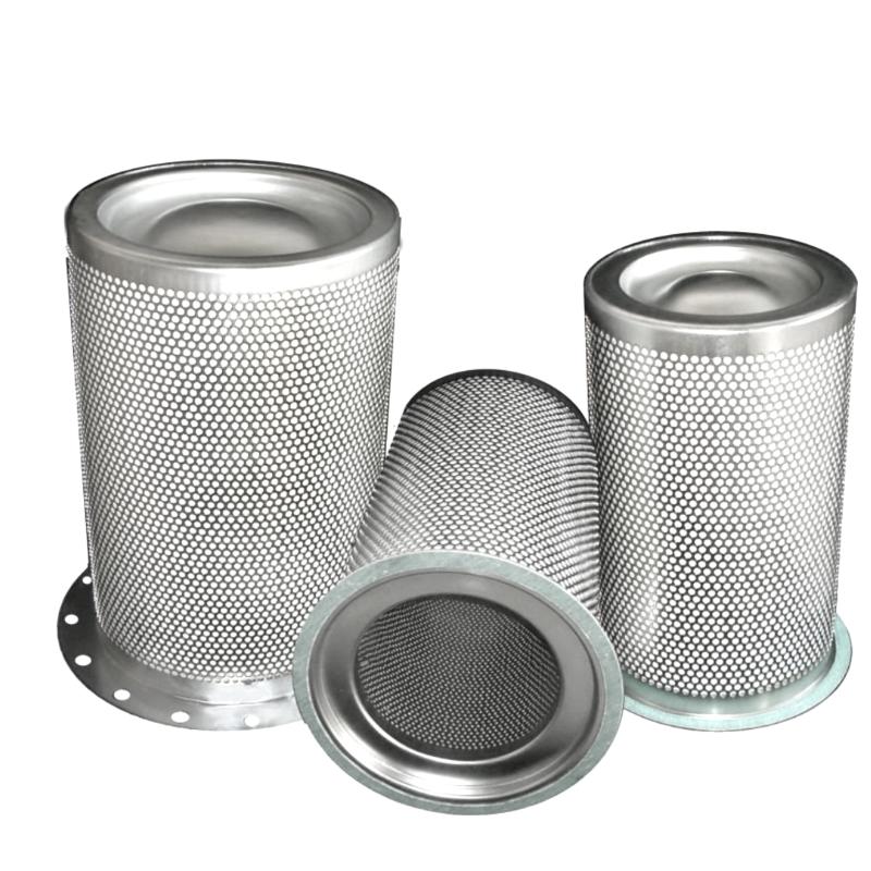
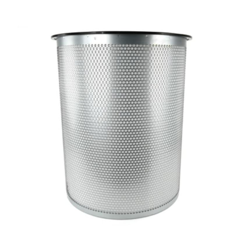
The Ingersoll Rand 24847188 Air/Oil Separator Element is a replacement separation component used in industrial compressed-air systems. Its primary function is to remove suspended lubricant droplets from compressed air after the compression process, allowing recovered oil to return to the compressor lubrication circuit.
In an oil-injected rotary screw compressor, lubricant is introduced into the compression chamber to cool the rotors, seal internal clearances, and reduce friction. During compression, some of this oil becomes mixed with the compressed air. Before the air can enter the downstream distribution system, most of the entrained lubricant must be separated and recovered.
The 24847188 is identified as an Element, Separator 610MM Tank, indicating its application in a separator tank with a 610 mm tank configuration. This is an important selection characteristic because separator elements are matched to the mechanical arrangement of the tank, including the available installation space, sealing surfaces, and oil recovery connection.
Inside the separator vessel, the element provides a coalescing filtration stage. Fine oil droplets carried by compressed air collect on the separator media and combine into larger droplets. These droplets gradually drain toward the bottom of the element, where the recovered lubricant can be collected and returned through the oil return system.
The element is particularly relevant to large industrial compressor installations where compressed-air production and lubricant circulation operate continuously. In manufacturing plants, petrochemical facilities, and other industrial environments, maintaining the separation stage helps control oil carryover and protects downstream compressed-air equipment.
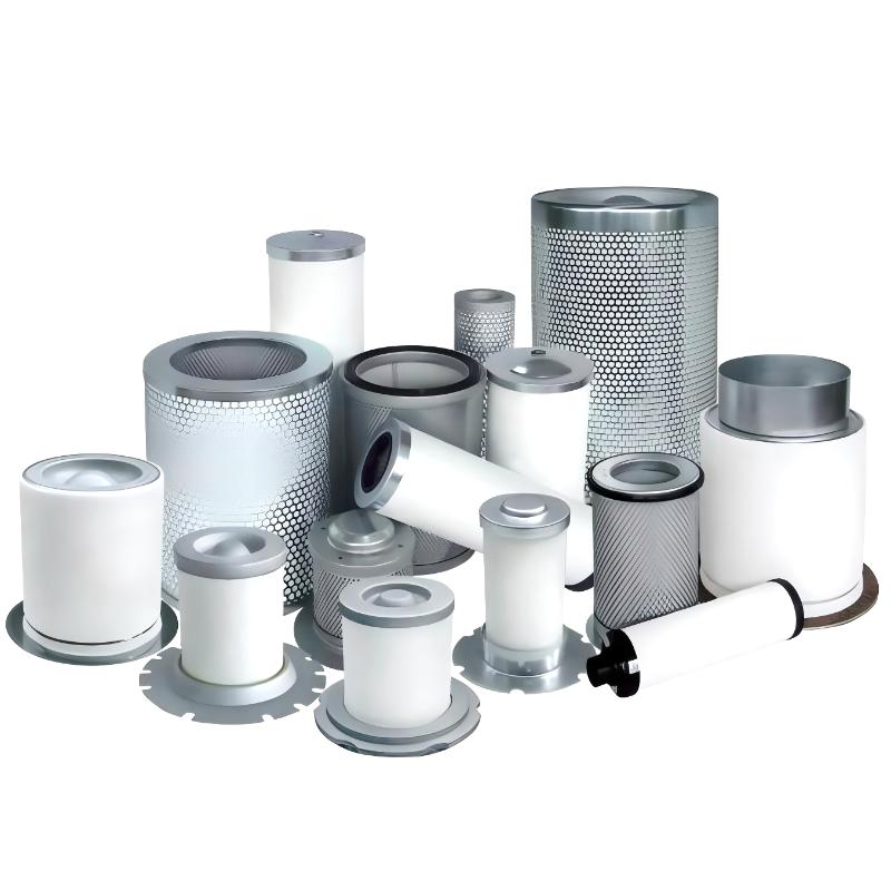
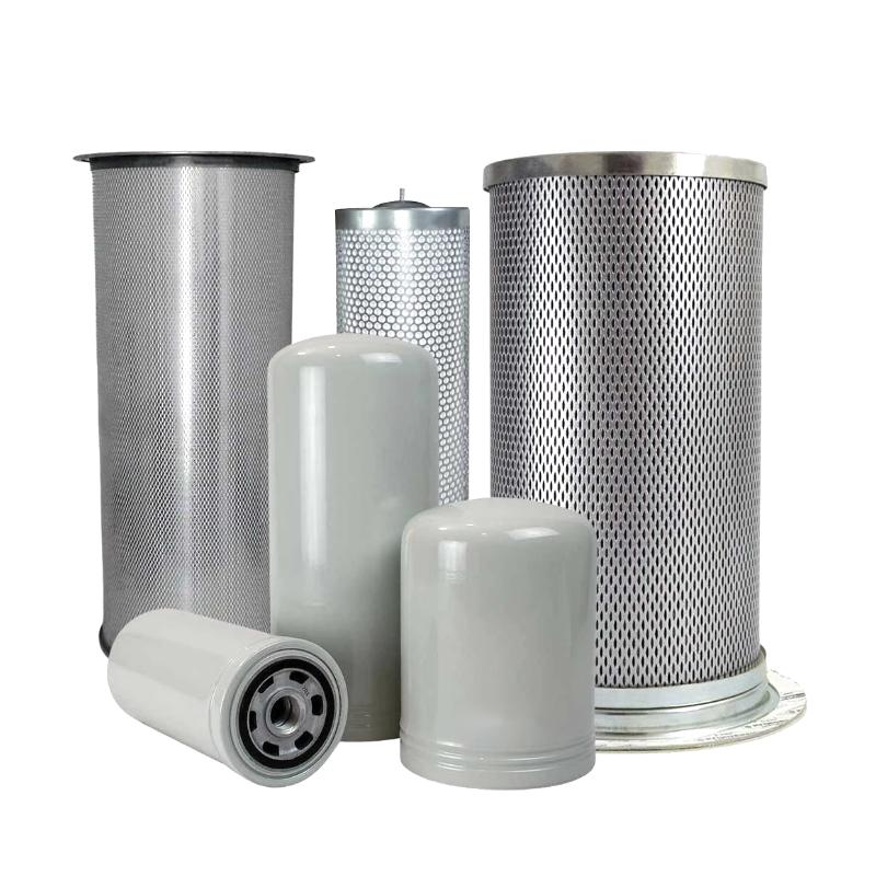
The 610 mm separator tank specification distinguishes this component from smaller spin-on separator cartridges used in compact compressor packages. Replacement selection should therefore consider the separator tank configuration rather than relying solely on the general product description.
During routine maintenance, the condition of the separator element should be evaluated together with differential pressure, oil carryover, and the condition of the oil return line. A restricted or damaged element can affect the compressor’s discharge conditions and increase the amount of lubricant entering the compressed-air system.
Technical Specifications
| Parameter | Specification |
|---|---|
| Manufacturer | Ingersoll Rand |
| Model | 24847188 |
| Product Type | Air/Oil Separator Element |
| Component Description | Element, Separator 610MM Tank |
| Application | Industrial Air Compressor |
| Compressor Type | Oil-Injected Compressed-Air System |
| Installation Position | Separator Tank |
| Compatible Separator Tank Size | 610 mm |
| Separation Principle | Coalescing Filtration |
| Separation Function | Removal of Oil Droplets from Compressed Air |
| Weight | 5.05 kg |
Product Features
- 610 mm Tank Configuration: Specified for the corresponding large separator tank arrangement.
- Oil Aerosol Separation: Captures suspended lubricant droplets carried by compressed air.
- Coalescing Filter Media: Combines fine oil droplets into larger droplets that can drain from the filtration structure.
- Lubricant Recovery: Supports the return of separated oil to the compressor lubrication circuit.
- Compressed-Air Quality Control: Helps limit oil carryover into downstream air equipment.
- Industrial Compressor Application: Suitable for maintenance of compatible oil-injected compressor systems.
- Replaceable Separator Element: Allows the separation stage to be serviced without replacing the complete separator tank assembly.
Working Principle
The 24847188 operates through a coalescing separation process inside the compressor’s separator tank. Its purpose is to remove lubricant that remains suspended in the compressed-air stream after the initial oil separation process.
The separation process generally follows this sequence:
Air/Oil Mixture → Separator Tank → 24847188 Separator Element → Filtered Compressed Air → Minimum Pressure Valve → Aftercooler / Air Distribution System
When compressed air containing oil droplets enters the separator vessel, the initial reduction in airflow velocity allows part of the heavier oil to separate from the air through gravity and centrifugal effects, depending on the tank arrangement.
The remaining air passes through the separator element. Its filtration media captures fine oil droplets as the compressed air moves through the element. These droplets accumulate on the media and gradually combine into larger droplets through coalescence.
Once the droplets become sufficiently large, gravity causes them to move toward the lower collection area of the separator element. The recovered lubricant is then directed through the oil return or scavenge circuit, where it can be returned to the compressor’s lubrication system.
For example, in a large rotary screw compressor operating continuously in a manufacturing plant, the separator element handles a constant flow of compressed air containing residual lubricant. As the element performs its separation function, the recovered oil is returned to the lubrication circuit while the compressed air continues toward downstream equipment.
The pressure differential across the element is another important operating characteristic. As the media accumulates contaminants or becomes restricted, airflow resistance increases. Excessive differential pressure can increase compressor energy consumption and affect discharge performance.
For this reason, the 24847188 should be maintained as part of the complete separator system. The separator element, oil return line, scavenge components, tank sealing surfaces, and minimum pressure valve all contribute to the overall separation process.
Role in the Compressor Air/Oil Separation System
The 24847188 occupies the main coalescing filtration position within the separator tank. It separates residual lubricant from compressed air after the initial separation stage and supports the recovery of that lubricant into the compressor’s oil circulation system.
A typical oil-injected compressor arrangement follows this sequence:
Airend → Separator Tank → 24847188 Air/Oil Separator Element → Minimum Pressure Valve → Aftercooler → Compressed-Air Network
| System Component | Function |
|---|---|
| Airend | Compresses incoming air while mixing it with circulating lubricant |
| Separator Tank | Receives the compressed air and oil mixture and provides the initial separation space |
| 24847188 Separator Element | Captures residual oil droplets through coalescing filtration |
| Oil Collection Area | Collects lubricant separated from the compressed-air stream |
| Scavenge Line | Returns collected oil to the appropriate point in the lubrication circuit |
| Scavenge Orifice | Controls the return flow of recovered lubricant |
| Minimum Pressure Valve | Maintains the required pressure within the compressor system |
| Aftercooler | Reduces compressed-air temperature before downstream delivery |
| Oil Cooler | Removes heat from circulating compressor lubricant |
| Compressor Controller | Monitors operating conditions and relevant maintenance indications |
The separator element and oil return circuit must operate together. Even when the filter media remains in good condition, a blocked scavenge line or incorrectly positioned return tube can prevent collected oil from returning properly.
Excessive oil carryover can also affect downstream equipment, including air dryers, filters, pneumatic control devices, and production machinery. Maintaining the separator assembly helps reduce this risk and supports the intended compressed-air quality.
The 610 mm tank configuration should be checked when replacing the element. A separator with a different physical arrangement may have different sealing, mounting, and oil recovery requirements even if its general filtration function is similar.
Industrial Applications
| Application | Typical Use |
|---|---|
| General Manufacturing | Controlling oil carryover in centralized compressed-air systems |
| Automotive Production | Maintaining compressed-air quality for pneumatic production equipment |
| Petrochemical Facilities | Separating lubricant from compressed air in industrial compressor installations |
| Chemical Processing | Supporting oil recovery and compressed-air separation |
| Power Generation | Maintaining separator performance in auxiliary compressor systems |
| Metalworking Facilities | Supporting compressed-air supply for production machinery |
| Textile Manufacturing | Reducing lubricant contamination in plant compressed-air networks |
| Heavy Industry | Maintaining air/oil separation in large compressor installations |
| Industrial Utilities | Supporting continuous compressed-air production |
| Process Manufacturing | Maintaining separation performance in oil-injected compressor systems |
Installation and Maintenance
- Verify the Part Number: Confirm that 24847188 matches the required 610 mm separator tank configuration. Check the compressor identification and existing separator element before beginning maintenance.
- Shut Down the Compressor: Stop the compressor and isolate the electrical supply according to the site’s lockout and maintenance procedures.
- Depressurize the Separator Tank: Allow the system to cool and verify that the separator vessel has reached zero internal pressure before opening the tank.
- Drain the Lubricant: Drain or isolate the compressor oil according to the applicable service procedure to prevent lubricant from spilling during element removal.
- Open the Separator Tank: Remove the tank cover fasteners in the prescribed sequence. Lift the cover carefully to avoid damaging the sealing surfaces or attached oil return components.
- Remove the Existing Element: Carefully withdraw the used separator element. Prevent accumulated contaminants from entering the clean-air outlet or the oil return passages.
- Inspect the Separator Vessel: Check the tank interior for oil deposits, sludge, corrosion, and loose debris. Clean the internal surfaces using an appropriate maintenance procedure.
- Check the Oil Return System: Inspect the scavenge tube, orifice, return line, and associated fittings for blockage or damage. These components must remain clear for proper recovery of separated lubricant.
- Inspect the Sealing Surfaces: Examine the tank cover and element seating areas. Replace damaged gaskets and sealing components as required.
- Install the New Element: Position the 24847188 correctly inside the separator tank. Ensure that the element sits evenly and that its sealing arrangement is not displaced during installation.
- Reassemble and Test: Reinstall the tank cover and tighten the fasteners in the specified sequence. Restore the oil supply, restart the compressor according to its commissioning procedure, and inspect for leaks and abnormal differential pressure.
- Record Maintenance Information: Document the replacement part number, date, operating hours, separator differential pressure, and condition of the recovered lubricant and scavenge components.
Compatible System Components
| Component | Function |
|---|---|
| Ingersoll Rand 24847188 | Air/oil separator element for 610 mm separator tank |
| Separator Tank Assembly | Houses the separator element and initial oil separation area |
| Separator Tank Cover | Secures the element and closes the separator vessel |
| Separator Gasket | Seals the element and tank interfaces |
| Oil Scavenge Tube | Collects and returns separated lubricant |
| Scavenge Orifice | Regulates recovered oil flow |
| Oil Return Line | Directs recovered lubricant back into the lubrication circuit |
| Minimum Pressure Valve | Maintains the required compressor system pressure |
| Oil Cooler | Controls circulating lubricant temperature |
| Air/Oil Separator Housing | Supports the complete separation assembly |
Recommended Related Models
| Model / Component | Product Type | Typical Application |
|---|---|---|
| Ingersoll Rand 23545841 | Air/Oil Separator Element | Compressor oil separation maintenance |
| Ingersoll Rand 24900342 | Separator Element | Alternative compressor separator configuration |
| Ingersoll Rand 54749247 | Separator Cartridge | Compressor air/oil separation |
| Ingersoll Rand 54672654 | Separator Cartridge | Compressor separation system maintenance |
| Ingersoll Rand 92871326 | Separator Element | Related industrial compressor separation component |
| Ingersoll Rand 54601513 | Separator Element | Separator tank filtration maintenance |
Key Advantages
- Designed for the 610 mm separator tank configuration.
- Removes residual oil droplets from compressed air.
- Supports recovery of lubricant into the compressor oil circuit.
- Helps control oil carryover into downstream compressed-air equipment.
- Coalescing filtration supports separation of fine oil aerosols.
- Replaceable element for scheduled separator maintenance.
- Supports the operation of large industrial oil-injected compressor systems.
Technical FAQs
What does the 610 mm specification mean for the Ingersoll Rand 24847188?
The 610 mm designation identifies the separator tank configuration associated with this element. It is a tank-size reference, not the outer diameter or height of the filter element. When selecting a replacement, the separator tank arrangement must match the specified application.
What happens when the 24847188 separator element becomes restricted?
As the separator media accumulates contaminants, resistance to airflow increases and the differential pressure across the element may rise. This can increase compressor energy consumption and affect compressed-air delivery. Excessive restriction may also indicate that the element has reached its replacement condition.
Can excessive oil carryover be caused by something other than a damaged separator element?
Yes. Oil carryover can also result from problems in the oil return system, including a blocked scavenge orifice, damaged return tubing, or incorrect oil return positioning. Excessive oil level and unsuitable operating conditions can also contribute. The complete separator assembly should be inspected before replacing components unnecessarily.
How should the 24847188 be selected when replacing an existing separator?
The 610 mm separator tank specification and part number should be checked against the installed compressor configuration. The tank cover, element seating arrangement, gasket interface, and oil return connection should also be examined. Matching only the general separator function is insufficient to establish mechanical compatibility.