
NewsNEWCENTER
Featured products
Contact Us
GE IC200CHS101 Disconnect-Style Interposing I/O Terminal – Main Base Installation and Setup Guide
2026-11-10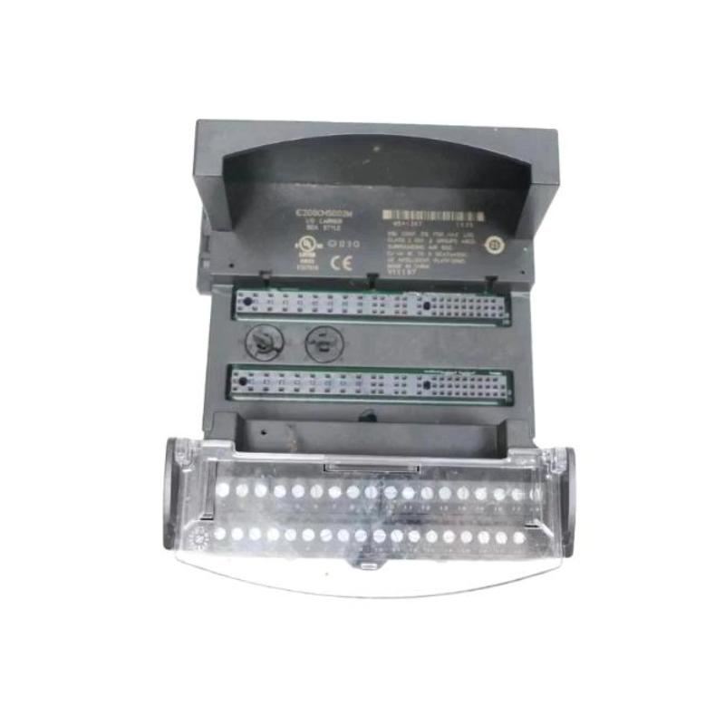
1. Product Overview
The GE IC200CHS101 is a Disconnect-Style Interposing I/O Terminal Main Base designed for the GE Fanuc VersaMax PLC system. It provides an interface between a VersaMax connector-style I/O carrier and field wiring, while incorporating individual disconnect switches for field signal circuits.
The main purpose of the IC200CHS101 is to simplify field wiring and maintenance. Its disconnect switches allow individual signal or return paths to be isolated without removing field wiring or disturbing the rest of the installation. This is particularly useful in industrial control cabinets where technicians need to inspect, test, or service individual I/O circuits.
The IC200CHS101 is the main base and provides connections for the A-side terminals of a compatible VersaMax I/O module. When an application requires access to the B-side terminals, the corresponding IC200CHS102 Expansion Base is required.
2. Technical Specifications
| Parameter | Description |
|---|---|
| Manufacturer | GE Fanuc / GE |
| Model | IC200CHS101 |
| Product type | Disconnect-Style Interposing I/O Terminal |
| Base type | Main Base |
| Product family | VersaMax PLC |
| Carrier connection | J1 connector |
| Expansion connection | J2 connector |
| Field wiring terminals | 36 box-style terminals |
| Primary I/O connection | A-side terminals A1–A18 |
| Auxiliary common terminals | W1–W8 and X1–X8 |
| Disconnect mechanism | Individual knife-switch disconnects |
| Expansion model | IC200CHS102 |
| Approximate dimensions | 115 × 126 × 65 mm |
Dimensions are approximate and should be checked against the physical installation requirements. Electrical ratings, wire sizes, and module compatibility must be confirmed using the documentation for the exact I/O module and terminal arrangement.
3. Main Functions and Operating Principle
3.1 Field Wiring Interface
The IC200CHS101 provides 36 box-style terminals for field I/O wiring and power connections. It connects to a VersaMax connector-style I/O carrier through its J1 connector, creating an organized interface between the PLC hardware and external devices.
Instead of connecting field wiring directly at the I/O carrier, technicians can terminate the field conductors at the interposing base. This arrangement can make cabinet wiring easier to organize and simplify maintenance activities.
3.2 Individual Circuit Disconnection
One of the defining features of the IC200CHS101 is its individual knife-switch disconnect mechanism. Each supported signal and common terminal has a corresponding disconnect point. Opening the appropriate switch can isolate an individual field circuit from the control circuit.
This arrangement allows technicians to take selected inputs or outputs offline for inspection or testing without necessarily changing the wiring of other circuits. The actual effect of opening a disconnect depends on the signal arrangement and the connected I/O module.
3.3 A-Side I/O Connection
The IC200CHS101 provides connections for the A-side terminals of the VersaMax connector, identified as A1 through A18. It also includes two groups of auxiliary common terminals, W1–W8 and X1–X8, which can support two-wire field-device connections.
Terminal assignments must follow the wiring diagram for the installed I/O module. Do not assume that terminal numbers correspond to identical signal functions across different VersaMax modules.
3.4 Expansion Capability
The J2 expansion connector allows the IC200CHS101 to connect to an IC200CHS102 Disconnect-Style Interposing I/O Expansion Base. The expansion base provides the B-side connections for modules that require them, together with additional auxiliary terminals.
The IC200CHS101 and IC200CHS102 serve different roles. The expansion base should only be added when required by the I/O module and the system wiring design.
4. Installation Preparation
4.1 Verify Hardware Compatibility
Before installation, confirm that the selected VersaMax I/O module is compatible with the IC200CHS101. Not every I/O module uses the same terminal arrangement, and some modules may require an additional expansion base or a different interposing terminal type.
Check the following information:
- Complete IC200CHS101 model number.
- VersaMax I/O module model and terminal arrangement.
- Connector-style I/O carrier model.
- Required A-side and B-side field connections.
- Field wiring diagram and terminal assignments.
- Whether an IC200CHS102 expansion base is required.
4.2 Prepare Tools and Materials
- Appropriate insulated hand tools.
- Approved wire preparation and termination tools.
- Labels for identifying field conductors.
- Suitable mounting hardware and DIN rail or panel provisions.
- ESD protection for handling associated electronic equipment.
- Approved electrical test equipment.
- Current system wiring diagrams and module documentation.
4.3 Electrical Safety
Before connecting or disconnecting field wiring, follow the site’s isolation and lockout/tagout procedures. Identify all relevant power sources, including external field-device supplies. Verify that the circuits are in a safe state before working on the terminal assembly.
Do not assume that opening an individual knife switch makes every part of the field circuit electrically safe. External power sources or other wiring paths may remain energized. Follow the plant’s electrical safety procedures and the module-specific maintenance instructions.
5. IC200CHS101 Installation Procedure
Step 1: Inspect the Terminal Base
Check the IC200CHS101 for physical damage before installation. Inspect the terminal blocks, J1 connector, J2 expansion connector, switch mechanisms, and mounting features. Do not install a base with cracked housing, damaged contacts, or defective disconnect mechanisms.
Step 2: Mount the Main Base
Install the terminal base in the designated control cabinet location. It can be mounted on a suitable DIN rail or on a panel according to the system layout and installation requirements.
Ensure that the mounting arrangement provides adequate mechanical support, access to field wiring terminals, and sufficient clearance for connector installation and maintenance. Where vibration or mechanical shock is a concern, use the additional panel mounting provisions specified by the equipment documentation.
Step 3: Connect the VersaMax Carrier
Use the approved cable to connect the IC200CHS101 J1 connector to the compatible VersaMax connector-style I/O carrier. Confirm connector orientation and alignment before mating the connection.
Do not force the connector into position. Check that the cable is correctly routed and secured so that it does not place unnecessary mechanical stress on the connector.
Step 4: Connect Field Wiring
Connect the field conductors to the appropriate terminals according to the wiring diagram for the specific I/O module. The IC200CHS101 provides A1–A18 connections and auxiliary W1–W8 and X1–X8 terminal groups.
For each conductor:
- Confirm the terminal designation before making the connection.
- Verify conductor type and size against the terminal specifications.
- Prepare the conductor using the correct stripping length.
- Ensure that the conductor is securely retained.
- Label the wiring to support future maintenance.
- Check for loose strands or exposed conductor that could cause an unintended connection.
Do not use a generic terminal map for all VersaMax modules. The module-specific wiring diagram determines the correct signal and common connections.
Step 5: Configure the Disconnect Switches
Review the required operating state of each disconnect switch before commissioning. The switches are provided to isolate individual signal or common paths when required for maintenance or testing.
Confirm that each switch is in the intended position for normal operation. Do not open or close switches randomly during commissioning, as doing so may interrupt field signals or affect control logic.
Step 6: Install the Expansion Base if Required
If the selected I/O module requires B-side connections, install the compatible IC200CHS102 expansion base. Connect it to the IC200CHS101 through the J2 expansion connection using the specified ribbon cable.
Check the mechanical fit, connector alignment, cable routing, and terminal assignments. The expansion base provides B1–B18 connections and auxiliary Y1–Y8 and Z1–Z8 terminal groups.
6. Commissioning and Functional Checks
6.1 Pre-Power Inspection
Before restoring power, inspect the completed installation:
- Confirm that the terminal base is securely mounted.
- Verify that the J1 carrier connection is correctly installed.
- Check J2 and the expansion cable if an IC200CHS102 is used.
- Compare all field connections with the module wiring diagram.
- Check that conductors are properly terminated and identified.
- Confirm the intended position of each disconnect switch.
- Check that no tools or loose materials remain inside the cabinet.
6.2 Restore Power and Check System Status
Restore power according to the approved plant startup procedure. Check the VersaMax PLC and associated I/O module status indications. Confirm that the controller recognizes the installed hardware and that no unexpected I/O-related faults are reported.
6.3 Verify Individual Field Signals
Use the PLC diagnostics and approved field test procedure to verify the connected inputs and outputs. Compare the observed signal states with the actual field-device conditions and the application wiring documentation.
If a signal is missing, check the relevant field device, wiring termination, disconnect-switch position, module configuration, and carrier connection before concluding that the IC200CHS101 is defective.
6.4 Verify Disconnect Functionality
Where operationally permitted, verify the disconnect function on an individual circuit using an approved test plan. Confirm that the selected circuit responds as expected and that unrelated circuits remain in their intended operating states.
Perform this test only after assessing the process impact of interrupting the selected signal. Do not disconnect safety-critical or process-critical signals without the required authorization and operating controls.
7. System Integration and Application Considerations
The IC200CHS101 is an interposing terminal base rather than a standalone PLC controller or I/O processing module. Its function is to provide a field wiring interface and individual circuit disconnection for a compatible VersaMax I/O arrangement.
Typical applications include:
- Industrial machine control cabinets.
- Manufacturing automation systems.
- Process control and monitoring panels.
- Distributed field I/O installations.
- Systems requiring individual field-circuit isolation for maintenance.
For correct integration, the I/O module, connector-style carrier, interposing terminal base, field wiring, and PLC configuration must be treated as one coordinated assembly. Compatibility should be checked against the actual module rather than determined by the terminal base model alone.
8. Maintenance Recommendations
- Inspect terminal connections during scheduled maintenance.
- Check the J1 and J2 connectors for mechanical damage or poor seating.
- Verify that disconnect switches move correctly and are not obstructed.
- Look for signs of overheating, corrosion, contamination, or moisture.
- Keep terminal labels and wiring diagrams up to date.
- Check mounting security where vibration is present.
- Record any field-circuit isolation or wiring changes.
Before tightening or modifying any connection, follow the required isolation procedure and use the specified terminal torque where applicable. Do not apply an assumed torque value.
9. Frequently Asked Questions
What is the GE IC200CHS101?
The IC200CHS101 is a Disconnect-Style Interposing I/O Terminal Main Base for the GE Fanuc VersaMax PLC system. It provides field wiring terminals and individual disconnect switches for supported I/O circuits.
What is the difference between IC200CHS101 and IC200CHS102?
The IC200CHS101 is the main base and provides A-side connections. The IC200CHS102 is the expansion base and provides B-side connections for compatible I/O modules that require them.
What are the J1 and J2 connectors used for?
J1 connects the main base to the VersaMax connector-style I/O carrier. J2 is the expansion connection used when connecting a compatible IC200CHS102 expansion base.
Can individual field signals be disconnected?
Yes. The base provides individual knife-switch disconnects for supported signal and common paths. The effect of each switch depends on the connected module and wiring arrangement.
Does the IC200CHS101 process PLC signals?
No. It provides a field wiring and disconnection interface. Signal processing is performed by the compatible VersaMax I/O module.
Can the IC200CHS101 be used with every VersaMax I/O module?
No. Compatibility depends on the I/O module’s terminal arrangement and the system configuration. Check the module compatibility information before installation.
10. Conclusion
The GE IC200CHS101 Disconnect-Style Interposing I/O Terminal Main Base provides a practical field wiring interface for compatible GE Fanuc VersaMax PLC installations. Its A-side terminal connections, auxiliary common terminals, J1 carrier interface, J2 expansion connector, and individual disconnect switches support organized wiring and selective circuit isolation.
Correct installation depends on selecting a compatible I/O module, following its wiring diagram, securing all connections, and verifying the disconnect-switch positions before commissioning. When B-side connections are required, the IC200CHS102 expansion base must be incorporated into the design. Careful installation and periodic inspection help maintain reliable field I/O connections and simplify industrial control system maintenance.
Technical Summary
The GE IC200CHS101 is a VersaMax Disconnect-Style Interposing I/O Terminal Main Base with 36 box-style field wiring terminals, a J1 connector for the connector-style I/O carrier, and a J2 connector for expansion. It provides A-side connections A1–A18, auxiliary common terminals W1–W8 and X1–X8, and individual knife-switch disconnects for supported signal and common paths. It is used with compatible VersaMax I/O modules and may be paired with the IC200CHS102 expansion base when B-side connections are required.