
NewsNEWCENTER
Featured products
Contact Us
GE 1719-0023 Analog Main Board Troubleshooting Guide
2026-10-13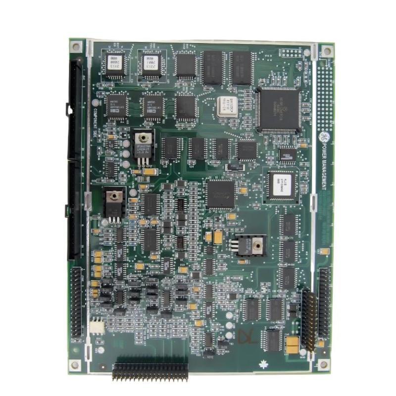
The GE 1719-0023 Analog Main Board may be suspected when an industrial control system develops abnormal signal behavior, startup alarms, intermittent operation, or a board-recognition problem. Accurate diagnosis requires separating board-related faults from external wiring, power supply, grounding, configuration, and host-system problems. This GE 1719-0023 Analog Main Board troubleshooting guide presents a structured approach to fault identification, safe testing, repair assessment, and replacement decisions.
1. GE 1719-0023 Analog Main Board Fault Symptoms
The symptoms observed in the field depend on the equipment that uses the board and its actual function within that system. The following are general symptoms that may justify investigation; they are not a verified list of model-specific fault codes.
- Board recognition failure: The host equipment does not detect or initialize the installed assembly.
- Abnormal signal values: A connected signal appears missing, unstable, offset, or inconsistent with the expected operating condition.
- Intermittent operation: The system operates normally at some times but develops recurring alarms or signal interruptions.
- Startup problems: The equipment reports a fault after maintenance, board replacement, or a configuration change.
- Visible physical damage: Connectors, components, or circuit-board areas show discoloration, corrosion, cracking, or other damage.
- Repeated system alarms: The host controller reports an issue associated with the relevant assembly or its connected interface.
None of these symptoms alone proves that the GE 1719-0023 is defective. Diagnosis should begin with the simplest external causes and progress to board-level investigation only when supported by evidence.
2. GE 1719-0023 Troubleshooting Safety and Preparation
Industrial control assemblies may be installed in equipment containing hazardous voltages, stored energy, rotating machinery, or process-related risks. Troubleshooting must be performed by appropriately qualified personnel under the site’s approved maintenance procedure.
- Review active alarms, recent maintenance work, and operating history before disturbing the equipment.
- Establish the required safe state and apply lockout/tagout where applicable.
- Verify isolation and discharge stored energy according to the equipment procedure.
- Use electrostatic discharge protection when handling the circuit board.
- Use only approved test points and instruments suitable for the electrical environment.
- Never bypass safety interlocks or protective circuits to keep the equipment running.
Do not disconnect or reconnect board connectors under power unless the equipment documentation explicitly permits that procedure and it is performed by qualified personnel.
3. GE 1719-0023 Initial Fault Diagnosis
3.1 Record the Original Symptoms
Before resetting alarms or replacing components, record the exact alarm text, occurrence time, affected function, operating conditions, and any available diagnostic information. Determine whether the fault began after a board replacement, wiring modification, power event, cabinet maintenance, or software change.
3.2 Inspect the Board and Connectors
With the equipment safely isolated, inspect the GE 1719-0023 and its surrounding assembly for:
- Loose, damaged, or contaminated connectors.
- Corrosion, moisture, or conductive dust.
- Cracked solder joints or visible component damage.
- Signs of overheating or discoloration.
- Incorrect board orientation or incomplete seating.
- Pinched cables, strained connections, or damaged insulation.
Visual inspection can reveal obvious defects but cannot establish that a board is electrically functional. A board with no visible damage may still contain a failed component or interface circuit.
3.3 Verify Power and Grounding
Check the supply and grounding arrangements against the host system’s approved documentation. Confirm that relevant supplies are present and stable at the specified test points, and investigate abnormal voltage, excessive ripple, loose ground connections, or supply interruptions where appropriate.
Do not assume a supply voltage, connector pinout, or test point based on the board name. Applying a test voltage to an unidentified pin can cause additional damage.
4. GE 1719-0023 Analog Signal Fault Troubleshooting
4.1 Determine Whether the Fault Is External or Board-Related
If the reported issue involves an analog signal, verify the source device and wiring before concluding that the main board has failed. Depending on the host system, possible external causes include a faulty transmitter, damaged cable, loose terminal, incorrect channel assignment, grounding issue, or an unsuitable signal range.
A representative diagnostic path is shown below. It is a general troubleshooting sequence, not a verified internal circuit diagram for the GE 1719-0023.
Reported Signal or Control-System Fault
                 |
                 v
Read Host-System Diagnostics
                 |
                 v
Check External Device and Wiring
                 |
                 v
Verify Power, Grounding and Configuration
                 |
                 v
Test Through Approved Procedures
                 |
        +--------+--------+
        |                 |
   External Fault     Fault Persists
        |                 |
 Correct Wiring,      Assess Board and
 Source or Setup      Host Interface
        |                 |
        +--------+--------+
                 |
                 v
Controlled Functional Verification
4.2 Compare Related Signals or Channels
Where the system design and maintenance procedure allow, compare the affected signal with a known-good reference or another equivalent channel. Ensure that the comparison uses the same signal type, operating conditions, and configuration. A discrepancy may help narrow the problem to the field device, wiring, configuration, or electronic assembly, but it does not independently confirm board failure.
4.3 Check Configuration and Calibration
After a replacement or system change, verify channel mapping, scaling, calibration data, and any applicable hardware settings. Incorrect configuration can produce abnormal readings that resemble an electronic fault. Restore settings only through the approved engineering procedure and preserve a record of changes.
5. GE 1719-0023 Common Faults and Corrective Actions
5.1 Board Not Detected by the Host System
Possible causes include incomplete connector engagement, incompatible hardware revision, damaged interface contacts, missing supply power, or a host-system configuration problem.
- Record the system diagnostic message.
- Verify part-number and revision compatibility.
- Inspect the board and mating connectors under safe, isolated conditions.
- Confirm relevant power and interface requirements using the equipment documentation.
- If available, use an approved substitution test with a compatible known-good assembly.
5.2 Signal Readings Are Unstable or Incorrect
Investigate the signal source, wiring condition, shielding, grounding, configuration, and calibration before replacing the board. Electrical noise, intermittent field wiring, or an incorrect scaling setting may create symptoms similar to a defective signal-processing circuit.
5.3 Faults Appear Intermittently
Intermittent problems may be associated with loose connectors, temperature-related component behavior, vibration, power instability, or a field device that fails under certain operating conditions. Record the conditions under which the problem occurs and look for a repeatable relationship. Do not manipulate energized connectors to provoke a fault.
5.4 The Board Shows Signs of Overheating
Discoloration, burnt odor, or visibly damaged components warrant immediate investigation. Isolate the equipment and check for the underlying cause, including supply problems, shorts, contamination, poor connections, or environmental conditions. Do not return a visibly damaged board to service simply because the equipment starts successfully afterward.
5.5 Fault Persists After Board Replacement
If replacing the GE 1719-0023 does not resolve the issue, reconsider the original diagnosis. Investigate external signal sources, host interfaces, system configuration, power quality, and associated assemblies. Confirm that the replacement board is compatible and properly configured before concluding that the host equipment itself is defective.
6. GE 1719-0023 Board Testing and Repair Assessment
Board-level testing should follow the approved service procedure for the specific equipment. Depending on available documentation and test facilities, qualified technicians may inspect connector continuity, check specified supply rails, review diagnostic data, and perform approved functional tests.
Do not perform arbitrary resistance or continuity measurements on powered circuitry. Before using a meter, confirm that the equipment is isolated and that the selected measurement method is appropriate for the circuit. Avoid applying external signals to unidentified terminals.
6.1 When Repair May Be Appropriate
Professional repair may be considered when the failure has been localized, suitable technical information is available, and the repair facility can perform appropriate inspection and functional testing. Repair decisions should account for component availability, circuit-board condition, safety requirements, and the consequences of an unexpected failure in the host process.
6.2 When Replacement Is Preferable
- The board has extensive heat damage, corrosion, or physical damage.
- The fault cannot be isolated using approved test methods.
- Required components or reliable repair information are unavailable.
- The application requires a validated assembly with traceable maintenance records.
- A repaired board cannot pass the necessary functional verification.
Replacement hardware should be verified for exact part number, revision, connector configuration, and host-system compatibility. Similar-looking boards are not necessarily interchangeable.
7. GE 1719-0023 Post-Repair and Post-Replacement Verification
After repair or replacement, follow the host system’s commissioning procedure. Check for recurring alarms, confirm board recognition where supported, and validate relevant signals or functions using approved test conditions.
- Confirm that all connectors, retainers, and covers are correctly installed.
- Restore the approved configuration and calibration settings if required.
- Power up the equipment using the designated startup sequence.
- Review diagnostic messages and confirm that the original symptom has cleared.
- Perform controlled functional checks before returning the equipment to normal operation.
- Record the repair or replacement, test results, and any remaining limitations.
8. GE 1719-0023 Troubleshooting FAQs
Does an analog signal fault always indicate a defective GE 1719-0023?
No. External transmitters, field wiring, grounding, power supplies, configuration, and host-system interfaces can produce similar symptoms. Check these causes before condemning the board.
Can the GE 1719-0023 be repaired at component level?
Potentially, but repair depends on the actual fault, circuit design, available documentation, and suitable test facilities. Board-level work should be performed by qualified technicians using approved procedures.
What information is most useful when diagnosing the board?
Useful information includes the full part number and revision, host-equipment identification, exact alarm text, affected function, recent maintenance history, supply measurements taken at approved test points, and the results of controlled functional checks.
Why does the same fault remain after replacing the board?
The original cause may be outside the board, such as external wiring, a field device, the host interface, an incompatible replacement, or incorrect configuration. Reassess the complete signal and control path.
Should the board be replaced if there is no visible damage?
Not automatically. Electrical faults may not be visible, but replacement should be based on diagnostic evidence, compatibility checks, and approved testing rather than appearance alone.
9. GE 1719-0023 Analog Main Board Troubleshooting Technical Summary
Effective troubleshooting of the GE 1719-0023 Analog Main Board begins with accurate symptom recording, safe inspection, verification of power and grounding, and systematic checks of external signals and system configuration. Board replacement or repair should follow only when the evidence supports a board-related fault. By using approved test points, preserving configuration records, and verifying system operation after corrective work, maintenance teams can reduce repeat failures and avoid unnecessary component replacement.