

ProductPRODUCT
Featured products
Contact Us
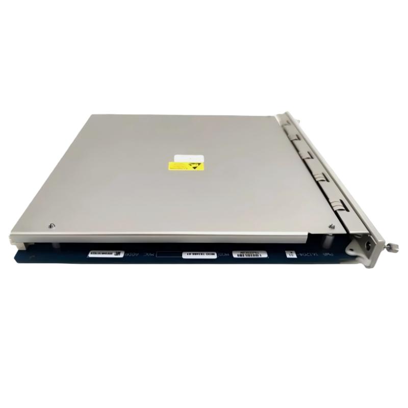
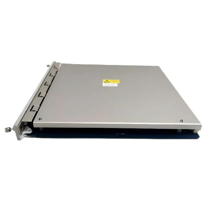
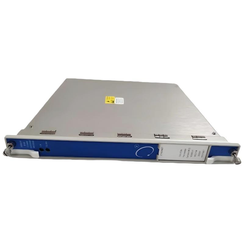
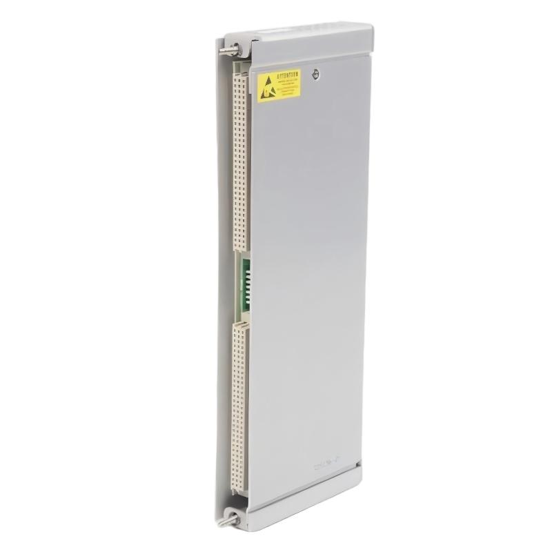
- Bently Nevada
- 3500/91-01-02-00
- Communication Gateway Module
- USA
- 241.3 × 24.4 × 241.8 mm
- 0.79kg
- Xiamen, China
- New & In Stock
- T/T, PayPal, Western Union
- 1 Year
- 1-3 Working Days
- DHL, UPS, TNT, FedEx and EMS.
- 24-Hour Service
- COO
- 2
Our advantage

Global Logistics
We have a 10-year logistics and express cooperation agreement, so our products can be shipped to any place in the world.

Brand new and original
Our products are imported in bulk from the place of origin. Because of the cooperative relationship, our products are all original and 100% new.

24-hour service
We provide 7*24 hours service to our customers. We will be there whenever you need us.

Price advantage
All our products are priced very favorably because we have our own warehouse and supply.
| Company Information | |||
| [email protected] | |||
| Mobile | +8615980777398 | ||
| +8615980777398 | |||
| 15980777398 |
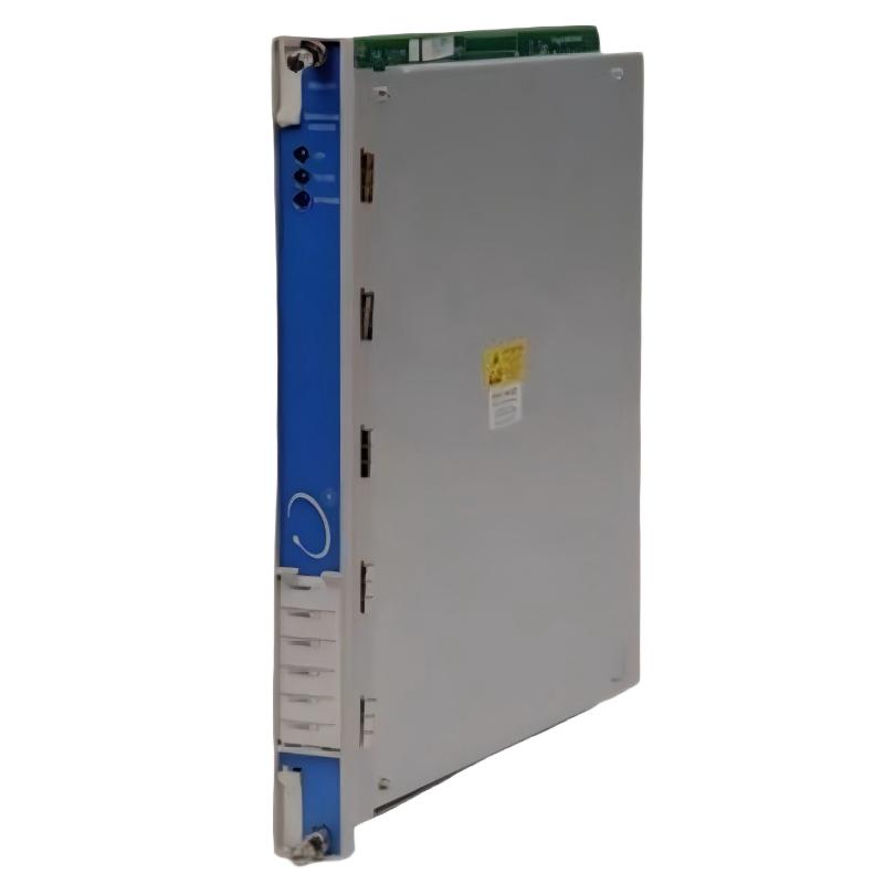
Bently Nevada 3500/91-01-02-00: Product Specifications, Introduction, Applications, Advantages, and Related Models
1. Product Overview
The Bently Nevada 3500/91-01-02-00 is a model designation associated with the 3500 series of industrial machinery monitoring and protection equipment. The 3500 platform is designed for industrial facilities that require continuous monitoring of critical machinery, reliable access to equipment operating information, and integration with plant automation systems.
The 3500 series uses a modular rack architecture. Individual modules perform specific functions, such as processing vibration measurements, monitoring shaft position, receiving speed-reference signals, providing relay outputs, supplying power, and transferring monitoring data to external systems.
The 3500/91 family is associated with communication gateway functionality. In a compatible installation, a gateway can make supported machinery monitoring information available to other industrial systems, helping operators review machine status and coordinate maintenance activities.
Model identification note: The exact configuration represented by 3500/91-01-02-00 cannot be conclusively established from the ordering code alone in this offline response. The suffix may identify configuration-specific options, but its precise meaning should not be inferred without the applicable product documentation. The specifications below distinguish general 3500/91 family characteristics from details that require confirmation for this exact ordering code.
2. Detailed Technical Parameters
The following table provides the key specifications for the 3500/91-01-02-00 configuration, including its fiber-optic communication interface.
| Parameter | Specification |
|---|---|
| Model | 3500/91-01-02-00 |
| Brand | Bently Nevada |
| Product series | 3500 Machinery Protection System |
| Product category | Industrial communication gateway |
| Product type | Ethernet Global Data (EGD) Communication Gateway |
| Primary function | Transfers supported machinery monitoring information to compatible external systems |
| Communication protocol | Ethernet Global Data (EGD) |
| Network transport | UDP/IP for the applicable EGD communication implementation |
| Ethernet interface | 100BASE-FX fiber-optic Ethernet |
| Fiber connector | MT-RJ |
| Physical network medium | Optical fiber |
| Nominal network speed | 100 Mbps |
| Copper Ethernet interface | Not the interface identified by this fiber-optic ordering configuration |
| Typical power consumption | Approximately 7.4 W |
| Main module dimensions (H × W × D) | 241.3 × 24.4 × 241.8 mm |
| Main module weight (kg) | Approximately 0.79 kg |
| I/O module dimensions (H × W × D) | 241.3 × 24.4 × 99.1 mm |
| I/O module weight (kg) | Approximately 0.39 kg |
| Front rack space | One full-height front slot |
| Rear rack space | One full-height rear slot for the associated I/O module |
| Installation method | Compatible 3500 rack |
| Operating temperature | Approximately -30°C to +65°C for the applicable base configuration |
| Storage temperature | Approximately -40°C to +85°C for the applicable base configuration |
| Relative humidity | Up to 95%, non-condensing, subject to the applicable specification |
| Approval option | 00; exact certification status should be checked against the ordering documentation |
| Typical receiving systems | Compatible industrial control, supervisory monitoring, and data acquisition systems |
| Configuration requirements | Compatible rack, I/O assembly, firmware, network settings, and receiving-system configuration |
The values above describe the identified model configuration at a preliminary engineering level. Final installation and purchasing decisions should be based on the technical documentation for the precise hardware revision.
2.1 Fiber-Optic Communication Interface
The -02 interface configuration is associated with 100BASE-FX fiber-optic Ethernet and an MT-RJ connector.
Unlike conventional copper Ethernet, a fiber-optic connection transmits information using optical signals. This provides electrical isolation between connected equipment and can help reduce susceptibility to electromagnetic interference affecting the communication path.
Fiber-optic communication is particularly useful in industrial facilities where monitoring equipment is installed near large motors, generators, variable-frequency drives, or other sources of electrical noise.
The optical fiber type, supported transmission distance, connector condition, and compatibility with the receiving network equipment must be confirmed during installation. The interface should not be assumed to support every type of fiber cable or optical transceiver.
2.2 Main Module Dimensions and Weight
The main module’s reference dimensions are 241.3 mm high, 24.4 mm wide, and 241.8 mm deep.
Its narrow width is consistent with the modular 3500 rack architecture. The module occupies a designated full-height front position, while the associated I/O assembly occupies the appropriate rear position.
The approximate main-module weight is 0.79 kg. This figure should be recorded separately from the weight of the rear I/O module, installation accessories, and shipping packaging.
2.3 I/O Module Dimensions and Weight
The associated I/O module has reference dimensions of 241.3 × 24.4 × 99.1 mm and an approximate weight of 0.39 kg.
The rear I/O assembly provides the physical interface required by the selected configuration. For the model discussed here, particular attention should be paid to the optical connector and the space needed to route and protect the fiber cable.
2.4 Environmental and Power Requirements
The applicable base configuration is associated with a typical power consumption of approximately 7.4 W.
The operating temperature range is approximately -30°C to +65°C, with a storage temperature range of approximately -40°C to +85°C. The exact environmental limits should be confirmed for the installed hardware revision and any applicable certification requirements.
The module should be installed in a compatible rack with the required grounding, environmental protection, and system configuration. Fiber-optic isolation does not eliminate the need for correct rack installation and electrical safety practices.
3. Product Introduction
3.1 What Is the 3500/91-01-02-00?
The Bently Nevada 3500/91-01-02-00 is an Ethernet Global Data communication gateway associated with the 3500 machinery monitoring platform. Its distinguishing feature is the fiber-optic Ethernet interface, which allows supported monitoring information to be exchanged with compatible external equipment.
The module is designed to operate as part of a larger machinery monitoring installation rather than as a standalone measurement instrument.
In a typical industrial system, sensors measure physical conditions such as shaft displacement, vibration, speed, or temperature. Compatible monitoring modules process these signals and make the resulting information available within the rack. The communication gateway then transfers supported information to an external system for display, recording, alarm management, or further processing.
This arrangement allows machinery monitoring information to become part of a wider industrial automation environment.
3.2 Main Functions
Communication between monitoring and control systems
The gateway provides a communication interface between compatible 3500 rack equipment and external systems. Supported information can be made available to the receiving system according to the configured EGD communication arrangement.
Fiber-optic data transmission
The 100BASE-FX interface provides optical Ethernet communication. Fiber is particularly useful when the installation requires electrical isolation between network segments or needs to reduce the effect of electromagnetic interference on the communication link.
Centralized equipment information
When properly configured, the gateway can help deliver supported machinery values and status information to centralized monitoring or control applications.
Industrial network integration
The module can form part of an industrial communication architecture where machinery condition information is integrated with process data and other equipment status information.
Support for equipment maintenance
The gateway can help make available information easier for authorized maintenance personnel to access. The actual diagnostic information depends on the sensors, monitoring modules, and software installed in the complete system.
3.3 Position Within the 3500 Series
The 3500 series is a modular machinery monitoring and protection platform. Its modules perform different functions, and the gateway occupies the communication portion of that architecture.
The distinction is important: the 3500/91 transfers supported information, while measurement modules acquire and process particular machinery signals. Relay modules provide configured output functions, and power supplies provide power to compatible rack components.
The gateway therefore complements the other modules instead of replacing them.
4. Product Applications
4.1 Power Generation
Power stations depend on the reliable operation of turbines, generators, pumps, and auxiliary machinery.
A compatible fiber-optic gateway can help integrate supported machinery monitoring information into a plant’s control or supervisory environment.
Typical applications include centralized visibility of equipment status, communication of selected monitoring values, maintenance investigation following abnormal conditions, and integration of machinery information with plant operating data.
4.2 Oil and Gas Industry
Oil and gas facilities operate critical rotating equipment such as gas compressors, pumps, turbines, and other high-value assets.
In these environments, the gateway can support communication between a machinery monitoring rack and compatible external automation systems. The fiber interface can be beneficial where electrical noise or isolation between connected systems is an important design consideration.
4.3 Petrochemical and Chemical Processing
Petrochemical plants frequently operate machinery continuously under demanding process conditions.
The gateway can help transfer supported monitoring information to a centralized operating environment, making it easier for personnel to review equipment status and coordinate maintenance activities.
4.4 Compressor Stations
Compressor stations require reliable monitoring because an unexpected shutdown may interrupt production or transportation processes.
A gateway can help make supported compressor monitoring information available to a compatible supervisory system. The specific information available depends on the installed monitoring modules and communication configuration.
4.5 Pumping Stations and Utility Facilities
Water treatment facilities, utility plants, and industrial pumping stations use pumps, motors, and other rotating equipment that require reliable operation.
Where a compatible 3500 monitoring system is installed, the gateway can support centralized access to selected machinery information.
4.6 Industrial Manufacturing
Manufacturing plants often operate large numbers of motors, fans, pumps, and other mechanical assets.
The gateway can help connect machinery monitoring information with the plant’s wider automation architecture, allowing maintenance personnel to review supported equipment information without relying exclusively on local rack access.
4.7 Existing Monitoring System Upgrades
The module may also be considered during a communication upgrade or replacement project involving an existing 3500 installation.
For these projects, the optical interface is a particularly important selection criterion. A replacement must support the required network medium, connector, protocol, rack configuration, and software environment.
A module with a copper Ethernet interface should not be assumed to be interchangeable with the fiber-optic configuration simply because the model family is similar.
5. Product Advantages
5.1 Fiber-Optic Electrical Isolation
The optical communication path does not conduct electrical current between the connected network endpoints in the way a copper Ethernet connection does.
This can help reduce problems associated with ground-potential differences and electrical interference along the communication link. It does not eliminate the need for appropriate grounding and protection of the monitoring rack itself.
5.2 Reduced Susceptibility to Electromagnetic Interference
Industrial environments often contain motors, drives, generators, switching equipment, and other sources of electromagnetic noise.
Fiber-optic communication is inherently resistant to electromagnetic interference affecting the optical link. This can improve the suitability of the communication path in electrically demanding environments.
5.3 High-Speed Data Communication
The 100BASE-FX interface provides a nominal data rate of 100 Mbps.
This allows the configured gateway to communicate supported information over an Ethernet network. Actual data availability and update behavior depend on the gateway configuration, network architecture, and receiving system.
5.4 Integration With the 3500 Platform
The gateway is designed for use within the compatible 3500 machinery monitoring architecture.
It can support integration of machinery monitoring information without requiring the gateway itself to perform every measurement or protection function.
5.5 Centralized Monitoring
When the receiving system is configured correctly, supported machinery information can be presented alongside other plant information.
This can improve visibility for operators and maintenance personnel, particularly in installations with numerous machines distributed across multiple operating areas.
5.6 Modular Replacement
The rack-based form factor supports a structured installation approach. When the correct replacement configuration is selected, the modular architecture can simplify maintenance compared with replacing an entire monitoring system.
However, the rack interface, I/O assembly, firmware, and configuration must be compatible.
5.7 Support for Maintenance Workflows
Access to supported equipment information can help maintenance teams investigate abnormal conditions, review equipment status, and coordinate inspections.
The gateway does not independently guarantee predictive maintenance or fault diagnosis. These outcomes depend on the quality of the underlying measurements and the procedures used to interpret them.
5.8 Important Limitations
The gateway is not a standalone vibration monitor, temperature monitor, or independent machinery protection system.
Its role is to communicate supported information. Protection performance depends on the complete installed system, including the appropriate measurement modules, sensors, configured logic, and other required components.
6. Five Related Models in the Same Series or Functional Group
The following five models are useful candidates when comparing communication, data access, speed-reference, and relay-output functions within the 3500 platform.
The dimensional and weight figures are preliminary reference values. They are not guaranteed specifications for every hardware revision or complete assembly.
| Model | Product type | Main technical parameters | Dimensions (H × W × D) | Weight (kg) |
|---|---|---|---|---|
| 3500/92 | Communication gateway | Supports communication of selected rack information; interface and protocols depend on configuration | Approx. 241.3 × 24.4 × 241.8 mm, main module | Approx. 0.82 |
| 3500/22M | Transient Data Interface | Rack data interface; supports compatible data access and configuration functions | Approx. 241.3 × 24.4 × 241.8 mm | Approx. 0.8–0.9 |
| 3500/25 | Enhanced Keyphasor module | Speed and phase-reference signal functions for compatible monitoring applications | Approx. 241.3 × 24.4 × 241.8 mm | Approx. 0.8–0.9 |
| 3500/32M | Four-channel relay module | Four configured relay channels for supported alarm and status output applications | Approx. 241.3 × 24.4 × 241.8 mm | Approx. 0.6–0.9 |
| 3500/33 | Sixteen-channel relay module | Sixteen relay channels for configured alarm and status outputs | Approx. 241.3 × 24.4 × 241.8 mm | Approx. 0.7 |
For the relay modules, the main module and rear I/O module have separate dimensions and weights. Confirm the exact assembly before mechanical planning.
6.1 3500/92 Communication Gateway
The 3500/92 is a relevant comparison when the primary requirement is communication between a monitoring rack and external industrial systems.
Its interface and protocol options differ according to configuration. It should be evaluated against the required network interface and receiving-system requirements rather than treated as a direct replacement for the fiber-optic 3500/91-01-02-00.
6.2 3500/22M Transient Data Interface
The 3500/22M provides rack-level data interface functionality.
It is useful to consider when a project requires supported rack communication, data access, or configuration functions. Its role differs from that of a communication gateway, so selection should be based on the intended system architecture.
6.3 3500/25 Enhanced Keyphasor Module
The 3500/25 supports speed and phase-reference signal functions.
It may be required in installations where rotational-speed information or a phase reference is used by compatible machinery monitoring modules.
It is a complementary measurement-support module, not a general-purpose Ethernet gateway.
6.4 3500/32M Four-Channel Relay Module
The 3500/32M provides four relay channels for configured applications.
It may be appropriate where a system needs a limited number of relay outputs for alarm indication or other supported external interfaces.
The required relay logic and electrical interface should be checked before selecting the module.
6.5 3500/33 Sixteen-Channel Relay Module
The 3500/33 provides sixteen relay channels and can be useful when more relay outputs are required.
Its function differs from that of the 3500/91 because it focuses on relay output rather than communication of monitoring data over a network.
7. Five Additional Bently Nevada Models for Industrial Applications
The following models cover other common functional categories in machinery monitoring and protection. They are complementary options rather than direct replacements for the fiber-optic gateway.
| Model | Product name | Main technical parameters | Dimensions (H × W × D) | Weight (kg) |
|---|---|---|---|---|
| 3500/42M | Proximitor / Seismic Monitor | Four-channel monitoring platform; supported measurement functions depend on channel configuration | Approx. 241.3 × 24.4 × 241.8 mm | Approx. 0.91 |
| 3500/40M | Proximitor Monitor | Four-channel proximity monitoring; compatible displacement measurement functions | Approx. 241.3 × 24.4 × 241.8 mm | Approx. 0.91 |
| 3500/15 | Power Supply Module | Rack power supply; AC and DC variants available, with ratings depending on configuration | Approx. 120.7 × 50.8 × 251.5 mm | Approx. 1.39 |
| 3500/65 | Temperature Monitor | Temperature monitoring through compatible sensor and I/O arrangements | Approx. 241.3 × 24.4 × 241.8 mm | Approx. 0.91 |
| 3500/72M | Reciprocating Rod Position Monitor | Monitoring of supported reciprocating machinery rod-position parameters | Approx. 241.3 × 24.4 × 241.8 mm | Approx. 0.91 |
The 3500/15 uses a different physical form factor from full-height monitoring modules. The listed dimensions and weights are preliminary references and should be checked against the specific version.
7.1 3500/42M Proximitor / Seismic Monitor
The 3500/42M is designed for compatible machinery measurement and monitoring applications involving vibration and displacement.
It can help provide information about the operating condition of monitored machinery when used with the appropriate transducers and configuration.
This module performs measurement-related functions, unlike the 3500/91 communication gateway.
7.2 3500/40M Proximitor Monitor
The 3500/40M is associated with proximity-based machinery monitoring.
It is relevant to applications where compatible displacement measurements are required to evaluate shaft movement or other monitored mechanical conditions.
Selection should consider the sensor type, channel requirements, monitoring configuration, and compatibility with the existing system.
7.3 3500/15 Power Supply Module
The 3500/15 provides power to compatible 3500 rack components.
It is important to match the input supply type, applicable ratings, redundancy arrangement, and hardware configuration when replacing a power supply.
The 3500/15 is not an alternative to the 3500/91 gateway, but it is an essential supporting component in a properly configured rack.
7.4 3500/65 Temperature Monitor
The 3500/65 provides temperature monitoring functions through compatible sensor and I/O arrangements.
Temperature information can help maintenance personnel evaluate the condition of bearings, process equipment, and other monitored locations.
The precise channel configuration and supported sensor types must be checked for the selected version.
7.5 3500/72M Reciprocating Rod Position Monitor
The 3500/72M is designed for compatible reciprocating machinery monitoring applications.
Rod-position information is important in some reciprocating compressor applications because mechanical movement must be evaluated against the equipment’s operating requirements.
This is a specialized monitoring module and should not be considered interchangeable with a communication gateway.
8. Consolidated Comparison of the Ten Models
| Model | Functional category | Primary application | Relationship to 3500/91-01-02-00 |
|---|---|---|---|
| 3500/92 | Communication gateway | Monitoring data communication | Closest functional comparison |
| 3500/22M | Rack data interface | Rack communication and supported data access | Complementary interface |
| 3500/25 | Speed and phase reference | Keyphasor-related monitoring | Complementary measurement module |
| 3500/32M | Relay output | Configured alarm and status outputs | Complementary output module |
| 3500/33 | Relay output | Multiple configured relay outputs | Complementary output module |
| 3500/42M | Vibration and displacement monitoring | Machinery condition monitoring | Complementary monitor |
| 3500/40M | Proximity monitoring | Compatible shaft displacement measurements | Complementary monitor |
| 3500/15 | Power supply | Power for compatible rack components | Supporting hardware |
| 3500/65 | Temperature monitoring | Compatible temperature measurement | Complementary monitor |
| 3500/72M | Reciprocating machinery monitoring | Rod-position monitoring | Specialized monitor |
9. Installation and Procurement Considerations
9.1 Confirm the Complete Ordering Code
The complete part number should be matched against the installed module and the applicable configuration documentation.
For this model, the -02 interface option is especially important because the fiber-optic connection differs physically and electrically from a copper Ethernet connection.
9.2 Check the Fiber-Optic Network
Before ordering, confirm the following:
-
Whether the receiving equipment supports the required 100BASE-FX interface.
-
Whether the optical connector is compatible with the installed cable.
-
Whether the fiber type and transmission distance meet the installation requirements.
-
Whether the network configuration supports the required EGD communication.
-
Whether the receiving system can process the information provided by the gateway.
9.3 Check the Rack and Software Configuration
The module must be compatible with the installed rack, associated I/O assembly, firmware, and configuration software.
A physically compatible module may still be unsuitable if it uses a different communication interface or configuration.
9.4 Confirm Dimensions and Weight
For mechanical planning, use the main module and I/O module dimensions separately.
The approximate main-module weight of 0.79 kg and I/O-module weight of 0.39 kg are useful preliminary references. They should not automatically be treated as the weight of a complete packaged assembly.
9.5 Protect the Fiber Connection
Fiber connectors require appropriate handling and cleanliness.
During installation, use compatible cleaning procedures, avoid sharp cable bends, protect the connector from contamination, and observe the cable manufacturer’s bend-radius requirements.
A clean, correctly connected optical path helps reduce the risk of communication problems.
9.6 Check Environmental and Approval Requirements
Confirm the temperature, humidity, and installation requirements for the precise hardware revision.
The -00 approval option should also be checked against the certification requirements of the intended installation. Do not assume that the configuration carries a particular hazardous-area certification merely because other modules in the series may have one.
10. Final Product Summary
The Bently Nevada 3500/91-01-02-00 is associated with the 3500 machinery monitoring platform and is identified as an Ethernet Global Data communication gateway with a 100BASE-FX fiber-optic interface and MT-RJ connector.
Its primary purpose is to transfer supported machinery monitoring information to compatible external systems. Its fiber-optic interface can be advantageous in industrial environments where electrical isolation and resistance to electromagnetic interference are important.
The principal technical reference values for the identified configuration are:
-
Main module dimensions: approximately 241.3 × 24.4 × 241.8 mm.
-
Main module weight: approximately 0.79 kg.
-
I/O module dimensions: approximately 241.3 × 24.4 × 99.1 mm.
-
I/O module weight: approximately 0.39 kg.
-
Typical power consumption: approximately 7.4 W.
-
Ethernet interface: 100BASE-FX fiber optic.
-
Connector: MT-RJ.
-
Nominal network speed: 100 Mbps.
The five related models recommended for comparison are the 3500/92, 3500/22M, 3500/25, 3500/32M, and 3500/33. Five additional models covering other industrial monitoring functions are the 3500/42M, 3500/40M, 3500/15, 3500/65, and 3500/72M.
For purchasing and replacement, the most important point is to verify the exact ordering code, fiber interface, I/O configuration, rack compatibility, and applicable environmental and approval requirements. This ensures that the selected module matches the intended industrial installation rather than merely sharing the same product family.