

ProductPRODUCT
Featured products
Contact Us
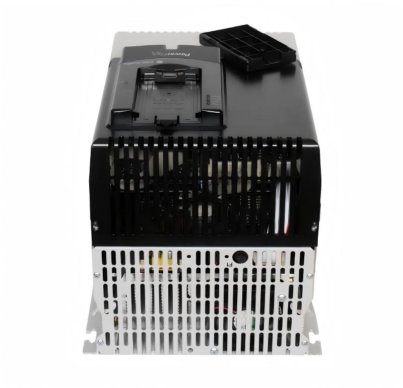
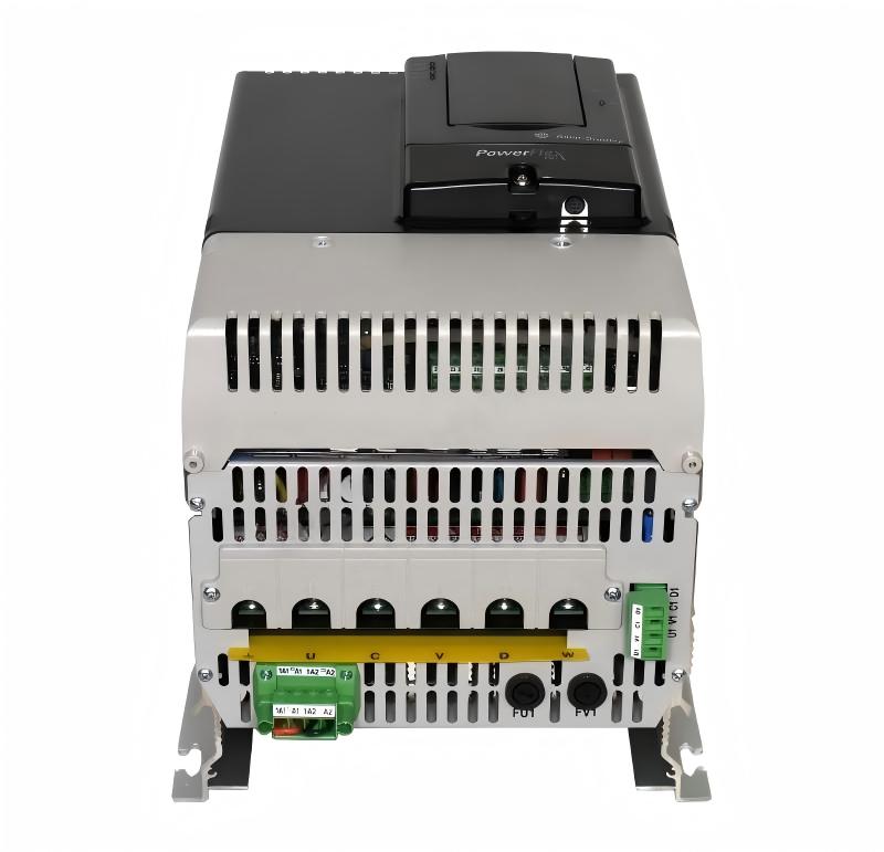
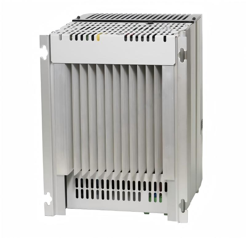
- Allen Bradley
- 20J1F4F650JNDNNNNN
- PowerFlex AC Drive
- USA
- 1,000–1,500 × 800–1,100 × 2,000–2,400 mm
- 1100kg
- Xiamen, China
- New & In Stock
- T/T, PayPal, Western Union
- 1 Year
- 1-3 Working Days
- DHL, UPS, TNT, FedEx and EMS.
- 24-Hour Service
- COO
- 3
Our advantage

Global Logistics
We have a 10-year logistics and express cooperation agreement, so our products can be shipped to any place in the world.

Brand new and original
Our products are imported in bulk from the place of origin. Because of the cooperative relationship, our products are all original and 100% new.

24-hour service
We provide 7*24 hours service to our customers. We will be there whenever you need us.

Price advantage
All our products are priced very favorably because we have our own warehouse and supply.
| Company Information | |||
| [email protected] | |||
| Mobile | +8615980777398 | ||
| +8615980777398 | |||
| 15980777398 |
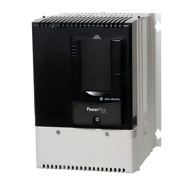
Allen-Bradley 20J1F4F650JNDNNNNN — Detailed Product Specifications, Applications, Advantages and Related Models
1. Product Overview
The 20J1F4F650JNDNNNNN is a high-power industrial regenerative bus supply designed for large variable-speed drive systems, common DC bus installations, and applications where controlled energy recovery is required.
It belongs to the PowerFlex 750 Bus Supplies product family and is part of the high-power PowerFlex drive architecture.
The unit uses an Active Front End (AFE) regenerative input arrangement. This allows the system to control the transfer of electrical energy between the incoming AC power system and the common DC bus.
The product is intended for demanding industrial environments where conventional individual drive front ends may not provide the required level of regenerative capability, power management, or system integration.
The model is specified for 690 VAC three-phase operation and has a current rating in the approximately 650–667 A class, depending on the applicable rating condition.
The unit is air cooled, floor mounted, and intended for large industrial installations.
Its basic design is particularly suitable for machinery containing several large drives that need to operate from a common DC bus.
2. Brand and Product Series
| Item | Specification |
|---|---|
| Brand | Allen-Bradley |
| Product Family | PowerFlex 750 Bus Supplies |
| Product Series | PowerFlex 755T / PowerFlex 755TM architecture |
| Model | 20J1F4F650JNDNNNNN |
| Product Type | Regenerative Low-Harmonic Bus Supply |
| Input Technology | Active Front End |
| Cooling Method | Air Cooled |
| Installation | Floor Mounted |
| Input Voltage | 690 VAC |
| Input Phase | Three Phase |
| Current Class | Approx. 650–667 A |
| Dynamic Braking | None |
| Main Function | AC-to-DC regenerative bus supply |
| System Architecture | Common DC Bus |
| Enclosure Class | Industrial cabinet / Type 1-IP21 class configuration |
| Intended Application | High-Power Multi-Drive Systems |
The PowerFlex 755T architecture is intended for applications that require advanced control of electrical power, regeneration, harmonic management and coordinated multi-drive operation.
The 20J1F4F650JNDNNNNN is therefore better understood as a large system-level power-conversion unit rather than as a small standalone motor inverter.
3. Main Technical Parameters
| Parameter | 20J1F4F650JNDNNNNN |
|---|---|
| Model | 20J1F4F650JNDNNNNN |
| Brand | Allen-Bradley |
| Product Family | PowerFlex 750 Bus Supplies |
| Series | PowerFlex 755T |
| Platform | PowerFlex 755TM |
| Product Type | Air-Cooled Regenerative Bus Supply |
| Input Type | AFE Regenerative |
| Input Voltage | 690 VAC |
| Input Phase | Three Phase |
| Rated Current | Approx. 650 A |
| Alternate Current Rating | Approx. 667 A |
| Dynamic Braking | None |
| Regenerative Operation | Yes |
| Harmonic Reduction | Low-Harmonic AFE Architecture |
| Common DC Bus | Yes |
| Cooling | Air Cooled |
| Mounting | Floor Mount |
| Enclosure | Type 1 / IP21 class |
| Duty | High-Power Industrial Duty |
| Approx. Dimensions | 1,000–1,500 W × 800–1,100 D × 2,000–2,400 H mm* |
| Approx. Weight | 700–1,100 kg* |
* The exact mechanical dimensions and shipping weight depend on the cabinet arrangement, options, accessories, power connections and configured installation package. The values above are practical planning estimates rather than guaranteed factory dimensions.
For final mechanical design, lifting calculations, foundation loading and installation clearance, the actual configured equipment drawing should always be used.
4. Product Identification
The 20J1F4F650JNDNNNNN catalog number identifies a specific high-power configuration within the PowerFlex 750 Bus Supplies family.
The important characteristics of this configuration are its F-series high-voltage arrangement, 650 A class current capacity, 690 VAC input and regenerative AFE architecture.
The product is designed to operate as the front-end section of a larger drive system.
This means that the unit does not have to be treated as an isolated motor drive.
Instead, it can be integrated with several drive inverter sections connected to a shared DC bus.
That architecture is particularly useful in large machines where multiple motors operate together.
5. Product Introduction
The 20J1F4F650JNDNNNNN is a large industrial bus supply designed to convert incoming AC electrical power into controlled DC bus power while also allowing regenerative energy to flow back toward the AC supply.
This two-way energy capability is one of the main differences between a regenerative AFE system and a traditional passive rectifier.
During normal motoring operation, electrical energy flows from the AC supply into the drive system.
The AFE converts and controls that power for use by the connected drive inverter sections.
During braking or overhauling conditions, the motor can operate as a generator.
The generated energy flows back into the DC bus.
The regenerative front end can then transfer that energy back into the AC electrical system.
This provides a practical solution for large machines with repeated acceleration and deceleration.
6. Active Front End Technology
The Active Front End is a key feature of the 20J1F4F650JNDNNNNN.
A conventional rectifier primarily converts AC voltage into DC voltage.
An AFE goes further by actively controlling the current flowing between the AC source and the DC bus.
This gives the system significantly more control over power flow.
The AFE can operate in both directions.
During normal operation:
AC Supply → AFE → DC Bus → Drive Inverters → Motors
During regeneration:
Motors → Drive Inverters → DC Bus → AFE → AC Supply
This bidirectional energy path is particularly valuable in high-inertia industrial machinery.
7. Regenerative Operation
Regeneration is one of the most important reasons to use the 20J1F4F650JNDNNNNN.
When a large motor decelerates, the rotating mechanical system still contains kinetic energy.
Instead of allowing this energy to increase the DC bus voltage uncontrollably, the drive system can transfer the energy through the regenerative front end.
The AFE returns the energy to the AC power network.
This can substantially reduce the amount of energy that would otherwise need to be converted into heat through braking resistors.
The effect is especially noticeable in applications with frequent braking cycles.
Examples include:
- Cranes
- Hoists
- Elevators
- Large conveyors
- Test stands
- Winders
- Unwinders
- Rolling equipment
- High-inertia production machinery
- Material handling systems
- Large process machinery
8. Low-Harmonic Operation
Large variable-frequency drive systems can introduce harmonic currents into the electrical distribution network.
The problem becomes more important as the installed drive power increases.
The 20J1F4F650JNDNNNNN uses an active front-end architecture designed for low-harmonic operation.
The front end actively controls the input current waveform instead of relying only on a simple passive rectifier.
This can reduce harmonic current distortion and improve the electrical characteristics of the overall drive installation.
For large factories with multiple high-power drives, this can be an important part of the electrical system design.
Potential benefits include easier power-quality management and reduced impact on upstream electrical equipment.
Actual harmonic performance depends on the complete installation, operating conditions and system design.
9. High-Current Capability
The 20J1F4F650JNDNNNNN is a high-current industrial power-conversion unit.
The catalog information identifies the product in the 650 A class, with an additional current value of approximately 667 A associated with its rating information.
At a 690 VAC three-phase supply level, this represents a substantial industrial power system.
A simplified three-phase apparent-power calculation illustrates the scale:
S ≈ √3 × V × I
Using 690 VAC and 650 A gives approximately:
S ≈ 1.732 × 690 × 650
S ≈ 777 kVA
This is an apparent-power reference rather than a direct statement of motor shaft power.
Actual usable power depends on power factor, efficiency, duty rating, operating conditions and the complete drive configuration.
10. Common DC Bus Architecture
The common DC bus is one of the major reasons for using a dedicated bus supply.
In a conventional multi-drive system, each drive may have its own AC input section.
With a common DC bus architecture, a centralized bus supply can provide DC power to multiple inverter sections.
A simplified structure is:
AC Power
↓
20J1F4F650JNDNNNNN AFE Bus Supply
↓
Common DC Bus
↓
Multiple Drive Inverter Sections
↓
Multiple Motors
This architecture is particularly useful for machines where several motors work together as one coordinated production system.
11. Energy Sharing Between Drives
One of the practical advantages of a common DC bus is the ability to share energy between connected drives.
For example, one motor may be accelerating while another motor is braking.
The braking motor generates electrical energy.
That energy enters the common DC bus.
Another drive can consume part of that energy while accelerating its motor.
This means that energy can be reused inside the machine instead of immediately being dissipated.
If there is more regenerated energy than the connected drives can consume, the regenerative AFE can provide a controlled path back to the AC supply.
This creates a more flexible energy-management system.
12. Main Product Applications
12.1 Large Conveyors
Large conveyor systems often contain several motors.
Some sections may accelerate while other sections maintain speed.
During controlled stopping, the inertia of the conveyor can cause the motors to regenerate.
The 20J1F4F650JNDNNNNN can be integrated into such a system to manage both motoring and regenerative power flow.
This makes it suitable for large mining conveyors, bulk-material handling systems and major production lines.
12.2 Cranes and Hoists
Cranes are a classic regenerative application.
A lifting motor consumes energy while raising a load.
When the load is lowered, gravity drives the mechanical system and the motor can return energy to the electrical system.
A regenerative AFE can manage this energy more effectively than a system that relies entirely on braking resistors.
12.3 Elevators
Large industrial elevators and vertical lifting equipment can experience significant regeneration.
The energy generated during lowering or braking can be transferred through the DC bus and returned to the AC supply.
This makes regenerative drive architecture useful for high-cycle vertical transportation systems.
12.4 Steel and Metal Processing
Steel mills and metal-processing lines often contain several high-power motors.
Rolling equipment, tension systems and material-handling sections can have rapidly changing speed and torque requirements.
A common DC bus can help coordinate these drives.
The regenerative capability can also handle energy generated during rapid deceleration.
12.5 Paper and Pulp Machinery
Paper machines frequently use many coordinated motors.
Speed matching and tension control are critical.
Certain sections may continuously accelerate and decelerate relative to others.
The common DC bus architecture can help manage energy exchange between drive sections.
12.6 Mining Equipment
Mining operations use large electrical motors for conveyors, crushers, hoists and processing equipment.
These systems can involve very high mechanical inertia.
The 20J1F4F650JNDNNNNN is suitable for large-scale drive architectures where a regenerative common DC bus is required.
12.7 Cement Plants
Cement production involves large fans, mills, conveyors, crushers and material-handling equipment.
High-power drive systems can benefit from centralized power conversion.
The common DC bus architecture can also be useful where several large motors operate as part of the same process.
12.8 Test Stands and Dynamometers
Test stands can repeatedly accelerate and decelerate large motors.
The amount of regenerative energy can become substantial during repeated testing.
A regenerative front end allows this energy to be returned to the electrical system rather than continuously dissipated as heat.
12.9 Large Process Machinery
Chemical, petrochemical, food-processing and other continuous-process industries can use multiple large motors.
Where coordinated speed control and regenerative energy management are required, a common DC bus architecture can provide a practical solution.
13. Main Product Advantages
13.1 Regenerative Energy Recovery
The product can return regenerated energy to the AC supply.
This is one of its most important advantages for high-inertia machinery.
It avoids making braking resistors the primary method of dealing with large amounts of regenerative energy.
13.2 Reduced Braking Heat
Traditional braking resistors convert electrical energy into heat.
In a heavily regenerative application, this can create a significant thermal load.
A regenerative AFE can send energy back to the electrical system instead.
This can reduce the amount of heat generated by braking.
13.3 Low-Harmonic Architecture
The active front end provides controlled input current characteristics.
This can reduce harmonic distortion compared with conventional passive rectification.
This is especially useful in facilities with large installed drive capacity.
13.4 Common DC Bus
Multiple inverter sections can share the same DC power source.
This allows the drive system to be designed around a centralized front end.
For large machinery, this can simplify the overall electrical architecture.
13.5 Energy Sharing
Energy generated by one drive can potentially be used by another connected drive.
This is a useful feature in machines with different acceleration and deceleration cycles.
13.6 High-Power Industrial Capability
The 650 A class current rating makes the product suitable for large industrial equipment.
It is intended for applications far beyond the power range of compact machine drives.
13.7 Centralized Power Management
Instead of every inverter section operating with an independent AC front end, the common bus arrangement provides a centralized power-conversion point.
This can be useful for large machine builders and system integrators.
14. Mechanical Characteristics
The 20J1F4F650JNDNNNNN is not a compact panel-mounted drive.
It is a large floor-mounted industrial power-conversion system.
The cabinet requires suitable installation space, service access and cooling airflow.
Because the unit is air cooled, the surrounding environment must allow adequate heat removal.
The installation should provide sufficient space around the cabinet for inspection, maintenance, cable routing and ventilation.
15. Approximate Dimensions and Weight
Exact dimensions for a configured PowerFlex 750 Bus Supply can vary according to cabinet arrangement and installed options.
For preliminary engineering purposes, the 20J1F4F650JNDNNNNN can be treated as a large industrial cabinet with approximately the following mechanical envelope.
| Mechanical Parameter | Approximate Value |
|---|---|
| Width | Approx. 1,000–1,500 mm |
| Depth | Approx. 800–1,100 mm |
| Height | Approx. 2,000–2,400 mm |
| Weight | Approx. 700–1,100 kg |
| Mounting | Floor Mount |
| Cooling | Air Cooled |
| Enclosure Class | Type 1 / IP21 class |
| Installation Environment | Controlled Industrial Area |
| Service Access | Required |
| Lifting Equipment | Normally Required for Handling |
The dimensions and weight should be regarded as approximate planning values.
A high-power bus supply can change considerably in physical size depending on cabinet configuration, disconnect equipment, bus arrangements, options and other accessories.
For a final installation, the actual configured mechanical drawing should be used.
16. Electrical Installation Considerations
The 20J1F4F650JNDNNNNN operates at the 690 VAC class and therefore requires a properly designed high-voltage industrial electrical system.
The upstream transformer and switchgear should be selected according to the complete load profile.
Protective devices must be coordinated with the available fault current and the applicable electrical standards.
Power cables must be correctly sized for the actual operating current, installation method and environmental conditions.
The DC bus connections also require careful consideration because high-energy DC systems can remain hazardous after the incoming AC source has been disconnected.
Proper isolation, lockout procedures and discharge verification are important before maintenance.
17. Cooling and Thermal Management
The product is air cooled.
This means that heat generated by the power electronics must be transferred into the surrounding environment.
The installation area should therefore provide suitable ventilation.
Blocked air passages can increase internal temperature and reduce equipment reliability.
Dust, oil mist and other contaminants can also affect cooling performance.
For harsh industrial environments, the enclosure arrangement and environmental conditions should be considered carefully before installation.
18. Maintenance Considerations
Routine maintenance should include inspection of cooling components, electrical connections and cabinet ventilation.
Cooling fans should be kept in good operating condition.
Air passages should remain clean and unobstructed.
Electrical connections should be inspected for signs of overheating, discoloration, mechanical looseness or abnormal wear.
The DC bus should always be treated as a high-energy electrical circuit.
Maintenance personnel should follow the appropriate electrical safety procedures before accessing the equipment.
19. Typical System Architecture
A typical installation can be represented as:
690 VAC Three-Phase Supply
↓
20J1F4F650JNDNNNNN
↓
Active Front End
↓
Common DC Bus
↓
Drive Inverter 1
Drive Inverter 2
Drive Inverter 3
Drive Inverter 4
↓
Multiple Industrial Motors
This architecture is particularly useful for large production machinery with several coordinated axes.
20. Example — Multi-Motor Conveyor
Consider a long conveyor with several drive motors.
During startup, several motors require power simultaneously.
During normal production, each motor contributes a controlled portion of the mechanical load.
During stopping, the conveyor’s inertia causes the motors to regenerate.
The energy generated by the braking motors enters the common DC bus.
The regenerative AFE can then return the excess energy to the AC supply.
This provides a coordinated energy path for the complete conveyor system.
21. Example — Crane System
A crane can have a very different power profile from a conventional conveyor.
When lifting a load, electrical energy is converted into mechanical potential energy.
When lowering the load, the mechanical energy flows in the opposite direction.
The motor can therefore become a generator.
A regenerative front end is well suited to this type of bidirectional energy flow.
The common DC bus can also allow several crane motion systems to share energy where the system architecture permits.
22. Example — Metal Processing Line
A metal-processing line can contain multiple synchronized motors.
One motor may control material speed.
Another may control tension.
A third may drive a processing roll.
Another motor may accelerate or decelerate the material.
Because these motors do not always consume energy at exactly the same time, the common DC bus provides an opportunity for energy sharing.
The 20J1F4F650JNDNNNNN can therefore serve as the centralized front-end power source for a coordinated drive system.
23. Five Related Models from the Same Series
The following models are closely related PowerFlex 750 Bus Supply configurations and can be considered for systems with different current and power requirements.
| Model | Product Family | Cooling | Voltage Class | Current Class | General Application |
|---|---|---|---|---|---|
| 20J1F4F505JNDNNNNN | PowerFlex 750 Bus Supplies | Air Cooled | 690 VAC | Approx. 505 A | High-power regenerative systems |
| 20J1F4F735JNDNNNNN-C1-P50 | PowerFlex 750 Bus Supplies | Air Cooled | 690 VAC class | Approx. 735 A | Higher-power multi-drive systems |
| 20J1F4F920LNDNNNNN | PowerFlex 750 Bus Supplies | Air Cooled | 690 VAC class | Approx. 920 A class | Very high-power applications |
| 20J1F4F1K8JNDNNNNN-C1-P16 | PowerFlex 750 Bus Supplies | Air Cooled | 690 VAC class | Approx. 1.8 kA class | Very large industrial systems |
| 20J1F4F2K3JNDNNNNN-P50 | PowerFlex 750 Bus Supplies | Air Cooled | 690 VAC class | Approx. 2.3 kA class | Extremely high-power drive systems |
These models are useful when selecting a bus supply according to the required system current.
The 20J1F4F505JNDNNNNN represents a lower current configuration.
The 20J1F4F735JNDNNNNN moves into a higher current range.
The 20J1F4F920LNDNNNNN is a larger configuration for applications requiring substantially more power.
The 1.8 kA and 2.3 kA class configurations are intended for very large industrial systems.
24. Related Model Comparison
| Model | Approx. Current Class | Voltage Class | Cooling | Regenerative AFE | Typical Scale |
|---|---|---|---|---|---|
| 20J1F4F505JNDNNNNN | 505 A | 690 VAC | Air Cooled | Yes | High Power |
| 20J1F4F650JNDNNNNN | 650 A | 690 VAC | Air Cooled | Yes | High Power |
| 20J1F4F735JNDNNNNN-C1-P50 | 735 A | 690 VAC class | Air Cooled | Yes | High Power |
| 20J1F4F920LNDNNNNN | 920 A class | 690 VAC class | Air Cooled | Yes | Very High Power |
| 20J1F4F1K8JNDNNNNN-C1-P16 | 1.8 kA class | 690 VAC class | Air Cooled | Yes | Very Large Power |
The selection between these configurations should be based on the actual continuous current, overload requirements, regenerative duty cycle, ambient conditions and system architecture.
25. Five Same-Brand Popular Models
The broader PowerFlex portfolio includes compact, medium-power and high-power variable-frequency drives.
The following models are useful reference points when comparing the 20J1F4F650JNDNNNNN with more conventional drive products.
| Model | Product Family | Typical Voltage Class | General Power Class | Main Application |
|---|---|---|---|---|
| 25B-D017N114 | PowerFlex 525 | 380–480 VAC | Low/Medium | Compact machine automation |
| 20F11NC022JA0NNNNN | PowerFlex 753 | 380–480 VAC class | Medium | General industrial machinery |
| 20F11NC034JA0NNNNN | PowerFlex 753 | 380–480 VAC class | Medium/High | Industrial motor control |
| 20G1ANB140JA0NNNNN | PowerFlex 755 | 380–480 VAC class | High | Advanced industrial drives |
| 20G1ANC350JA0NNNNN | PowerFlex 755 | 380–480 VAC class | High | Large industrial machinery |
These products serve different application ranges.
The PowerFlex 525 family is commonly associated with compact machines.
The PowerFlex 753 family is designed for more demanding industrial motor-control applications.
The PowerFlex 755 family provides advanced control capabilities for larger machinery.
The 20J1F4F650JNDNNNNN is different because it is a dedicated bus-supply product designed around a regenerative common DC bus architecture.
26. Broader Product Comparison
| Product Family | Primary Function | Typical Scale | Regenerative Capability | Common DC Bus Focus |
|---|---|---|---|---|
| PowerFlex 525 | Compact AC Drive | Small/Medium Machines | Configuration dependent | Limited |
| PowerFlex 753 | Industrial AC Drive | Medium/Large Machines | Configuration dependent | Supported system architecture |
| PowerFlex 755 | Advanced AC Drive | Large Machines | Configuration dependent | Supported |
| PowerFlex 755T | Advanced Power / Drive Architecture | Large Multi-Drive Systems | Yes | Strong focus |
| 20J1F4F650JNDNNNNN | Regenerative Bus Supply | High-Power Multi-Drive Systems | Yes | Central function |
27. Advantages for Machine Builders
For a machine builder, a common DC bus can provide a cleaner electrical architecture when several drive sections need to work together.
Instead of designing every drive as a completely independent system, the designer can use a centralized bus supply and multiple inverter sections.
This can be especially useful when the machine has coordinated acceleration and braking.
It also creates an opportunity to reduce duplicated front-end equipment.
28. Advantages for Energy Management
Energy management is particularly important in large industrial machines.
A small amount of regenerated energy may not justify an advanced regenerative front end.
At high power levels, however, repeated braking can represent a substantial amount of energy.
The 20J1F4F650JNDNNNNN provides a controlled path for returning that energy to the AC system.
This makes the product suitable for applications where regenerative operation is a normal part of the production cycle rather than an occasional event.
29. Advantages for Power Quality
Large conventional rectifiers can introduce harmonic currents into an electrical network.
When many high-power drives are installed in the same facility, harmonic management becomes more important.
The AFE approach allows the input current to be actively controlled.
This gives the system designer another tool for managing power quality.
The actual result still depends on the complete electrical installation, but the AFE architecture is well suited to facilities where harmonic performance matters.
30. Advantages for High-Inertia Loads
High-inertia machinery stores substantial mechanical energy.
When the machine decelerates, that energy must go somewhere.
A conventional system may need to dissipate the energy through braking resistors.
A regenerative system can return much of the energy to the electrical system.
This is one of the most practical reasons to use a product such as the 20J1F4F650JNDNNNNN.
31. Advantages for Multi-Drive Systems
The product is especially useful when multiple drives are installed within the same machine.
A common DC bus can reduce the duplication of input conversion equipment.
It can also make energy exchange between drives possible.
This can be particularly useful for:
- Rolling mills
- Paper machines
- Printing lines
- Conveyor systems
- Crane systems
- Hoists
- Test stands
- Winders
- Unwinders
- Material processing lines
32. Installation Planning
Before installing a 20J1F4F650JNDNNNNN, the complete system should be evaluated.
Important factors include:
| Design Area | Main Consideration |
|---|---|
| Incoming Voltage | 690 VAC three-phase system |
| Current | Approximately 650 A class |
| Transformer | Sized for the complete installation |
| Switchgear | Appropriate voltage/current/fault rating |
| Protection | Properly coordinated protection |
| Cabling | Correct conductor size and installation method |
| Grounding | Suitable industrial grounding system |
| Cooling | Adequate airflow and heat removal |
| Environment | Temperature, humidity, dust and contamination |
| DC Bus | Correct bus distribution and protection |
| Regeneration | Expected regenerative duty cycle |
| Service Area | Adequate maintenance clearance |
| Lifting | Suitable handling equipment |
33. Dimensions and Weight Planning
| Item | Approximate Value |
|---|---|
| Width | 1,000–1,500 mm |
| Depth | 800–1,100 mm |
| Height | 2,000–2,400 mm |
| Weight | 700–1,100 kg |
| Installation | Floor Mounted |
| Cooling | Air Cooled |
| Cabinet Type | Large Industrial Cabinet |
| Service Clearance | Required |
| Transportation | Heavy Industrial Handling |
The dimensions and weight are intended for preliminary planning only.
A configured unit can differ significantly depending on the cabinet arrangement and selected options.
For warehouse planning, transportation, lifting, floor loading and final machine layout, the actual configured equipment dimensions should be confirmed.
34. Product Selection Checklist
When evaluating the 20J1F4F650JNDNNNNN for an industrial project, the following points should be reviewed.
Electrical Voltage
The incoming system must be compatible with the 690 VAC three-phase configuration.
Continuous Current
The motor system should be evaluated against the approximately 650 A class rating.
Duty Cycle
Continuous operation and intermittent overload conditions should be considered.
Regenerative Energy
The amount and frequency of regenerative energy should be calculated.
Number of Drives
The number of inverter sections connected to the common DC bus should be established.
Harmonic Requirements
Facility power-quality requirements should be evaluated before finalizing the front-end architecture.
Ambient Conditions
Temperature, altitude and contamination levels can influence equipment selection.
Mechanical Space
The cabinet requires substantial floor space and service access.
Weight
The equipment weight should be considered when designing the floor and lifting arrangement.
35. Product Specification Summary
| Category | Specification |
|---|---|
| Model | 20J1F4F650JNDNNNNN |
| Brand | Allen-Bradley |
| Product Family | PowerFlex 750 Bus Supplies |
| Series | PowerFlex 755T |
| Platform | PowerFlex 755TM |
| Product Type | Regenerative Low-Harmonic Bus Supply |
| Cooling | Air Cooled |
| Input Type | AFE Regenerative |
| Input Voltage | 690 VAC |
| Phase | Three Phase |
| Current | Approx. 650 A |
| Additional Rating Value | Approx. 667 A |
| Dynamic Braking | None |
| Regeneration | Yes |
| Common DC Bus | Yes |
| Low-Harmonic Architecture | Yes |
| Mounting | Floor Mount |
| Enclosure | Type 1 / IP21 class |
| Approx. Width | 1,000–1,500 mm |
| Approx. Depth | 800–1,100 mm |
| Approx. Height | 2,000–2,400 mm |
| Approx. Weight | 700–1,100 kg |
| Main Application | Large Industrial Drive Systems |
| Typical Equipment | Conveyors, cranes, hoists, mills, process lines, test systems |
36. Recommended Related Models
| Model | General Position | Current Class | Main Use |
|---|---|---|---|
| 20J1F4F505JNDNNNNN | Lower-capacity related unit | Approx. 505 A | High-power applications |
| 20J1F4F735JNDNNNNN-C1-P50 | Higher-capacity related unit | Approx. 735 A | Large multi-drive systems |
| 20J1F4F920LNDNNNNN | Very high-power related unit | Approx. 920 A class | Large regenerative systems |
| 20J1F4F1K8JNDNNNNN-C1-P16 | Very large configuration | Approx. 1.8 kA class | Major industrial installations |
| 20J1F4F2K3JNDNNNNN-P50 | Extremely high-current configuration | Approx. 2.3 kA class | Very large drive systems |
37. Recommended Same-Brand Models
| Model | Family | General Application | Power Class |
|---|---|---|---|
| 25B-D017N114 | PowerFlex 525 | Compact machine control | Low/Medium |
| 20F11NC022JA0NNNNN | PowerFlex 753 | General industrial drives | Medium |
| 20F11NC034JA0NNNNN | PowerFlex 753 | Larger industrial machines | Medium/High |
| 20G1ANB140JA0NNNNN | PowerFlex 755 | Advanced industrial drives | High |
| 20G1ANC350JA0NNNNN | PowerFlex 755 | Large machinery | High |
38. Overall Product Description
The Allen-Bradley 20J1F4F650JNDNNNNN is a high-power regenerative bus supply intended for industrial systems requiring centralized DC power, controlled energy recovery and low-harmonic AC input characteristics.
Its 690 VAC three-phase input, approximately 650 A current class, Active Front End, regenerative operation and common DC bus architecture make it suitable for large multi-drive systems.
The product is especially relevant to machinery where motors frequently accelerate and decelerate or where mechanical loads can return significant energy to the electrical system.
Applications such as cranes, hoists, conveyors, metal-processing lines, mining equipment, paper machinery, test stands and large process systems can make effective use of this type of architecture.
The common DC bus also provides a practical way to coordinate multiple drive inverter sections.
One drive can consume energy while another drive is regenerating, allowing energy to be exchanged within the machine before excess energy is returned to the AC system.
The low-harmonic AFE architecture provides another important system-level advantage for large industrial facilities.
Instead of relying on a simple passive rectifier, the front end actively controls the input current.
This can help improve the electrical characteristics of a large drive installation.
39. Final Technical Summary
The 20J1F4F650JNDNNNNN can be summarized as a large industrial regenerative power-conversion unit with the following main characteristics:
- Brand: Allen-Bradley
- Series: PowerFlex 755T
- Product Family: PowerFlex 750 Bus Supplies
- Product Type: Regenerative Low-Harmonic Bus Supply
- Input Technology: Active Front End
- Input Voltage: 690 VAC
- Input: Three Phase
- Current Class: Approximately 650 A
- Regeneration: Yes
- Dynamic Braking: None
- Common DC Bus: Yes
- Cooling: Air Cooled
- Mounting: Floor Mounted
- Enclosure: Type 1 / IP21 class
- Approximate Dimensions: 1,000–1,500 × 800–1,100 × 2,000–2,400 mm
- Approximate Weight: 700–1,100 kg
- Main Application: High-power industrial multi-drive systems
- Typical Industries: Mining, metals, material handling, paper, cement, manufacturing, process industries and heavy machinery
The main value of the 20J1F4F650JNDNNNNN is its combination of high-current capability, regenerative energy recovery, low-harmonic operation and common DC bus architecture.
For large machines with multiple motors, these characteristics can provide a more centralized and flexible power architecture than conventional standalone drive installations.
The exact mechanical dimensions, weight and final electrical ratings should be confirmed against the configured unit before purchasing, transportation, installation or engineering approval.