

ProductPRODUCT
Featured products
Contact Us
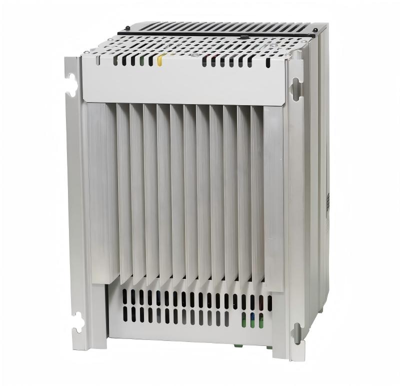
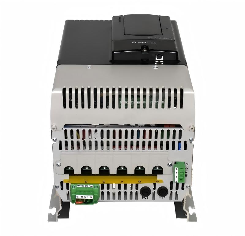
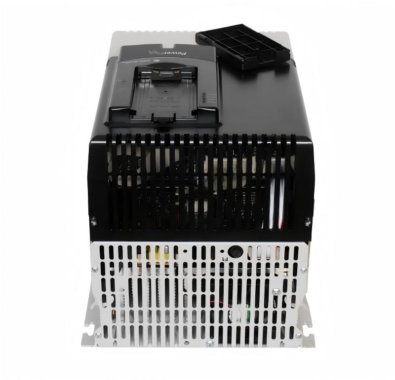
- Allen Bradley
- 20J1F3F2K3LNANNNNN
- PowerFlex AC Drive
- USA
- 2477 × 600 × 800 mm
- 3000kg
- Xiamen, China
- New & In Stock
- T/T, PayPal, Western Union
- 1 Year
- 1-3 Working Days
- DHL, UPS, TNT, FedEx and EMS.
- 24-Hour Service
- COO
- 4
Our advantage

Global Logistics
We have a 10-year logistics and express cooperation agreement, so our products can be shipped to any place in the world.

Brand new and original
Our products are imported in bulk from the place of origin. Because of the cooperative relationship, our products are all original and 100% new.

24-hour service
We provide 7*24 hours service to our customers. We will be there whenever you need us.

Price advantage
All our products are priced very favorably because we have our own warehouse and supply.
| Company Information | |||
| [email protected] | |||
| Mobile | +8615980777398 | ||
| +8615980777398 | |||
| 15980777398 |
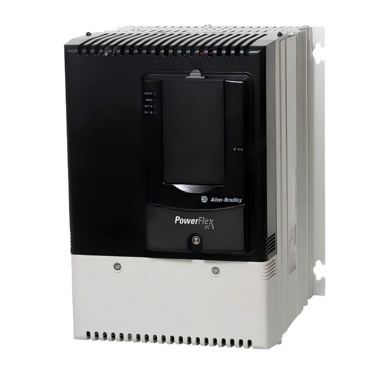
20J1F3F2K3LNANNNNN — Detailed Product Specifications, Introduction, Applications, Advantages and Related Models
1. Product Overview
The 20J1F3F2K3LNANNNNN is a high-power AC bus-supply configuration designed for demanding industrial drive systems. It belongs to the PowerFlex 750-class bus-supply platform and is intended for large machines and production systems where a common DC-bus architecture, high electrical power capacity and regenerative operation are required.
This model is an air-cooled 750 Bus Supply configured for AFE regenerative operation. It is designed for a 690 VAC, three-phase electrical system and is rated in the multi-megawatt range.
The specified configuration has a current rating of approximately 2,318 A, a normal-duty power rating of approximately 2,300 kW, and a heavy-duty power rating of approximately 2,000 kW. It uses a Frame 12 construction and a floor-mounted Type 1 / IP21 enclosure arrangement.
Unlike a small standalone variable-frequency drive, this type of equipment is normally used as part of a larger drive system. Its primary function is to establish and manage the DC-bus power required by connected inverter sections.
The architecture is particularly suitable for large industrial machinery containing multiple motors, coordinated drive sections or significant regenerative energy.
2. Brand and Product Series
| Item | Specification |
|---|---|
| Brand | Allen-Bradley |
| Product Family | PowerFlex 755T |
| Product Series | PowerFlex 755TM |
| Bus Supply Series | 20J1 |
| Product Type | 750 Bus Supply |
| Configuration Type | AFE Regenerative Bus Supply |
| Electrical Category | High-Power AC Drive System |
| Voltage Class | 690 VAC |
| Installation Type | Floor Mounted |
| Cooling | Air Cooled |
| Frame | Frame 12 |
| Enclosure | Type 1 / IP21 |
| Application Level | Multi-Megawatt Industrial Drive System |
The 20J1 designation identifies the bus-supply configuration family, while the complete catalog number specifies the particular electrical and mechanical configuration.
3. Basic Technical Parameters
| Parameter | Specification |
|---|---|
| Model | 20J1F3F2K3LNANNNNN |
| Brand | Allen-Bradley |
| Product Family | PowerFlex 755T |
| Product Series | PowerFlex 755TM |
| Product Type | 750 Bus Supply |
| Bus Supply Type | Air-Cooled AFE Regenerative |
| Input Voltage | 690 VAC |
| Input Phase | 3 Phase |
| Rated Current | Approx. 2,318 A |
| Normal-Duty Rating | Approx. 2,300 kW |
| Heavy-Duty Rating | Approx. 2,000 kW |
| Power Class | Approx. 2.3 MW |
| Active Front End | Yes |
| Regenerative Operation | Yes |
| Common DC Bus | Yes |
| Cooling Method | Air Cooled |
| Enclosure | Type 1 / IP21 |
| Installation | Floor Mounted |
| Frame Size | Frame 12 |
| EMC Option | No EMC |
| Jumper Configuration | Jumper Removed |
| HIM | No HIM in the specified configuration |
| Main Function | High-Power DC-Bus Power Supply |
| Typical System | Multi-Drive Common DC-Bus System |
| Approx. Width | Large multi-bay cabinet; approximately 2.6–3.5 m class depending on configuration |
| Approx. Depth | Approximately 0.7–0.9 m class depending on configuration |
| Approx. Height | Approximately 2.1–2.4 m class depending on configuration |
| Approx. Weight | Approximately 3,000 kg class for preliminary planning |
| Weight Unit | kg |
| Installation Environment | Industrial electrical room / dedicated drive area |
The electrical ratings are the most important characteristics of this model. The exact cabinet dimensions and shipping weight should be confirmed from the mechanical configuration before final installation planning.
4. Product Identification
The complete catalog number is:
20J1F3F2K3LNANNNNN
This is a highly configured industrial product number rather than a simple generic drive model.
Different sections of the catalog number represent different aspects of the equipment configuration, including the bus-supply family, voltage class, power configuration and other factory-selected options.
For replacement applications, the complete catalog number should always be matched.
A unit with a similar power rating but a different configuration code may have different electrical, mechanical, enclosure or installation characteristics.
5. Product Introduction
The 20J1F3F2K3LNANNNNN is designed for high-power industrial drive systems where conventional individual AC drives are not sufficient for the overall machine architecture.
The product works as a centralized power-conversion section.
A simplified system arrangement can be represented as:
Three-Phase AC Supply → AFE Bus Supply → Common DC Bus → Drive Inverter Sections → Motors
This architecture is especially useful when a machine has multiple high-power motors or several coordinated drive axes.
Instead of supplying each drive section through a completely independent power-conversion path, the system can use a centralized DC-bus structure.
This arrangement can also provide an efficient way of handling regenerative energy.
When a motor is accelerating, it consumes electrical energy.
When the motor decelerates or an overhauling load drives the motor, the motor can generate electrical energy.
With an appropriate regenerative system, that energy can be transferred back through the power-conversion system rather than being handled solely as heat through traditional braking equipment.
6. What Is an AFE Bus Supply?
AFE stands for Active Front End.
An Active Front End uses controlled power electronics at the input side of the drive system.
This differs from a basic uncontrolled rectifier arrangement.
The controlled front end allows the drive system to manage the relationship between the AC electrical supply and the DC bus more actively.
For large industrial systems, this architecture can be particularly valuable where the following characteristics are required:
- High installed motor power
- Regenerative operation
- Common DC-bus architecture
- Coordinated multi-drive operation
- Reduced dependence on conventional braking resistors
- Centralized power conversion
- High-power machine control
- Efficient energy management
The 20J1F3F2K3LNANNNNN therefore belongs to a category of equipment intended for large-scale industrial electrical systems.
7. Main Product Advantages
7.1 Multi-Megawatt Power Capacity
The approximately 2.3 MW normal-duty rating makes this configuration suitable for very large industrial applications.
It is intended for equipment where power requirements are measured in megawatts rather than the tens or hundreds of kilowatts normally associated with smaller industrial drives.
This allows the system to be used in large production machinery and heavy-duty material-handling equipment.
7.2 Regenerative Energy Capability
One of the major advantages of the AFE architecture is regenerative operation.
During braking or overhauling-load operation, a motor can return energy toward the DC bus.
Instead of simply converting all regenerative energy into heat, an appropriately designed regenerative system can return energy toward the AC supply.
This characteristic is valuable in applications with frequent acceleration and deceleration.
Typical examples include:
- Cranes
- Hoists
- Large conveyors
- Mining machinery
- Test systems
- High-inertia machines
- Metal-processing machinery
- Large lifting systems
7.3 Common DC-Bus Architecture
The common DC-bus concept is another important feature.
A large machine may contain several motors that operate at different times and under different load conditions.
One drive section may be accelerating while another drive section is decelerating.
With a common DC-bus architecture, the electrical power system can be designed around a shared DC energy source.
This can simplify the overall power architecture and provide additional flexibility for multi-drive systems.
7.4 High-Voltage Industrial Operation
The 690 VAC rating makes this configuration appropriate for large industrial electrical systems.
Higher-voltage drive systems can reduce the current required for a given power level compared with lower-voltage systems.
At multi-megawatt power levels, current management becomes a major design consideration because it directly affects:
- Cable size
- Busbar size
- Switchgear requirements
- Heat generation
- Connection design
- Electrical losses
- Installation space
7.5 Air-Cooled Construction
The product uses an air-cooled architecture.
Air cooling avoids the additional complexity associated with liquid-cooling systems and can simplify maintenance when the electrical room provides adequate ventilation.
However, at approximately 2.3 MW, the heat generated by the complete installation is substantial.
The installation area therefore needs appropriate airflow and heat-removal capability.
7.6 Industrial Floor-Mounted Design
The Frame 12 configuration is designed as a large floor-mounted industrial system.
This provides a robust arrangement for high-power electrical components and allows the equipment to be integrated into a dedicated electrical room or drive area.
Because of the physical size and mass, transportation, lifting and floor-loading requirements should be evaluated during the project planning stage.
8. Product Applications
8.1 Mining Equipment
Mining machinery frequently requires very high motor power.
Potential applications include:
- Large conveyors
- Crushers
- Hoists
- Material-handling systems
- Processing equipment
- High-power pumping systems
- Heavy-duty material transport
The high power rating and regenerative architecture make this type of bus supply suitable for demanding mining installations.
8.2 Large Conveyor Systems
Long conveyors can require multiple motors distributed across different sections.
A common DC-bus architecture can be advantageous for multi-motor conveyor systems.
Regenerative operation can also become important when a conveyor carries a large descending load or when a large rotating mass must be decelerated.
8.3 Cranes and Hoists
Cranes and hoists are among the applications where regenerative operation can be particularly valuable.
When a heavy load is lowered, mechanical energy is transferred into the motor.
The motor can operate as a generator, returning energy into the electrical system.
The AFE architecture can provide a controlled path for this regenerative energy.
8.4 Metal Processing Machinery
Large metal-processing machines can require multiple high-power motors operating together.
Potential applications include:
- Rolling equipment
- Heavy processing lines
- Winding and unwinding systems
- Material handling
- Large tension-control systems
- Continuous production machinery
The common DC-bus structure can support coordinated operation between several drive sections.
8.5 Large Industrial Test Systems
High-power test benches can also benefit from regenerative drive technology.
A test motor may accelerate a large mechanical load and then decelerate it repeatedly.
A regenerative architecture can recover energy during deceleration and return it to the electrical system.
This can reduce the need to dissipate large amounts of energy through braking resistors.
8.6 Heavy Material-Handling Equipment
Large industrial material-handling systems can involve high inertia and frequent acceleration/deceleration cycles.
The 20J1 architecture can be used where centralized high-power electrical conversion and regenerative operation are important requirements.
9. Typical System Architecture
A typical application can be represented as follows:
Incoming AC Power
↓
690 VAC Three-Phase Supply
↓
20J1 AFE Bus Supply
↓
Common DC Bus
↓
Multiple Inverter Sections
↓
Individual Motors
↓
Mechanical Machine
This structure is fundamentally different from a small standalone drive.
The bus supply provides the centralized DC power infrastructure, while individual inverter sections perform the motor-control function.
10. Advantages Compared with a Conventional Non-Regenerative Architecture
| Feature | Conventional Drive Architecture | 20J1 AFE Bus-Supply Architecture |
|---|---|---|
| Multi-drive operation | Possible but more decentralized | Designed around common DC-bus architecture |
| Regenerative operation | May require braking equipment | Integrated regenerative architecture |
| DC-bus sharing | Limited / application dependent | Central design feature |
| Power level | Small to high | Very high / multi-megawatt |
| Energy recovery | Depends on system design | Designed for regenerative operation |
| Installation | Individual drive cabinets | Large centralized power system |
| Typical application | Individual motors | Large multi-drive machinery |
| Cabinet size | Small to medium | Large floor-mounted |
| Cooling | Air or other methods | Air cooled in this configuration |
| Electrical infrastructure | Moderate to substantial | Very substantial |
11. Mechanical Parameters
The 20J1F3F2K3LNANNNNN is a large industrial cabinet system.
| Mechanical Parameter | Approximate Specification |
|---|---|
| Model | 20J1F3F2K3LNANNNNN |
| Installation | Floor mounted |
| Frame | Frame 12 |
| Cabinet Type | Large industrial cabinet / multi-bay configuration |
| Width | Approx. 2,600–3,500 mm class |
| Depth | Approx. 700–900 mm class |
| Height | Approx. 2,100–2,400 mm class |
| Approx. Weight | Approx. 3,000 kg |
| Weight Unit | kg |
| Cooling | Air cooled |
| Enclosure | Type 1 / IP21 |
| Installation Area | Dedicated industrial electrical area |
| Floor Loading | Must be checked according to actual equipment configuration |
| Transportation | Heavy equipment handling required |
| Lifting | Dedicated lifting arrangement recommended |
The dimensional values above are intended for preliminary planning.
For a final installation, the actual mechanical drawing for the complete cabinet arrangement should be used.
This is particularly important because large bus-supply systems can contain multiple cabinet sections and configuration-dependent mechanical assemblies.
12. Electrical Installation Considerations
A system at approximately 2.3 MW should not be treated like a conventional small VFD installation.
The electrical design should consider:
- Incoming supply voltage
- Transformer capacity
- Short-circuit capacity
- Input protection
- Disconnecting equipment
- Busbar sizing
- Cable sizing
- Grounding
- DC-bus protection
- Drive-section coordination
- Regenerative energy flow
- Harmonic performance
- Ventilation
- Electrical clearances
- Maintenance access
The high current rating of approximately 2,318 A means that electrical connections and busbar arrangements require careful engineering.
13. Environmental and Maintenance Considerations
The air-cooled design requires a clean and adequately ventilated installation environment.
The following areas should be inspected as part of routine maintenance:
- Cooling fans
- Air filters where applicable
- Airflow passages
- Power connections
- Busbar connections
- Control electronics
- Power semiconductor assemblies
- Grounding connections
- Cabinet ventilation
- Signs of overheating
- Mechanical connections
Dust and contamination can restrict airflow and increase operating temperature.
For a high-power system, temperature management is particularly important because thermal stress can affect the service life of power components.
14. Recommended Application Areas
| Application | Suitability |
|---|---|
| Large mining conveyor | Very suitable |
| Heavy-duty crane | Suitable |
| Large hoist | Suitable |
| Multi-motor conveyor | Very suitable |
| Metal-processing line | Suitable |
| High-power test bench | Suitable |
| Large material-handling machine | Very suitable |
| Multi-megawatt industrial machine | Very suitable |
| Small pump | Excessive capacity |
| Small fan | Excessive capacity |
| Small conveyor | Excessive capacity |
| Compact machine | Not normally appropriate |
The equipment should be selected according to the complete machine architecture rather than motor power alone.
15. Five Related Models from the Same Series
The following models are useful for comparison because they belong to the same general 20J1 bus-supply family.
They cover different power levels and frame sizes.
| Model | Product Type | Voltage | Approx. Power | Frame | Cooling | Approx. Dimensions | Approx. Weight |
|---|---|---|---|---|---|---|---|
| 20J1F3F1K1LNANNNNN | AFE 750 Bus Supply | 690 VAC | Approx. 1,180 kW | Frame 10 | Air cooled | Large cabinet, configuration dependent | Approx. 2,100 kg class |
| 20J1F3F1K4LNANNNNN | AFE 750 Bus Supply | 690 VAC | Approx. 1,456 kW | Frame 10 | Air cooled | Large cabinet, configuration dependent | Approx. 2,100–2,500 kg class |
| 20J1F3F1K8LNANNNNN | AFE 750 Bus Supply | 690 VAC | Approx. 1,914 kW | Frame 11 | Air cooled | Large multi-section cabinet | Approx. 2,500–2,700 kg class |
| 20J1F3F2K3LNANNNNN | AFE 750 Bus Supply | 690 VAC | Approx. 2,300 kW ND / 2,000 kW HD | Frame 12 | Air cooled | Approx. 2,600–3,500 × 700–900 × 2,100–2,400 mm class | Approx. 3,000 kg |
| 20J1F3F2K7LNANNNNN | AFE 750 Bus Supply | 690 VAC | Approx. 2,851 kW | Frame 13 | Air cooled | Very large multi-bay cabinet | Approx. 4,000–5,000 kg class |
These models should be regarded as related configurations rather than automatic replacement products.
A higher or lower power rating can change the frame, dimensions, current rating, cabinet arrangement, weight and installation requirements.
16. Same-Series Model Comparison
| Parameter | 20J1F3F1K1LNANNNNN | 20J1F3F1K4LNANNNNN | 20J1F3F1K8LNANNNNN | 20J1F3F2K3LNANNNNN | 20J1F3F2K7LNANNNNN |
|---|---|---|---|---|---|
| Voltage | 690 VAC | 690 VAC | 690 VAC | 690 VAC | 690 VAC |
| Power Class | ~1.18 MW | ~1.46 MW | ~1.91 MW | ~2.30 MW ND | ~2.85 MW |
| AFE | Yes | Yes | Yes | Yes | Yes |
| Regenerative | Yes | Yes | Yes | Yes | Yes |
| Common DC Bus | Yes | Yes | Yes | Yes | Yes |
| Cooling | Air | Air | Air | Air | Air |
| Installation | Floor mounted | Floor mounted | Floor mounted | Floor mounted | Floor mounted |
| Frame | 10 | 10 | 11 | 12 | 13 |
| Enclosure | IP21 / Type 1 | IP21 / Type 1 | IP21 / Type 1 | IP21 / Type 1 | IP21 / Type 1 |
| Approx. Weight | ~2,100 kg | ~2,100–2,500 kg | ~2,500–2,700 kg | ~3,000 kg | ~4,000–5,000 kg |
| Application | High power | High power | Very high power | Multi-megawatt | Multi-megawatt |
17. Five Related Popular Models from the Same Brand
The following models are useful for comparing the broader industrial-drive range.
They are not direct replacements for the 20J1F3F2K3LNANNNNN. Their power ratings, control architecture, installation method and application range can be substantially different.
| Model | Product Family | Product Type | Voltage Class | Approx. Power Class | Cooling | Approx. Dimensions | Approx. Weight |
|---|---|---|---|---|---|---|---|
| 25B-D017N114 | PowerFlex 525 | Compact AC Drive | 380–480 VAC class | Approx. 7.5 kW | Air cooled | Approx. 185 × 72 × 152 mm | Approx. 1.7 kg |
| 20F11NC022JA0NNNNN | PowerFlex 753 | AC Drive | 380–480 VAC class | Approx. 11–15 kW class | Air cooled | Configuration dependent | Approx. 20–40 kg class |
| 20F11NC034JA0NNNNN | PowerFlex 753 | AC Drive | 380–480 VAC class | Approx. 22–30 kW class | Air cooled | Configuration dependent | Approx. 30–60 kg class |
| 20G1ANB140JA0NNNNN | PowerFlex 755 | AC Drive | 400–480 VAC class | High-power class | Air cooled | Large cabinet / chassis configuration | Approx. 200–400 kg class |
| 20G1ANC350JA0NNNNN | PowerFlex 755 | AC Drive | 400–480 VAC class | High-power class | Air cooled | Large cabinet / chassis configuration | Approx. 300–500 kg class |
These products are useful when comparing different industrial motor-control requirements.
The PowerFlex 525-class product is aimed at compact machine applications, while the PowerFlex 753 and 755 families cover progressively larger and more sophisticated industrial drive requirements.
The 20J1 configuration occupies a substantially different position in the product range because it is a very-high-power bus-supply system.
18. Comparison of Broader Related Models
| Parameter | 25B-D017N114 | 20F11NC022JA0NNNNN | 20F11NC034JA0NNNNN | 20G1ANB140JA0NNNNN | 20G1ANC350JA0NNNNN |
|---|---|---|---|---|---|
| Product Type | Compact AC Drive | AC Drive | AC Drive | High-Power AC Drive | High-Power AC Drive |
| Typical Application | Machine control | Industrial motor | Industrial machinery | Heavy industrial equipment | Heavy industrial equipment |
| Voltage Class | 380–480 V | 380–480 V | 380–480 V | 400–480 V | 400–480 V |
| Power Level | ~7.5 kW | ~11–15 kW class | ~22–30 kW class | High power | High power |
| Cooling | Air | Air | Air | Air | Air |
| Installation | Compact | Cabinet/chassis | Cabinet/chassis | Industrial cabinet | Industrial cabinet |
| Regenerative Architecture | Not equivalent | Configuration dependent | Configuration dependent | Configuration dependent | Configuration dependent |
| Approx. Weight | ~1.7 kg | ~20–40 kg | ~30–60 kg | ~200–400 kg | ~300–500 kg |
| Approx. Size | 185 × 72 × 152 mm class | Configuration dependent | Configuration dependent | Large cabinet | Large cabinet |
19. Why the 20J1F3F2K3LNANNNNN Is Used in Large Systems
The primary reason for selecting a product of this type is the electrical architecture.
A multi-megawatt machine may have several motors operating together.
If every motor is supplied by an independent conventional drive, the machine can require a large amount of duplicated power-conversion equipment.
A centralized bus-supply architecture provides another approach.
The AFE bus supply establishes the DC-bus infrastructure, while individual inverter sections can be connected to the common DC system.
This is particularly useful when the machine has:
- Multiple motors
- High total installed power
- Frequent acceleration
- Frequent deceleration
- Regenerative loads
- High mechanical inertia
- Coordinated motion
- High continuous production requirements
20. Regenerative Energy Management
Regeneration is particularly important in high-inertia applications.
Consider a large hoisting system.
During lifting:
Electrical Energy → Motor → Mechanical Energy
During lowering:
Mechanical Energy → Motor → Electrical Energy
The second operating condition produces regenerative energy.
A suitable AFE system can manage this energy flow and return it toward the electrical supply.
This provides a significant functional difference compared with a system that relies only on resistive braking.
The practical benefit depends on the complete system design, operating cycle and electrical installation.
21. Advantages for Multi-Motor Machines
A common DC bus can provide several practical benefits.
Centralized power conversion
The main input power conversion can be concentrated in a high-capacity bus-supply section.
Shared DC-bus infrastructure
Multiple inverter sections can be arranged around a common electrical power source.
Regenerative energy management
Energy produced by regenerative drive sections can be managed through the common electrical system.
Coordinated operation
Multiple motors can be integrated into one overall machine-control architecture.
Scalable system design
Different inverter sections can be selected according to the requirements of individual motors.
22. Product Strengths at a Glance
| Advantage | Description |
|---|---|
| High power | Approximately 2.3 MW normal-duty capability |
| High current | Approximately 2,318 A |
| 690 V operation | Designed for large industrial electrical systems |
| AFE technology | Controlled front-end power conversion |
| Regeneration | Supports energy return during regenerative operation |
| Common DC bus | Suitable for multi-drive architecture |
| Air cooling | Practical industrial cooling arrangement |
| Floor mounted | Designed for large electrical installations |
| Large frame | Frame 12 high-power construction |
| Multi-motor capability | Suitable for systems with multiple inverter sections |
| Heavy industry | Suitable for demanding industrial machinery |
| Energy management | Particularly useful in applications with regenerative loads |
23. Product Selection Considerations
When selecting the 20J1F3F2K3LNANNNNN or a related model, the following information should be checked:
- Motor rated power.
- Motor rated voltage.
- Motor rated current.
- Number of motors.
- Required regenerative capability.
- Maximum acceleration current.
- Required overload capability.
- Duty cycle.
- Ambient temperature.
- Installation altitude.
- Cooling requirements.
- Incoming power system.
- Transformer capacity.
- Short-circuit current.
- Required enclosure.
- Cabinet arrangement.
- Cable-entry requirements.
- DC-bus configuration.
- Required inverter sections.
- Physical installation space.
For a multi-megawatt installation, motor power alone should not be used to select the final catalog configuration.
24. Storage and Installation Considerations
Because the equipment is large and heavy, storage and transportation require planning.
The installation team should consider:
- Indoor storage conditions
- Humidity control
- Dust protection
- Transportation route
- Door dimensions
- Floor loading
- Lifting equipment
- Cabinet positioning
- Service clearance
- Ventilation
- Cable routing
- Maintenance access
A unit weighing approximately 3,000 kg should be handled as heavy industrial equipment.
The actual shipping weight should be confirmed before transportation or lifting arrangements are finalized.
25. Maintenance Advantages of the Industrial Architecture
Although the equipment is large and complex, its industrial construction provides a structured approach to service and maintenance.
Routine maintenance can focus on:
- Cooling system condition
- Electrical connections
- Power modules
- DC-bus connections
- Control system
- Ventilation
- Cabinet cleanliness
- Grounding
- Thermal condition
A preventive-maintenance program is especially important for high-power equipment because unexpected downtime can have a significant effect on an entire production line.
26. Overall Technical Position
The 20J1F3F2K3LNANNNNN should be considered a high-capacity industrial power-conversion product rather than a conventional standalone motor inverter.
Its main characteristics are:
- 690 VAC three-phase input
- Approximately 2,318 A
- Approximately 2,300 kW normal duty
- Approximately 2,000 kW heavy duty
- Active Front End architecture
- Regenerative operation
- Common DC-bus capability
- Air cooling
- Frame 12
- Type 1 / IP21 enclosure
- Floor-mounted construction
- Multi-megawatt application capability
Its strongest application area is therefore large industrial machinery requiring centralized high-power electrical conversion and coordinated drive operation.
27. Final Product Specification Table
| Category | 20J1F3F2K3LNANNNNN |
|---|---|
| Brand | Allen-Bradley |
| Product Family | PowerFlex 755T |
| Product Series | PowerFlex 755TM |
| Bus-Supply Series | 20J1 |
| Product Type | 750 Bus Supply |
| Architecture | AFE Regenerative |
| Input Voltage | 690 VAC |
| Input | 3 Phase |
| Current | Approx. 2,318 A |
| Normal Duty | Approx. 2,300 kW |
| Heavy Duty | Approx. 2,000 kW |
| Power Class | Approx. 2.3 MW |
| Common DC Bus | Yes |
| Regenerative | Yes |
| Cooling | Air Cooled |
| Enclosure | Type 1 / IP21 |
| Installation | Floor Mounted |
| Frame | 12 |
| EMC | No EMC |
| Jumper | Removed |
| HIM | Not included in specified configuration |
| Approx. Width | 2,600–3,500 mm class |
| Approx. Depth | 700–900 mm class |
| Approx. Height | 2,100–2,400 mm class |
| Approx. Weight | Approx. 3,000 kg |
| Main Application | Multi-megawatt industrial drive system |
| Typical Industries | Mining, metals, material handling, cranes, heavy machinery, conveyors and test systems |
28. Conclusion
The 20J1F3F2K3LNANNNNN is a large-scale, high-power industrial bus-supply configuration designed for applications where a conventional standalone AC drive is not sufficient.
Its approximately 2.3 MW normal-duty capacity, 2,318 A current rating and 690 VAC three-phase input place it firmly within the multi-megawatt industrial-drive category.
The combination of Active Front End technology, regenerative operation and common DC-bus architecture makes it particularly suitable for large multi-motor machines and applications where substantial electrical energy can be recovered during braking or overhauling-load operation.
The product is especially relevant to mining machinery, large conveyors, cranes, hoists, metal-processing equipment, heavy material-handling systems and high-power industrial test equipment.
From a system-design perspective, one of its most important characteristics is that it is not simply a large version of a conventional VFD. It serves as a centralized high-power bus-supply section that can form the electrical foundation for multiple inverter sections.
The five closely related 20J1 configurations — 20J1F3F1K1LNANNNNN, 20J1F3F1K4LNANNNNN, 20J1F3F1K8LNANNNNN, 20J1F3F2K7LNANNNNN and 20J1F3F3K6LNANNNNN — provide useful alternatives across different power levels.
For smaller or more conventional motor-control requirements, products from the broader PowerFlex range, including 25B-D017N114, 20F11NC022JA0NNNNN, 20F11NC034JA0NNNNN, 20G1ANB140JA0NNNNN and 20G1ANC350JA0NNNNN, can be considered as related products, although they are not direct substitutes for the 20J1F3F2K3LNANNNNN.
For procurement, replacement or engineering design, the complete catalog number should always be matched against the required voltage, current, duty, enclosure, frame, cooling arrangement, regenerative requirements, cabinet configuration and mechanical installation requirements.