

ProductPRODUCT
Featured products
Contact Us
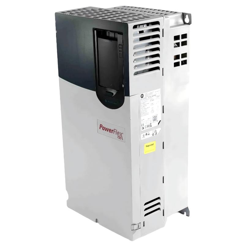
- Allen Bradley
- 20G1ANF212JA0NNNNN
- PowerFlex AC Drive
- USA
- 881.5 mm high × 430 mm wide × 349.6 mm deep
- 48kg
- Xiamen, China
- New & In Stock
- T/T, PayPal, Western Union
- 1 Year
- 1-3 Working Days
- DHL, UPS, TNT, FedEx and EMS.
- 24-Hour Service
- COO
- 4
Our advantage

Global Logistics
We have a 10-year logistics and express cooperation agreement, so our products can be shipped to any place in the world.

Brand new and original
Our products are imported in bulk from the place of origin. Because of the cooperative relationship, our products are all original and 100% new.

24-hour service
We provide 7*24 hours service to our customers. We will be there whenever you need us.

Price advantage
All our products are priced very favorably because we have our own warehouse and supply.
| Company Information | |||
| [email protected] | |||
| Mobile | +8615980777398 | ||
| +8615980777398 | |||
| 15980777398 |
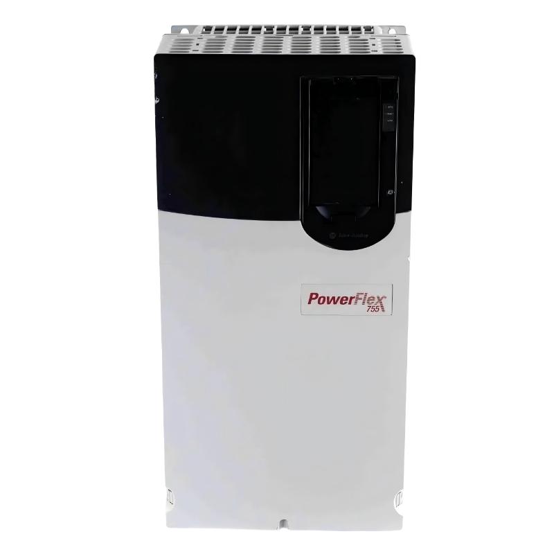
Allen-Bradley 20G1ANF212JA0NNNNN PowerFlex 755 AC Drive
1. Product Overview
The Allen-Bradley 20G1ANF212JA0NNNNN is a high-power industrial AC variable frequency drive belonging to the PowerFlex 755 series.
It is designed for demanding three-phase motor-control applications where high output power, high current capacity, controlled acceleration and deceleration, dynamic braking capability, and industrial network communication are required.
This model is rated for a 690 VAC three-phase power system and provides an output-current rating of approximately 212 A.
Its power rating is approximately 200 kW under Normal Duty (ND) and 160 kW under Heavy Duty (HD).
The drive uses a Frame 7 power structure with forced-air cooling and an open industrial construction intended for installation inside a suitable electrical cabinet or control enclosure.
A particularly important feature of the JA configuration is the inclusion of an internal dynamic-braking transistor.
This makes the 20G1ANF212JA0NNNNN different from the corresponding JN configuration, which does not include the internal dynamic-braking transistor.
The model also incorporates embedded EtherNet/IP communication, making it suitable for PLC-based automation systems, HMI systems, centralized drive control, process monitoring, and industrial network architectures.
2. Basic Product Information
| Parameter | Specification |
|---|---|
| Model | 20G1ANF212JA0NNNNN |
| Brand | Allen-Bradley |
| Series | PowerFlex 755 |
| Product Type | AC Variable Frequency Drive |
| Drive Family | PowerFlex 755 AC Drive |
| Voltage Class | 690 VAC |
| Input Phase | Three Phase |
| Output Current | 212 A |
| Normal Duty Rating | 200 kW |
| Heavy Duty Rating | 160 kW |
| Frame Size | Frame 7 |
| Cooling Method | Forced Air |
| Enclosure | IP20/IP00, Open Type |
| Input Configuration | AC Input with Precharge |
| DC Terminals | No |
| Dynamic Braking | Internal DB Transistor |
| Filtering | Filtered |
| CM Jumper | Installed |
| Communication | Embedded EtherNet/IP |
| HIM | Blank / No HIM |
| Installation | Industrial Cabinet / Panel |
| Height | Approx. 881.5 mm |
| Width | Approx. 430 mm |
| Depth | Approx. 349.6 mm |
| Approx. Weight | Approx. 48 kg |
| Duty Capability | Normal Duty / Heavy Duty |
| Application Type | High-Power Industrial Motor Control |
3. Brand and Series
Brand: Allen-Bradley
The 20G1ANF212JA0NNNNN is an Allen-Bradley industrial variable-frequency drive designed for professional automation and motor-control applications.
The product is intended for integration into industrial electrical systems, process-control systems, machine-control systems, and large motor installations.
Series: PowerFlex 755
The product belongs to the PowerFlex 755 series.
The PowerFlex 755 family is designed for high-performance industrial AC motor control and covers a broad range of motor ratings, current classes, voltage classes, frame sizes, control configurations, communication options, and braking requirements.
The 690 VAC models are particularly suitable for high-power applications where large motors are operated from a high-voltage industrial electrical system.
4. Detailed Technical Specifications
| Technical Parameter | 20G1ANF212JA0NNNNN |
|---|---|
| Model | 20G1ANF212JA0NNNNN |
| Brand | Allen-Bradley |
| Series | PowerFlex 755 |
| Voltage | 690 VAC |
| Phase | Three Phase |
| Output Current | 212 A |
| Normal Duty Power | 200 kW |
| Heavy Duty Power | 160 kW |
| Frame | Frame 7 |
| Cooling | Forced Air |
| Enclosure Rating | IP20/IP00 |
| Enclosure Type | NEMA/UL Open Type |
| Input Type | AC Input with Precharge |
| DC Input Terminals | No |
| Dynamic Braking | DB Transistor |
| Filtering | Filtered |
| CM Capacitor Jumper | Installed |
| Communication | Embedded EtherNet/IP |
| HIM | Blank / No HIM |
| Control Application | Industrial AC Motor Control |
| Height | Approx. 881.5 mm |
| Width | Approx. 430 mm |
| Depth | Approx. 349.6 mm |
| Weight | Approx. 48 kg |
| Cooling Airflow | Forced Air |
| Mounting | Cabinet / Panel Installation |
5. Electrical Rating
The 212 A output-current rating is the main electrical characteristic of this drive.
At the 690 VAC voltage class, the drive is designed for large industrial motors and high-capacity mechanical equipment.
The drive provides approximately:
- 200 kW Normal Duty
- 160 kW Heavy Duty
The two duty ratings allow the drive to be applied to different types of motor loads.
Normal Duty is generally associated with applications where the motor operates with comparatively moderate overload requirements.
Heavy Duty is intended for applications with greater torque demand, more demanding acceleration, higher cyclic loading, or more severe overload conditions.
The actual motor full-load current should always be checked against the applicable drive current rating during engineering selection.
6. Normal Duty and Heavy Duty Ratings
| Rating | Specification |
|---|---|
| Model | 20G1ANF212JA0NNNNN |
| Voltage | 690 VAC |
| Output Current | 212 A |
| Normal Duty | 200 kW |
| Heavy Duty | 160 kW |
| Frame | Frame 7 |
| Cooling | Forced Air |
| Phase | Three Phase |
The 200 kW Normal Duty rating makes this drive suitable for large pumps, fans, blowers, conveyors, process machinery, material-handling equipment, and other high-power rotating equipment.
The 160 kW Heavy Duty rating provides a lower motor-power classification because heavy-duty operation places greater thermal and electrical demands on the drive.
When the application involves frequent starting and stopping, high acceleration torque, rapid load changes, or high-inertia machinery, the Heavy Duty rating should be used as an important selection reference.
7. 690 VAC Three-Phase Operation
The 20G1ANF212JA0NNNNN is designed for a 690 VAC three-phase industrial power system.
The 690 V class is commonly used in larger industrial installations where substantial motor power needs to be transmitted and controlled.
For the same approximate power level, a higher motor voltage allows the operating current to remain lower than it would be on a lower-voltage system.
This can be beneficial when designing large motor installations, switchgear systems, motor feeders, and industrial control cabinets.
The actual incoming power system should always be checked against the drive’s specified voltage range and installation requirements.
8. Frame 7 Construction
The 20G1ANF212JA0NNNNN uses a Frame 7 power section.
Frame 7 is intended for high-power PowerFlex 755 applications and provides a larger mechanical and thermal platform than the smaller frame configurations.
The larger frame accommodates the power electronics and cooling requirements associated with the 212 A current class.
For cabinet design, sufficient room should be allowed for:
- Drive installation.
- Power cable routing.
- Control wiring.
- Cooling airflow.
- Maintenance access.
- Fan service.
- Electrical clearances.
- Grounding connections.
- Removal and replacement of major components.
9. Dimensions and Weight
The physical dimensions of this model are suitable for high-power industrial cabinet installations.
The approximate mechanical dimensions are:
Height: 881.5 mm
Width: 430 mm
Depth: 349.6 mm
Weight: approximately 48 kg
| Mechanical Parameter | Specification |
|---|---|
| Model | 20G1ANF212JA0NNNNN |
| Frame | Frame 7 |
| Height | Approx. 881.5 mm |
| Width | Approx. 430 mm |
| Depth | Approx. 349.6 mm |
| Overall Size | Approx. 881.5 × 430 × 349.6 mm |
| Net Weight | Approx. 48 kg |
| Enclosure | IP20/IP00 Open Type |
| Cooling | Forced Air |
| Installation | Cabinet / Panel |
| Service Clearance | Required |
| Airflow Clearance | Required |
The stated dimensions and weight should be treated as equipment-reference values. Final cabinet design should allow additional space for wiring, ventilation, cable bending radius, service access, and any installation accessories.
10. AC Input with Precharge
The model uses an AC input with precharge and no DC terminals.
The precharge system controls the initial charging process of the drive’s internal DC bus capacitors when the drive is energized.
This is particularly important for high-power equipment because the internal DC bus contains substantial stored energy.
The configuration is intended primarily for conventional AC-fed motor-drive systems.
The absence of external DC terminals also distinguishes this configuration from certain PowerFlex 755 variants designed specifically for different DC-bus arrangements.
11. Dynamic Braking Capability
One of the most important characteristics of the JA configuration is the presence of an internal dynamic-braking transistor.
The 20G1ANF212JA0NNNNN includes a DB transistor.
Dynamic braking is useful when a motor needs to decelerate more rapidly than would normally occur through natural mechanical deceleration.
During deceleration, the motor can return energy toward the drive’s DC bus. A dynamic-braking system can manage this energy and dissipate it through an appropriate braking resistor arrangement.
This is particularly useful for applications involving:
- High-inertia loads.
- Rapid stopping.
- Frequent acceleration and deceleration.
- Large conveyors.
- Centrifuges.
- Material-handling equipment.
- Unwinders and winders.
- Large rotating machinery.
- Hoisting-related machinery where the overall drive architecture permits its use.
The internal DB transistor does not mean that every application automatically has a complete braking-resistor system.
The external braking resistor and associated system design must be selected according to the actual regenerative energy, stopping time, duty cycle, and application requirements.
12. JA Versus JN Configuration
The corresponding JN model provides a useful comparison.
| Feature | JA Configuration | JN Configuration |
|---|---|---|
| Model Example | 20G1ANF212JA0NNNNN | 20G1ANF212JN0NNNNN |
| Voltage | 690 VAC | 690 VAC |
| Output Current | 212 A | 212 A |
| Normal Duty | 200 kW | 200 kW |
| Heavy Duty | 160 kW | 160 kW |
| Frame | Frame 7 | Frame 7 |
| Cooling | Forced Air | Forced Air |
| Filtering | Filtered | Filtered |
| CM Jumper | Installed | Installed |
| Dynamic Braking | DB Transistor | None |
| HIM | Blank / No HIM | Blank / No HIM |
| EtherNet/IP | Embedded | Embedded |
The principal difference is the dynamic-braking configuration.
For an application where an internal braking transistor is required, the JA configuration is the relevant configuration to evaluate.
For applications where dynamic braking is not required, the corresponding JN configuration may be considered.
13. Embedded EtherNet/IP
The drive includes embedded EtherNet/IP communication.
This allows the drive to be integrated directly into a networked industrial control architecture.
Typical communication functions can include:
- Start and stop commands.
- Speed reference.
- Frequency reference.
- Motor current monitoring.
- Motor speed monitoring.
- Drive status.
- Fault status.
- Alarm information.
- Parameter access.
- Diagnostic information.
- PLC control.
- HMI monitoring.
- Supervisory control.
- Production data collection.
The integrated communication capability is particularly useful in plants where multiple variable-frequency drives need to be controlled from a central automation system.
14. No HIM Configuration
The model is supplied as Blank / No HIM.
HIM means Human Interface Module.
A no-HIM configuration is often appropriate when the drive is installed in a centralized control cabinet and operators interact with the equipment through a PLC, HMI, SCADA system, or industrial Ethernet network.
This configuration also reduces the need for a local operator keypad on the front of every drive.
If local operator adjustment is required, a compatible human-interface solution can be added according to the system design.
15. Filtered Configuration
The 20G1ANF212JA0NNNNN is specified with a filtered configuration and CM jumper installed.
This arrangement is useful in industrial environments where electromagnetic compatibility and common-mode electrical behavior are important design considerations.
Filtering can be beneficial in installations containing:
- Multiple variable-frequency drives.
- Long motor cables.
- Sensitive control equipment.
- Instrumentation systems.
- Industrial Ethernet equipment.
- PLC systems.
- Analog measurement equipment.
- Other electronic equipment installed in the same electrical environment.
Correct grounding and motor-cable practices remain essential.
The drive filter should not be considered a substitute for proper cabinet grounding, cable shielding, cable routing, and system-level EMC engineering.
16. Product Introduction
The 20G1ANF212JA0NNNNN is a high-capacity industrial AC drive intended for large motor applications.
With a 212 A current rating and 200 kW Normal Duty capability, it is positioned toward the high-power end of the PowerFlex 755 family.
The combination of 690 VAC operation and Frame 7 construction makes the drive suitable for large industrial equipment where motor power and system voltage are considerably higher than those found in small machine applications.
The integrated EtherNet/IP interface allows the drive to become part of a larger automation system instead of functioning as an isolated motor controller.
The internal dynamic-braking transistor further expands the range of applications by providing a drive configuration suitable for systems where controlled braking and energy management during deceleration are required.
17. Main Product Advantages
17.1 High 200 kW Normal Duty Rating
The 200 kW Normal Duty rating makes this model suitable for large industrial motors.
It provides significantly greater motor-control capacity than the smaller 132 kW and 160 kW-class models in the same voltage family.
17.2 212 A Output Current
The 212 A output-current class allows the drive to support large motors and high-power mechanical systems.
The current rating is especially important for applications with substantial continuous motor loading.
17.3 690 VAC Platform
The 690 VAC platform is appropriate for large industrial electrical systems.
It is particularly useful where high motor power must be delivered without moving to extremely high operating currents.
17.4 Internal Dynamic-Braking Transistor
The internal DB transistor is one of the most important advantages of the JA configuration.
It provides a drive architecture suitable for applications where regenerative energy during deceleration must be managed through a braking resistor system.
17.5 Embedded EtherNet/IP
Integrated EtherNet/IP provides a convenient method for connecting the drive to industrial automation systems.
This supports centralized control, monitoring, diagnostics, and production management.
17.6 Frame 7 High-Power Design
The Frame 7 structure is intended for high-power applications and provides the physical platform required for the 212 A class.
17.7 Forced-Air Cooling
Forced-air cooling provides the airflow needed to remove heat generated by the high-power switching components.
For reliable operation, cabinet airflow and environmental conditions must be managed correctly.
17.8 Industrial Open-Type Construction
The IP20/IP00 open-type design allows the drive to be integrated into a larger industrial electrical enclosure.
This provides flexibility for custom cabinet construction.
18. Typical Applications
Large Industrial Pumps
The drive is suitable for large process pumps, circulation pumps, cooling-water pumps, water-treatment pumps, and other high-power pumping systems.
Variable-speed operation allows pump speed to be adjusted according to process demand.
Large Fans
Industrial ventilation fans, cooling fans, exhaust systems, combustion-air fans, and process blowers can require high-power motor control.
The drive can regulate fan speed while allowing the automation system to monitor operating conditions.
Conveyors
Large conveyors used in mining, bulk material handling, manufacturing, and processing facilities can benefit from controlled acceleration and deceleration.
The internal dynamic-braking transistor is particularly relevant where rapid stopping or controlled deceleration is required.
Material Handling
High-power material-handling equipment can require accurate speed regulation and coordinated control.
Examples include:
- Belt conveyors.
- Feeders.
- Transfer systems.
- Bulk material transport equipment.
- Large processing conveyors.
Mining Equipment
Mining operations frequently use high-power motors for pumps, conveyors, ventilation systems, crushers, material-handling systems, and processing equipment.
The 690 VAC / 212 A configuration is appropriate for selected high-power installations where the environmental and cabinet requirements are satisfied.
Water and Wastewater Systems
Large pumping stations, treatment systems, aeration equipment, and process-water installations can use variable-frequency drives to regulate flow and motor speed.
Process Machinery
Mixers, agitators, large rotating equipment, and industrial process machinery can benefit from controlled speed and torque.
Large Blowers
Industrial air systems and process blowers can use the drive to control airflow according to production requirements.
19. Application Reference Table
| Application | Typical Requirement | Product Benefit |
|---|---|---|
| Large Pump | High motor power | Variable-speed control |
| Industrial Fan | Large motor | Adjustable airflow |
| Large Blower | Continuous operation | Speed regulation |
| Conveyor | High starting torque | Controlled acceleration |
| Material Handling | High motor power | Networked control |
| Mining Equipment | Large industrial motor | High-current capability |
| Water Treatment | Large pump/blower | Process-speed control |
| Cooling System | High-power pump/fan | Adjustable output |
| Process Machinery | Variable-speed operation | Centralized automation |
| High-Inertia Machinery | Controlled stopping | Internal DB transistor |
20. Installation Considerations
Because the 20G1ANF212JA0NNNNN is an IP20/IP00 open-type drive, it should normally be installed inside a suitable electrical cabinet or protected industrial enclosure.
The installation environment should provide appropriate protection from excessive dust, moisture, corrosive substances, and other contaminants.
Adequate airflow is particularly important because the drive uses forced-air cooling.
The cabinet should provide sufficient clearance around the drive so that cooling air can move through the equipment without excessive restriction.
Important installation factors include:
- Input power protection.
- Proper grounding.
- Motor cable selection.
- Motor cable routing.
- Control cable routing.
- EtherNet/IP cable installation.
- Cabinet ventilation.
- Cooling fan access.
- Service clearance.
- Environmental protection.
- EMC considerations.
- Braking resistor installation where required.
21. Dynamic Braking Application Considerations
The JA configuration is particularly useful when the motor must decelerate quickly.
When a high-inertia load slows down, mechanical energy is transferred back through the motor into the drive system.
Without an appropriate energy-management method, the DC-bus voltage can rise during aggressive deceleration.
A properly engineered dynamic-braking system can dissipate this energy through a braking resistor.
Typical applications that may require such capability include:
- Large conveyors.
- High-speed rotating equipment.
- Centrifugal machinery.
- Large fans with substantial inertia.
- Material-handling equipment.
- Machines with frequent stop/start cycles.
- Certain hoisting-related systems.
The braking resistor must be correctly sized for the application.
Important factors include:
- Motor power.
- Motor speed.
- Load inertia.
- Deceleration time.
- Number of braking cycles.
- Braking frequency.
- Ambient temperature.
- Resistor duty rating.
The internal DB transistor provides the switching capability, while the complete braking system must still be engineered according to the actual application.
22. Maintenance Considerations
Routine inspection is important for high-power variable-frequency drives.
The cooling system should be inspected periodically to ensure that airflow is not restricted.
Dust accumulation can reduce cooling performance and increase the operating temperature of the power electronics.
Recommended maintenance activities include:
- Inspecting cooling fans.
- Checking ventilation openings.
- Inspecting power connections.
- Checking control wiring.
- Inspecting grounding connections.
- Reviewing drive fault history.
- Monitoring abnormal temperature conditions.
- Inspecting the cabinet for contamination.
- Checking Ethernet communication.
- Inspecting braking components where installed.
- Checking motor cable connections.
Regular maintenance helps reduce unexpected downtime and can improve the service life of the overall drive system.
23. Five Same-Series Recommended Models
The following models are closely related PowerFlex 755 models in the same 690 VAC family.
| Model | Voltage | Output Current | Normal Duty | Heavy Duty | Frame | Cooling | Dynamic Braking |
|---|---|---|---|---|---|---|---|
| 20G1ANF142JA0NNNNN | 690 VAC | 142 A | 132 kW | 110 kW | Frame 6 | Forced Air | DB Transistor |
| 20G1ANF171JA0NNNNN | 690 VAC | 171 A | 160 kW | 132 kW | Frame 7 | Forced Air | DB Transistor |
| 20G1ANF212JA0NNNNN | 690 VAC | 212 A | 200 kW | 160 kW | Frame 7 | Forced Air | DB Transistor |
| 20G1ANF263JA0NNNNN | 690 VAC | 263 A | 250 kW | 200 kW | Frame 7 | Forced Air | DB Transistor |
| 20G1ANF119JA0NNNNN | 690 VAC | 119 A | 110 kW | 90 kW | Frame 6 | Forced Air | DB Transistor |
These models provide a useful progression for applications where the motor rating changes but the 690 VAC PowerFlex 755 platform remains the preferred architecture.
24. Recommended Model 1 – 20G1ANF142JA0NNNNN
The 20G1ANF142JA0NNNNN is a lower-current 690 VAC model within the same family.
It provides approximately 142 A output current, 132 kW Normal Duty capability, and 110 kW Heavy Duty capability.
It is suitable when the motor load is below the 212 A range.
| Parameter | Specification |
|---|---|
| Model | 20G1ANF142JA0NNNNN |
| Voltage | 690 VAC |
| Output Current | 142 A |
| Normal Duty | 132 kW |
| Heavy Duty | 110 kW |
| Frame | Frame 6 |
| Cooling | Forced Air |
| Dynamic Braking | DB Transistor |
| Filtering | Filtered |
| Communication | Embedded EtherNet/IP |
25. Recommended Model 2 – 20G1ANF171JA0NNNNN
The 20G1ANF171JA0NNNNN is another closely related model.
It uses the same 690 VAC platform and JA dynamic-braking configuration but provides a lower current rating of approximately 171 A.
Its approximate ratings are 160 kW Normal Duty and 132 kW Heavy Duty.
| Parameter | Specification |
|---|---|
| Model | 20G1ANF171JA0NNNNN |
| Voltage | 690 VAC |
| Output Current | 171 A |
| Normal Duty | 160 kW |
| Heavy Duty | 132 kW |
| Frame | Frame 7 |
| Cooling | Forced Air |
| Dynamic Braking | DB Transistor |
| Filtering | Filtered |
| Communication | Embedded EtherNet/IP |
26. Recommended Model 3 – 20G1ANF263JA0NNNNN
The 20G1ANF263JA0NNNNN is a higher-capacity model than the target drive.
It provides approximately 263 A output current and is rated at approximately 250 kW Normal Duty and 200 kW Heavy Duty.
It is intended for larger motor systems where the 212 A current class is not sufficient.
| Parameter | Specification |
|---|---|
| Model | 20G1ANF263JA0NNNNN |
| Voltage | 690 VAC |
| Output Current | 263 A |
| Normal Duty | 250 kW |
| Heavy Duty | 200 kW |
| Frame | Frame 7 |
| Cooling | Forced Air |
| Dynamic Braking | DB Transistor |
| Filtering | Filtered |
| Communication | Embedded EtherNet/IP |
27. Recommended Model 4 – 20G1ANF119JA0NNNNN
The 20G1ANF119JA0NNNNN is a smaller 690 VAC PowerFlex 755 configuration.
It provides approximately 119 A output current, 110 kW Normal Duty capability, and 90 kW Heavy Duty capability.
It is useful for applications where the motor rating is significantly below the 212 A class.
| Parameter | Specification |
|---|---|
| Model | 20G1ANF119JA0NNNNN |
| Voltage | 690 VAC |
| Output Current | 119 A |
| Normal Duty | 110 kW |
| Heavy Duty | 90 kW |
| Frame | Frame 6 |
| Cooling | Forced Air |
| Dynamic Braking | DB Transistor |
| Filtering | Filtered |
| Communication | Embedded EtherNet/IP |
28. Recommended Model 5 – 20G1ANF212JN0NNNNN
The 20G1ANF212JN0NNNNN has essentially the same main voltage, current, power, and frame classification as the target model.
The principal configuration difference is dynamic braking.
The JA version includes the internal DB transistor, while the JN version does not.
| Parameter | Specification |
|---|---|
| Model | 20G1ANF212JN0NNNNN |
| Voltage | 690 VAC |
| Output Current | 212 A |
| Normal Duty | 200 kW |
| Heavy Duty | 160 kW |
| Frame | Frame 7 |
| Cooling | Forced Air |
| Dynamic Braking | None |
| Filtering | Filtered |
| Communication | Embedded EtherNet/IP |
This model is particularly useful as a direct configuration comparison when dynamic braking is not required.
29. Five Related Popular Models Under the Same Brand
| Model | Series | Voltage | Output Current | Normal Duty | Heavy Duty | Frame |
|---|---|---|---|---|---|---|
| 20G1ANF171JA0NNNNN | PowerFlex 755 | 690 VAC | 171 A | 160 kW | 132 kW | Frame 7 |
| 20G1ANF212JN0NNNNN | PowerFlex 755 | 690 VAC | 212 A | 200 kW | 160 kW | Frame 7 |
| 20G1ANF263JA0NNNNN | PowerFlex 755 | 690 VAC | 263 A | 250 kW | 200 kW | Frame 7 |
| 20G1ANF142JA0NNNNN | PowerFlex 755 | 690 VAC | 142 A | 132 kW | 110 kW | Frame 6 |
| 20G1ANC170JA0NNNNN | PowerFlex 755 | 400 VAC | 170 A | 90 kW | 75 kW | Frame 6 |
30. Voltage-Class Comparison
The PowerFlex 755 family contains models for different industrial voltage systems.
| Model | Voltage Class | Current | ND Rating | HD Rating | Frame |
|---|---|---|---|---|---|
| 20G1ANC170JA0NNNNN | 400 VAC | 170 A | 90 kW | 75 kW | 6 |
| 20G1AND156JA0NNNNN | 480 VAC | 156 A | 125 HP | 100 HP | 6 |
| 20G1ANF142JA0NNNNN | 690 VAC | 142 A | 132 kW | 110 kW | 6 |
| 20G1ANF171JA0NNNNN | 690 VAC | 171 A | 160 kW | 132 kW | 7 |
| 20G1ANF212JA0NNNNN | 690 VAC | 212 A | 200 kW | 160 kW | 7 |
| 20G1ANF263JA0NNNNN | 690 VAC | 263 A | 250 kW | 200 kW | 7 |
The appropriate model should be selected according to the actual facility voltage and motor full-load current rather than selecting only by nominal motor power.
31. Product Comparison Within the 690 VAC Family
| Model | Current | ND | HD | Frame | Dynamic Braking |
|---|---|---|---|---|---|
| 20G1ANF119JA0NNNNN | 119 A | 110 kW | 90 kW | 6 | DB Transistor |
| 20G1ANF142JA0NNNNN | 142 A | 132 kW | 110 kW | 6 | DB Transistor |
| 20G1ANF171JA0NNNNN | 171 A | 160 kW | 132 kW | 7 | DB Transistor |
| 20G1ANF212JA0NNNNN | 212 A | 200 kW | 160 kW | 7 | DB Transistor |
| 20G1ANF263JA0NNNNN | 263 A | 250 kW | 200 kW | 7 | DB Transistor |
This progression makes the 20G1ANF212JA0NNNNN a high-capacity model positioned between the 171 A and 263 A versions.
32. Cabinet Design Considerations
The physical dimensions of approximately 881.5 × 430 × 349.6 mm should be considered when designing the control cabinet.
The cabinet should provide more space than the basic drive dimensions alone.
Additional space may be necessary for:
- Incoming power cables.
- Motor output cables.
- Control wiring.
- Ethernet communication cables.
- Grounding conductors.
- Braking-resistor connections.
- Cooling airflow.
- Cable bends.
- Maintenance access.
- Fan replacement.
- Electrical inspection.
- Safe working clearance.
The drive should not be installed in a cabinet where surrounding components significantly restrict airflow.
33. Environmental Considerations
The drive is intended for industrial environments, but the installation environment still needs to be controlled.
Important environmental factors include:
- Ambient temperature.
- Dust.
- Humidity.
- Condensation.
- Corrosive gases.
- Airborne particles.
- Cooling-air quality.
- Vibration.
- Cabinet ventilation.
- Altitude.
Where the drive is installed in a harsh environment, cabinet design should provide suitable environmental protection.
The open-type construction should not be treated as equivalent to a sealed outdoor enclosure.
34. Why the 20G1ANF212JA0NNNNN Is Used for Large Industrial Equipment
Large motors often require more than simple start/stop control.
A modern industrial motor-control system may need:
- Variable-speed operation.
- Controlled acceleration.
- Controlled deceleration.
- Torque regulation.
- Process feedback.
- Network communication.
- Fault monitoring.
- Alarm handling.
- Dynamic braking.
- Energy management.
- Centralized PLC control.
The 20G1ANF212JA0NNNNN combines these requirements into a high-power drive platform.
The 212 A current rating provides substantial motor capacity, while the 200 kW Normal Duty rating allows the drive to be used on large industrial machines.
The internal dynamic-braking transistor is especially useful when controlled deceleration is part of the application requirements.
35. Key Product Advantages Summary
| Advantage | Detailed Description |
|---|---|
| 690 VAC Operation | Designed for high-voltage industrial motor systems |
| 212 A Output | Supports large industrial motors |
| 200 kW ND | High Normal Duty motor capacity |
| 160 kW HD | Defined Heavy Duty operating capacity |
| Frame 7 | High-power mechanical and electrical platform |
| DB Transistor | Supports dynamic-braking system design |
| Embedded EtherNet/IP | Direct industrial network integration |
| Forced-Air Cooling | Suitable for high-power applications |
| Filtered Configuration | Supports EMC-conscious installations |
| CM Jumper Installed | Factory-configured common-mode arrangement |
| AC Input with Precharge | Conventional high-power AC drive architecture |
| No DC Terminals | Dedicated AC input configuration |
| No HIM | Suitable for centralized PLC/HMI control |
| IP20/IP00 Open Type | Flexible cabinet integration |
| 48 kg Approx. Weight | Practical reference for equipment handling |
36. Selection Checklist
Before using the 20G1ANF212JA0NNNNN in an actual project, the following parameters should be verified.
| Selection Item | Required Check |
|---|---|
| Model | 20G1ANF212JA0NNNNN |
| Supply Voltage | Confirm 690 VAC three-phase |
| Motor Current | Confirm motor FLA against drive rating |
| Motor Power | Check 200 kW ND / 160 kW HD |
| Duty | Determine ND or HD requirement |
| Braking | Determine whether dynamic braking is required |
| Braking Resistor | Size according to actual application |
| Cooling | Confirm sufficient forced-air ventilation |
| Cabinet | Verify enclosure space |
| Dimensions | 881.5 × 430 × 349.6 mm approx. |
| Weight | 48 kg approx. |
| Communication | Confirm EtherNet/IP requirements |
| HIM | No standard HIM |
| Motor Cable | Verify conductor size and installation |
| Grounding | Verify system grounding |
| EMC | Check filter and CM configuration |
| Environment | Check temperature, dust, humidity, and altitude |
| Maintenance | Provide adequate service access |
37. Overall Product Summary
The Allen-Bradley 20G1ANF212JA0NNNNN is a high-power PowerFlex 755 AC variable frequency drive designed for large industrial motor-control applications.
Its primary electrical characteristics are 690 VAC three-phase input, 212 A output current, 200 kW Normal Duty capacity, and 160 kW Heavy Duty capacity.
The drive uses a Frame 7 construction with forced-air cooling and an open-type IP20/IP00 design intended for integration into an industrial electrical cabinet.
Its approximate physical dimensions are 881.5 mm high × 430 mm wide × 349.6 mm deep, with an approximate equipment weight of 48 kg.
One of the defining characteristics of the JA configuration is the internal dynamic-braking transistor.
This makes the 20G1ANF212JA0NNNNN particularly relevant to high-power machinery where controlled deceleration and management of regenerative energy are important design requirements.
The drive also includes embedded EtherNet/IP communication, allowing it to be integrated into PLC-controlled production systems, HMI platforms, supervisory systems, and larger industrial automation networks.
Its filtered configuration and installed CM jumper provide a suitable foundation for industrial EMC considerations, while proper grounding, motor-cable routing, shielding, and cabinet design remain important parts of the complete installation.
Typical applications include large pumps, fans, blowers, conveyors, mining equipment, material-handling machinery, water-treatment systems, process machinery, and other large rotating industrial equipment.
Within the same 690 VAC family, the 20G1ANF142JA0NNNNN, 20G1ANF171JA0NNNNN, 20G1ANF263JA0NNNNN, and 20G1ANF212JN0NNNNN provide useful alternatives depending on current capacity and dynamic-braking requirements.
For applications requiring approximately 212 A of output current, up to 200 kW Normal Duty, and an internal dynamic-braking transistor, the 20G1ANF212JA0NNNNN represents a high-capacity Frame 7 configuration intended for demanding industrial motor-control systems.