

ProductPRODUCT
Featured products
Contact Us
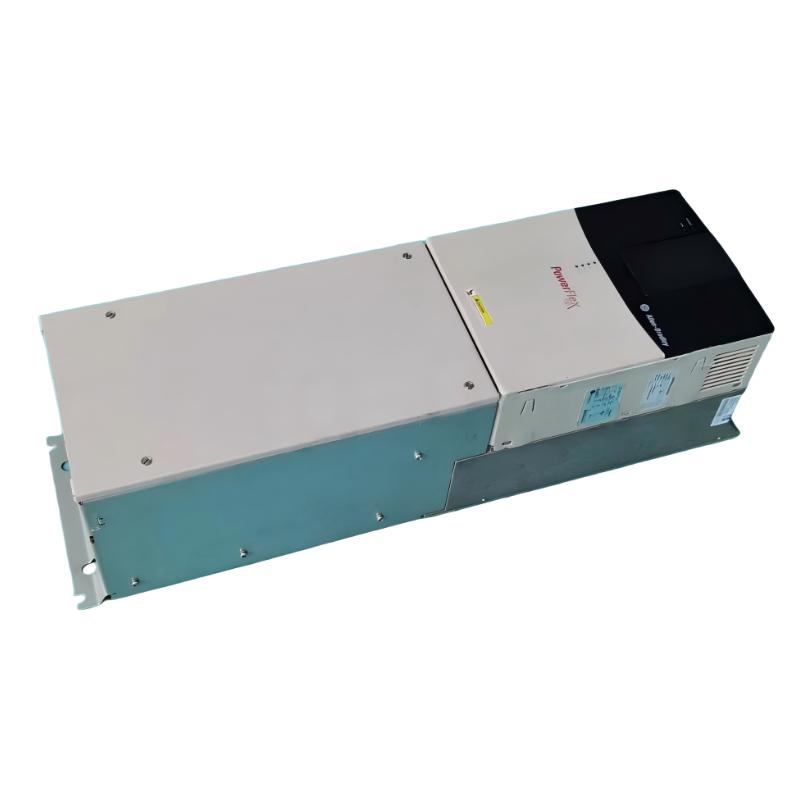
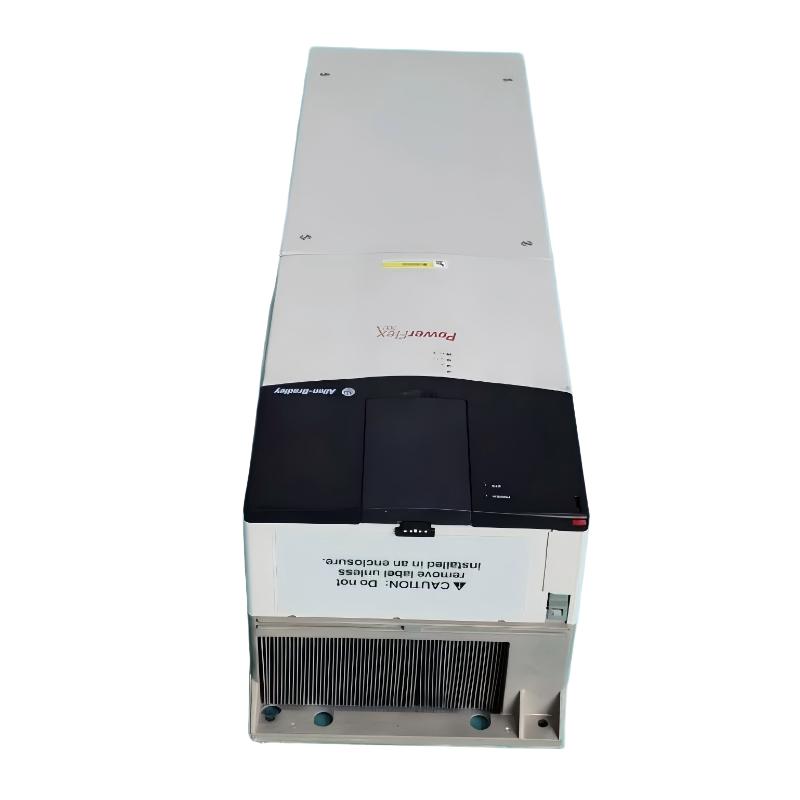
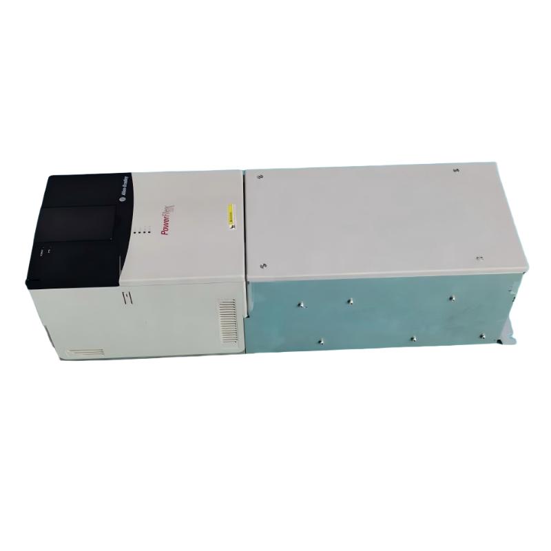
- Allen Bradley
- 20BD180A0ANNAND0
- PowerFlex AC Drive
- USA
- 1828.8 × 711.3 × 487.8 mm
- 229.07kg
- Xiamen, China
- New & In Stock
- T/T, PayPal, Western Union
- 1 Year
- 1-3 Working Days
- DHL, UPS, TNT, FedEx and EMS.
- 24-Hour Service
- COO
- 2
Our advantage

Global Logistics
We have a 10-year logistics and express cooperation agreement, so our products can be shipped to any place in the world.

Brand new and original
Our products are imported in bulk from the place of origin. Because of the cooperative relationship, our products are all original and 100% new.

24-hour service
We provide 7*24 hours service to our customers. We will be there whenever you need us.

Price advantage
All our products are priced very favorably because we have our own warehouse and supply.
| Company Information | |||
| [email protected] | |||
| Mobile | +8615980777398 | ||
| +8615980777398 | |||
| 15980777398 |
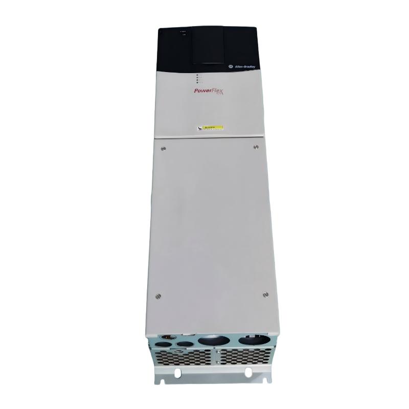
Allen-Bradley 20BD180A0ANNAND0 AC Drive: Technical Specifications, Product Description, Applications, Advantages, and Related Models
1. Product Overview
The Allen-Bradley 20BD180A0ANNAND0 is an industrial variable-frequency AC drive in the PowerFlex 700 series. It is designed to control the speed and operation of three-phase AC motors used in manufacturing equipment, material-handling systems, pumps, fans, and other industrial machinery.
A variable-frequency drive adjusts the frequency and voltage supplied to a motor, allowing the motor to run at a speed appropriate for the process. This can improve operating flexibility, provide smoother acceleration and deceleration, and reduce mechanical stress associated with direct-on-line starting.
The 20BD180A0ANNAND0 belongs to the high-current range of the PowerFlex 700 family. Its closely related 180 A configuration is associated with a 480 V AC, three-phase supply and a 150 HP normal-duty rating. However, exact electrical ratings and installed options should be checked against the complete catalog number and the physical unit’s nameplate before the drive is specified for a new installation or replacement.
The PowerFlex 700 family supports industrial motor-control applications requiring adjustable speed, configurable control behavior and integration with external automation equipment. Its suitability for a particular machine depends on motor current, load type, overload requirements, control wiring, communication interfaces, braking needs and installation conditions.
2. Brand and Product Series
|
Item |
Specification |
|---|---|
|
Brand |
Allen-Bradley |
|
Product series |
PowerFlex 700 |
|
Product type |
Industrial variable-frequency AC drive |
|
Full catalog number |
20BD180A0ANNAND0 |
|
Input voltage |
480 V AC |
|
Input phase |
Three-phase |
|
Input frequency |
60 Hz nominal |
|
Continuous output current |
180 A, normal duty |
|
Normal-duty motor rating |
150 HP |
|
Heavy-duty motor rating |
125 HP |
|
Frame size |
Frame 6 |
|
Enclosure |
IP20 / NEMA Type 1 |
|
Conformal coating |
Included in the specified configuration |
|
Control configuration |
Vector control with 120 V I/O |
|
Human interface module |
No HIM; blank plate fitted |
|
Brake IGBT |
Not included |
|
Internal brake resistor |
Not included |
|
Feedback option |
No feedback |
|
Internal communication module |
Not included |
|
EMC filtering |
Second-environment filter configuration with common-mode choke |
|
Lifecycle status |
Discontinued |
|
Typical installation |
Protected industrial electrical cabinet |
The model number identifies a particular combination of electrical ratings, enclosure, control interface and installed options. For this reason, the full catalog number should be retained when purchasing spare parts or evaluating a replacement. A drive with the same current rating may still have different I/O voltage, communications, braking hardware or feedback capability.
3. Detailed Technical Parameters
3.1 Electrical Specifications
|
Parameter |
Specification |
|---|---|
|
Model |
20BD180A0ANNAND0 |
|
Series |
PowerFlex 700 |
|
Rated input voltage |
480 V AC |
|
Input phase |
3-phase |
|
Nominal input frequency |
60 Hz |
|
Input current |
169 A at 480 V AC, 3-phase |
|
Input apparent power |
141 kVA |
|
Continuous output current |
180 A, normal duty |
|
Normal-duty motor power |
150 HP |
|
Heavy-duty motor power |
125 HP |
|
Output phase |
3-phase |
|
Output voltage range |
0 to rated motor voltage |
|
Output voltage at 480 V-class supply |
Up to approximately 460 V AC |
|
Maximum output frequency |
Up to 420 Hz |
|
Carrier-frequency options |
2, 4, 8 and 10 kHz |
|
Rated carrier-frequency basis |
4 kHz |
|
Motor-control methods |
Sensorless vector, V/Hz and vector-control options |
|
Control I/O voltage |
120 V I/O |
|
Analog inputs |
2 |
|
Analog outputs |
2 |
|
Digital inputs |
6 |
|
Digital outputs |
3 |
|
Displacement power factor |
Approximately 0.98 across the speed range |
|
Typical rated-load efficiency |
Approximately 97.5% |
|
Internal communication module |
None |
|
Motor feedback |
None |
|
Internal brake resistor |
None |
|
Brake IGBT |
None |
|
EMC filter |
Included, with common-mode choke |
|
Enclosure rating |
IP20 / NEMA Type 1 |
3.2 Overload and Control Performance
|
Parameter |
Specification |
|---|---|
|
Normal-duty continuous output current |
180 A |
|
Heavy-duty output current, 1 minute |
234 A |
|
Heavy-duty output current, 3 seconds |
312 A |
|
AC input overvoltage trip |
Approximately 570 V AC |
|
AC input undervoltage trip |
Approximately 280 V AC |
|
DC bus nominal voltage |
Approximately 648 V DC |
|
DC bus overvoltage trip |
Approximately 810 V DC |
|
DC bus undervoltage shutdown |
Approximately 305 V DC |
|
Programmable current limit |
Approximately 20–160% of rated output current |
|
Acceleration and deceleration ramps |
Two independently programmable ramps |
|
Programmable ramp-time range |
0–3600 seconds |
|
Ramp-time increment |
0.1 second |
|
Stop modes |
Coast, DC braking, fast braking, ramp-to-stop, S-curve and other supported modes |
|
Power ride-through |
Approximately 15 ms at full load |
|
Logic-control ride-through |
Approximately 0.5 second minimum; 2 seconds typical |
|
Short-circuit rating |
Up to 200,000 A symmetrical when the installation meets applicable protective-device requirements |
|
Typical IP20 internal power loss |
Approximately 493 W at 480 V and 150 HP normal duty |
|
Typical sound level |
Approximately 72 dB for Frame 6 under the specified fan-airflow condition |
|
Maximum altitude without derating |
Approximately 1,000 m |
|
Operating temperature |
Typically 0–50°C for applicable Frame 6 IP20 ratings |
|
Relative humidity |
5–95%, non-condensing |
|
Storage temperature |
Down to approximately −40°C |
The drive’s current ratings and overload limits serve different purposes. The 180 A rating is the continuous normal-duty output rating, while the higher overload values apply only for specified durations and operating conditions. The correct settings depend on the motor nameplate, load profile, acceleration time, cooling conditions and installation design.
3.3 Dimensions and Weight
Physical dimensions are especially important for replacement projects because the drive must fit the existing cabinet and allow sufficient cooling airflow. The product data distinguishes the standard IP20 drive from a separate IP54/NEMA Type 12 standalone enclosure.
|
Physical parameter |
Specification |
|---|---|
|
Model |
20BD180A0ANNAND0 |
|
Frame size |
Frame 6 |
|
Standard drive enclosure |
IP20 / NEMA Type 1 |
|
Exact IP20 drive height |
Confirm from the model-specific dimensional drawing |
|
Exact IP20 drive width |
Confirm from the model-specific dimensional drawing |
|
Exact IP20 drive depth |
Confirm from the model-specific dimensional drawing |
|
Exact IP20 drive net weight |
Not confirmed here |
|
Separate IP54 standalone assembly height |
Approximately 1828.8 mm |
|
Separate IP54 standalone assembly width |
Approximately 711.3 mm |
|
Separate IP54 standalone assembly depth |
Approximately 487.8 mm |
|
Separate IP54 standalone assembly weight |
Approximately 229.07 kg, including the drive and packaging |
|
Installation orientation |
Follow the applicable dimensional drawing |
|
Required ventilation |
Follow the installation instructions for Frame 6 |
|
Mounting details |
Verify mounting holes and clearances against the actual configuration |
Important dimensional clarification: The 1828.8 × 711.3 × 487.8 mm measurements and 229.07 kg weight refer to a separate IP54/NEMA Type 12 standalone assembly, not the standard IP20 drive alone. They must not be used as the dimensions or net weight of the bare IP20 unit. For an accurate cabinet layout, shipping calculation or direct replacement, confirm the IP20 unit’s mechanical drawing and net weight for catalog number 20BD180A0ANNAND0.
4. Product Introduction
The PowerFlex 700 is an industrial AC drive family designed to regulate motor speed and torque in equipment that operates under changing production or process conditions. Instead of supplying a motor with a fixed-frequency output, the drive adjusts the output to control the motor’s operating speed.
The 20BD180A0ANNAND0 is a 480 V, three-phase drive with a continuous normal-duty output rating of 180 A. Its 150 HP normal-duty rating makes it suitable for evaluating in larger industrial motor-control systems, while its 125 HP heavy-duty rating is relevant when the application demands greater overload capability.
The drive’s vector-control capabilities can help provide responsive motor control in suitable applications. Depending on the selected control method and the machine’s characteristics, it can support controlled starting, speed adjustment and stopping. The drive’s performance depends on the motor, configuration, parameter settings and load requirements.
The model is supplied with a blank front-panel plate rather than an installed human-interface module. Commissioning and parameter adjustment therefore need to be performed using a compatible interface or other supported configuration method. The specified model also has no internal communication module, so a network interface should not be assumed to be present.
The absence of an internal brake resistor and brake IGBT is another important consideration. Machines requiring rapid deceleration, frequent braking or control of high-inertia loads may need a separately engineered braking arrangement.
The drive uses an IP20/NEMA Type 1 enclosure, intended for installation in a suitable protected environment. It is not designed to be exposed directly to water, washdown spray or conductive contamination. Cabinet ventilation, wiring access and service clearance should be considered during installation.
The PowerFlex 700 20B family is discontinued. For existing machinery, it may remain a practical maintenance option where the unit is functioning correctly and repair or replacement support is available. For a new installation or major modernization, the availability of spares and the long-term support plan should be evaluated before choosing the same product family.
5. Main Product Advantages
5.1 High Output-Current Capacity
The 180 A continuous normal-duty rating supports motor applications that require substantial current capacity. This can be useful for larger industrial conveyors, pumps, fans, mixers and processing equipment.
The current rating should always be checked against the motor nameplate. Horsepower alone does not establish suitability, because motor efficiency, power factor, load torque, starting requirements and operating conditions can all affect current demand.
5.2 Adjustable Motor Speed
The drive allows the motor to operate at a speed appropriate for the process. This can improve production flexibility where equipment needs multiple operating speeds or where process demand varies during the working cycle.
In suitable fan and centrifugal-pump applications, reducing motor speed may also lower energy consumption. Actual savings depend on the load curve, required output, operating hours and overall system efficiency.
5.3 Controlled Starting and Stopping
Programmable acceleration and deceleration ramps allow the machine to reach operating speed gradually and stop in a controlled manner. This can reduce mechanical shock on belts, couplings, gearboxes and transported materials.
A suitable ramp must be chosen for the load. Very short deceleration times may cause DC-bus overvoltage, while overly long ramps may delay production or fail to meet the machine’s operating requirements.
5.4 Vector-Control Capability
Vector-control methods can provide improved torque and speed response compared with basic V/Hz control in suitable applications. This is useful where the load changes during operation or where the motor must respond consistently to changing process conditions.
The model is specified without feedback. Applications requiring encoder-based speed regulation, accurate low-speed operation or tightly synchronized motors should therefore be reviewed carefully before selection.
5.5 Built-In Monitoring and Protection Functions
The PowerFlex 700 family supports drive monitoring and protective functions that can help identify abnormal electrical or operating conditions. Appropriate settings can help protect the drive and motor from continued operation outside configured limits.
Protection performance depends on correct commissioning. Motor nameplate data, current limits, thermal settings, ramp times and upstream protection must all be configured appropriately. The drive does not replace required machine-safety systems, guards or electrical isolation.
5.6 Flexible External Control
The drive’s analog and digital I/O can be used for external speed references, run commands, status signals and control interlocks. This makes it possible to integrate the drive into a range of industrial control arrangements.
However, this particular configuration uses 120 V I/O and has no internal communication module. PLC output voltage and communication requirements should be checked before wiring or specifying additional interfaces.
5.7 Industrial Cabinet Integration
The IP20/NEMA Type 1 configuration can be installed inside a suitable industrial electrical cabinet. A well-designed cabinet protects the drive from unsuitable environmental conditions and provides organized wiring, airflow and maintenance access.
When replacing an existing unit, the mechanical layout must be verified. Two drives with the same electrical rating can have different mounting dimensions, terminal arrangements or installed options.
5.8 Practical Maintenance of Existing Systems
For an existing machine already designed around the PowerFlex 700 family, retaining a compatible drive may reduce the amount of engineering required for wiring and parameter migration.
Because the product family is discontinued, maintenance planning should include spare-drive availability, repair options, compatible accessories and the risk of production downtime if the installed unit fails.
6. Typical Industrial Applications
6.1 Conveyor Systems
Industrial conveyors often require controlled acceleration to avoid product movement, belt shock and unnecessary stress on gearboxes. A drive can provide adjustable belt speed and a more controlled start-and-stop profile.
For heavily loaded conveyors, the motor and drive should be selected based on starting torque, loaded-start conditions, belt tension and the mechanical characteristics of the conveyor. If the conveyor has a vertical section or a high-inertia load, braking and safety requirements require additional review.
6.2 Pumps and Fluid-Handling Systems
The drive can be considered for suitable industrial pumping applications where flow demand varies. Adjustable speed allows the pump motor to respond to changes in system demand instead of always running at full speed.
Energy savings are possible in suitable centrifugal-pump systems, but they are not guaranteed for every pump type or process. Minimum-flow requirements, pressure control, motor cooling and the pump manufacturer’s permitted operating range must be taken into account.
6.3 Fans and Ventilation Equipment
Industrial fans often operate under variable airflow requirements. A drive can adjust fan speed to help match the airflow to the actual process demand.
In suitable variable-torque fan applications, lower speed can reduce energy consumption. The final operating range must remain within the permitted speed limits of the motor, fan, bearings and associated mechanical components.
6.4 Mixers and Agitators
Mixers and agitators may require different speeds during filling, mixing, holding and unloading. A variable-frequency drive can provide adjustable speed settings and controlled acceleration.
The load on a mixer can change significantly with the material’s viscosity, quantity and temperature. The motor and drive should be sized for the most demanding operating condition rather than the average load.
6.5 Production and Processing Lines
Production lines may use variable-speed drives on transfer equipment, feeders, processing machines and auxiliary machinery. Controlled speed changes can help improve coordination between equipment stages.
If the process requires encoder feedback, synchronized speed control or network-based commands, the exact configuration must be checked. This model does not include an internal communication module or feedback option as specified.
6.6 General-Purpose Industrial Machinery
The drive can be evaluated for other three-phase AC motor applications where the voltage, current rating, overload capability and control interface match the equipment requirements.
The final selection should account for motor current, duty cycle, stopping requirements, environmental conditions, cable length, upstream protection and the machine’s safety architecture.
7. Five Related Models in the Same Series or Product Family
The following models are useful comparison candidates within the PowerFlex 700 family. Similar current ratings do not guarantee that the options, control wiring or communications are identical.
|
Model |
Series |
Main parameters |
Dimensions and weight |
|---|---|---|---|
|
20BD180A0ANNAND0 |
PowerFlex 700 |
480 V AC, 3-phase, 180 A, 150 HP normal duty, 125 HP heavy duty, IP20 / Type 1, 120 V I/O, no feedback, no internal communication module |
Frame 6; exact IP20 dimensions and net weight should be confirmed from the matching drawing |
|
20BD180A0ANNANC0 |
PowerFlex 700 |
480 V AC, 3-phase, 180 A, 150 HP normal duty, 125 HP heavy duty; verify option differences before substitution |
Frame 6-class configuration; confirm the full model drawing and weight |
|
20BD180A0AYNANN0 |
PowerFlex 700 |
480 V-class, 180 A model; option set differs from the target model, so confirm I/O, feedback and braking details |
Confirm the exact mechanical drawing and net weight |
|
20BD156A3ANNAND0 |
PowerFlex 700 |
480 V-class, 3-phase, 156 A class; lower current capacity than the target model |
Confirm the exact mechanical drawing and net weight |
|
20BD156A3ANNACA0 |
PowerFlex 700 |
480 V-class, 3-phase, 156 A class; alternate option configuration; verify communications and I/O |
Confirm the exact mechanical drawing and net weight |
How to Select a Related Model
– For a closest match: Start with another 180 A PowerFlex 700 configuration and compare the full catalog number, control voltage, feedback, communications and braking features.
– For a different control architecture: Check whether the machine needs 120 V I/O, 24 V I/O, a network interface or encoder feedback. The correct option set is as important as the current rating.
– For a lower-current alternative: A 156 A model should only be considered when the motor’s full-load current and overload requirements are compatible with the lower drive rating.
– For a direct replacement: Confirm the motor nameplate, drive parameters, terminal wiring, mounting dimensions and required protection settings before installation.
These models are comparison candidates rather than guaranteed drop-in replacements. Final compatibility depends on the exact installed hardware and the machine’s electrical and mechanical requirements.
8. Five Other Popular Models from the Same Brand
The following models cover other commonly used industrial AC-drive product families. The smaller PowerFlex 525 units are intended for lower-current applications, while the PowerFlex 753 and 755 families are more relevant when evaluating a larger industrial drive modernization.
|
Model |
Series |
Main parameters |
Dimensions and weight |
|---|---|---|---|
|
25B-D6P0N104 |
PowerFlex 525 |
Compact 480 V-class drive; approximately 6 A output-current class; intended for smaller motor applications |
Compact frame; confirm exact height, width, depth and net weight |
|
25B-D010N104 |
PowerFlex 525 |
Compact 480 V-class drive; approximately 10 A output-current class; adjustable-speed motor control |
Compact frame; confirm exact height, width, depth and net weight |
|
25B-D017N104 |
PowerFlex 525 |
Compact 480 V-class drive; approximately 17 A output-current class; suitable for compatible smaller industrial motors |
Compact frame; confirm exact height, width, depth and net weight |
|
20F1ANC170JA0NNNNN |
PowerFlex 753 |
Industrial PowerFlex 750-series drive; intended for higher-power applications; verify exact voltage, output current and options |
Frame- and option-dependent; confirm the model-specific drawing and net weight |
|
20G1ANC260JA0NNNNN |
PowerFlex 755 |
Industrial PowerFlex 750-series drive; advanced motor-control platform; verify exact voltage, current and installed options |
Frame- and option-dependent; confirm the model-specific drawing and net weight |
The PowerFlex 525 models are not direct electrical replacements for a 180 A PowerFlex 700. Their current capacities are substantially lower. The PowerFlex 753 and PowerFlex 755 families may be more appropriate candidates for a modernization, but the exact catalog number, current rating, overload duty, communication interfaces, braking requirements and dimensions must be checked before selection.
The dimensions and weights of these alternatives are not estimated from their series names alone. Frame size, voltage class, enclosure and installed options can significantly affect physical size and weight.
9. Comparison of the Target Model and Related Options
|
Comparison item |
20BD180A0ANNAND0 |
20BD180A0ANNANC0 |
20BD180A0AYNANN0 |
20BD156A3ANNAND0 |
|---|---|---|---|---|
|
Product series |
PowerFlex 700 |
PowerFlex 700 |
PowerFlex 700 |
PowerFlex 700 |
|
Voltage class |
480 V AC |
480 V AC class |
480 V class |
480 V class |
|
Continuous output current |
180 A |
180 A class |
180 A class |
156 A class |
|
Normal-duty motor rating |
150 HP |
150 HP class |
Confirm exact configuration |
Approximately 125 HP class |
|
Heavy-duty motor rating |
125 HP |
125 HP class |
Confirm exact configuration |
Confirm exact configuration |
|
Enclosure |
IP20 / Type 1 |
Confirm exact configuration |
Confirm exact configuration |
Confirm exact configuration |
|
Control interface |
Vector control with 120 V I/O |
Verify complete configuration |
Verify complete configuration |
Verify complete configuration |
|
Feedback |
None |
Verify complete configuration |
Verify complete configuration |
Verify complete configuration |
|
Internal communication module |
None |
Verify complete configuration |
Verify complete configuration |
Verify complete configuration |
|
Internal brake resistor |
None |
Verify complete configuration |
Verify complete configuration |
Verify complete configuration |
|
IP20 dimensions |
Confirm exact drawing |
Confirm exact drawing |
Confirm exact drawing |
Confirm exact drawing |
|
Net weight |
Confirm exact drawing |
Confirm exact drawing |
Confirm exact drawing |
Confirm exact drawing |
10. Installation and Commissioning Considerations
10.1 Supply Voltage and Electrical Protection
Confirm that the incoming supply is compatible with the drive’s 480 V AC, three-phase rating. Upstream fuses or circuit breakers should be selected in accordance with the drive’s installation requirements, the available fault current and applicable electrical regulations.
Grounding, conductor sizing and separation of power and control wiring should follow the applicable instructions. Incorrect grounding or unsuitable wiring can cause interference, nuisance trips or equipment damage.
10.2 Motor Compatibility
Check the motor’s rated voltage, full-load current, horsepower, base frequency and required operating range. Enter the motor nameplate data correctly during commissioning.
The drive’s current and overload capabilities must be compatible with the actual load. If the motor operates under frequent overload, high starting torque or rapid acceleration, the duty rating should be reviewed before the drive is selected.
10.3 Cabinet Space and Cooling
The IP20 drive should be installed in a protected electrical cabinet or suitable equipment area. The panel design must account for heat dissipation, airflow, cable routing, maintenance access and the required mounting clearances.
Do not use the dimensions of a separate IP54/NEMA Type 12 standalone assembly as the physical dimensions of the IP20 drive. Confirm the correct drawing for the exact Frame 6 configuration before cutting panels or preparing mounting hardware.
10.4 Control Wiring and PLC Integration
The target model is specified with 120 V I/O. Verify the voltage and electrical characteristics of PLC outputs, relays, pushbuttons and interlocks before connecting them to the drive.
Since the configuration does not include an internal communication module, determine how the system will provide remote commands, status monitoring or network-based diagnostics if those functions are required.
10.5 Braking Requirements
The drive does not include an internal brake resistor or brake IGBT. Applications requiring rapid stopping, frequent deceleration or handling of high-inertia loads may require a separately engineered braking solution.
The braking arrangement must be sized for the load’s regenerative energy and duty cycle. For vertical movement or hazardous machinery, mechanical holding and safety functions must also be addressed independently.
10.6 Environmental Conditions
The IP20/NEMA Type 1 enclosure is intended for protected installations. It should not be exposed directly to water, washdown spray or unsuitable conductive contamination.
Confirm the ambient temperature, humidity, altitude and pollution conditions. Additional enclosure protection may be required where the environment exceeds the drive’s intended conditions.
10.7 Maintenance and Lifecycle Planning
The PowerFlex 700 20B family is discontinued. For an existing installation, assess spare-drive availability, repair options, the condition of installed components and the cost of unexpected downtime.
Before replacing a drive, record the existing parameters, terminal connections, control logic, network settings and fault history where possible. The replacement should be commissioned under controlled conditions, with protective functions and machine interlocks tested before returning the equipment to production.
11. Product Summary
The Allen-Bradley 20BD180A0ANNAND0 PowerFlex 700 is a 480 V AC, three-phase industrial variable-frequency drive with a continuous output rating of 180 A. Its specified configuration is rated at 150 HP normal duty and 125 HP heavy duty, uses vector control with 120 V I/O, and has an IP20/NEMA Type 1 enclosure.
Its main strengths include adjustable motor speed, programmable acceleration and deceleration, industrial motor-control capability and support for a range of production and process applications. The lack of an internal communication module, feedback option, brake IGBT and brake resistor must be considered when integrating the drive into a machine.
For a replacement or new installation, the most important checks are the motor’s actual current requirement, the drive’s duty rating, the I/O voltage, the required communications and braking functions, and the physical mounting arrangement. Because the PowerFlex 700 20B family is discontinued, spare-part availability and future maintenance should also form part of the selection decision.
Recommended selection approach: Use the complete catalog number 20BD180A0ANNAND0 as the reference, verify the exact mechanical drawing and net weight, and compare alternatives against the motor’s electrical requirements and the machine’s control architecture before making a final purchase decision.