
NewsNEWCENTER
Featured products
Contact Us
Allen Bradley 1606-XLS180B Power Supply Installation Guide
2026-09-23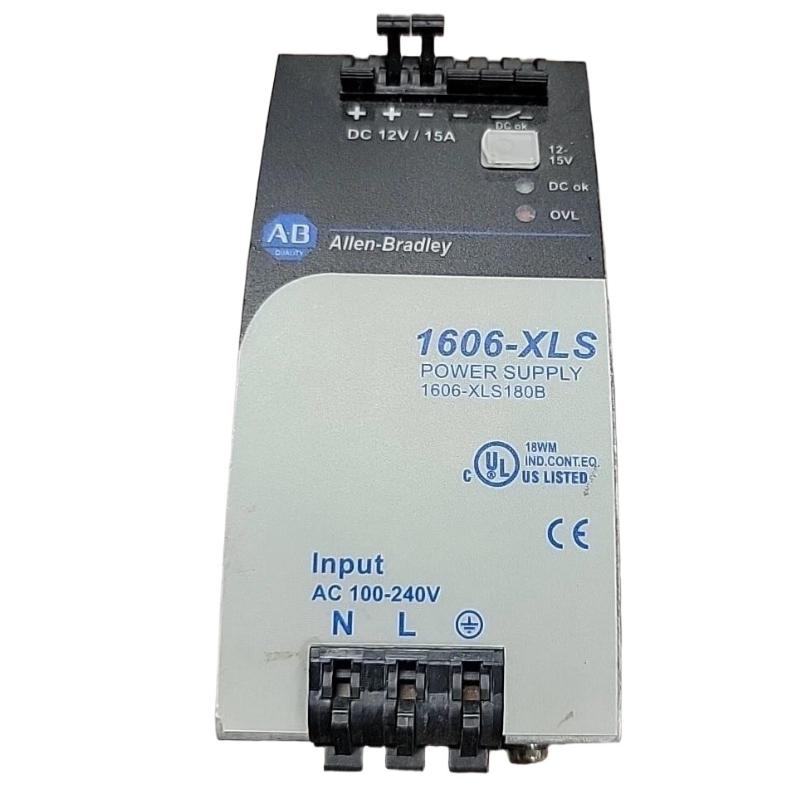
The Allen Bradley 1606-XLS180B power supply is installed as part of an industrial control cabinet power architecture, where correct input wiring, protective grounding, DC output distribution, load management, and thermal conditions are essential for reliable operation. The installation should be completed with the exact terminal arrangement and electrical characteristics verified against the documentation applicable to the specific 1606-XLS180B unit.
Allen Bradley 1606-XLS180B Power Supply Installation Overview
The 1606-XLS180B belongs to the Allen Bradley 1606-XLS family of industrial power supplies. Its role is to convert the available input power into regulated DC power for automation and control equipment.
In a typical control cabinet, the power supply forms the link between the incoming electrical distribution system and the DC control circuit.
Incoming Power
      |
      v
Circuit Protection / Isolation
      |
      v
Allen Bradley 1606-XLS180B
      |
      v
DC Power Distribution
      |
      +---- PLC / Controller
      +---- I/O Modules
      +---- Sensors
      +---- Relays
      +---- Communication Equipment
Because a power supply can affect multiple downstream devices simultaneously, installation quality is important. Loose terminals, excessive loading, poor ventilation, incorrect polarity, or unsuitable input conditions can create faults that appear elsewhere in the control system.
Allen Bradley 1606-XLS180B Power Supply Function in an Industrial Control System
The 1606-XLS180B provides DC power to connected control equipment. It does not normally execute PLC application logic; instead, it supports the electrical infrastructure required by controllers, I/O devices, sensors, relays, and other DC loads.
- Provides regulated DC power for industrial automation equipment.
- Supports the power requirements of control circuits.
- Provides a centralized DC supply point inside the cabinet.
- Supports reliable operation of connected automation components.
- Allows DC loads to be organized into a controlled power distribution architecture.
Allen Bradley 1606-XLS180B Installation Preparation
Before mounting the 1606-XLS180B, review the cabinet power architecture and determine the expected electrical load. The input supply and downstream DC circuits should be identified before any wiring is performed.
- Confirm the complete model number: 1606-XLS180B.
- Inspect the power supply for physical or shipping damage.
- Verify the available input power.
- Confirm the required DC output characteristics for connected loads.
- Calculate or estimate the expected continuous DC load.
- Check cabinet ventilation and ambient conditions.
- Prepare suitable upstream circuit protection and isolation.
- Prepare the required protective earth connection.
- Keep power wiring appropriately separated from sensitive communication wiring.
Allen Bradley 1606-XLS180B Mounting and Panel Layout
The power supply should be mounted securely in an appropriate industrial control enclosure. The mounting position should provide adequate airflow and allow technicians to inspect the wiring and terminals without unnecessary disassembly.
When multiple power supplies, drives, contactors, or other heat-producing devices are installed in the same cabinet, consider their combined thermal effect. Do not obstruct ventilation paths around the 1606-XLS180B.
- Install the unit on the specified mounting surface.
- Maintain the required clearance around the equipment.
- Avoid blocking ventilation openings.
- Keep high-current power conductors organized and secure.
- Provide practical access for maintenance and voltage measurement.
Allen Bradley 1606-XLS180B Wiring and Interface Connections
Before wiring, isolate the incoming power according to the site’s approved electrical safety procedure. The exact terminal designations and wiring arrangement must be verified from the documentation applicable to the 1606-XLS180B installation.
Incoming AC
    |
    v
[ Protective Device ]
    |
    v
[ 1606-XLS180B ]
    |
    +---- DC Positive ----> DC Loads
    |
    +---- DC Negative ----> DC Loads
    |
    +---- Protective Earth / Ground
Input and output conductors should be correctly identified and securely terminated. DC polarity should be checked before connecting sensitive automation devices. Never assume the terminal arrangement of one 1606-XLS model is identical to another model without verification.
Allen Bradley 1606-XLS180B Power Supply Setup
Once the mechanical installation and wiring have been completed, inspect the entire power circuit before energization.
- Verify incoming power wiring.
- Verify protective earth and cabinet bonding.
- Verify DC output polarity.
- Check terminal tightness.
- Confirm downstream loads are compatible with the power system.
- Ensure no exposed conductor can contact an adjacent terminal.
- Apply power using the approved startup sequence.
- Check the power supply operating status.
- Measure the DC output.
- Enable downstream loads progressively.
Allen Bradley 1606-XLS180B Commissioning Procedure
Commissioning should verify the power supply first under controlled conditions and then under normal system load.
Mechanical Inspection
        |
        v
Input Wiring Verification
        |
        v
Grounding Verification
        |
        v
Power-On
        |
        v
DC Output Measurement
        |
        v
Load Connection
        |
        v
Loaded Output Measurement
        |
        v
Control System Functional Test
        |
        v
Final Inspection
If the DC output is abnormal, stop the commissioning sequence and determine whether the cause is the incoming supply, wiring, load, distribution circuit, environmental condition, or power supply itself.
Allen Bradley 1606-XLS180B Installation Validation
After commissioning, verify that the power supply and downstream distribution system operate consistently under normal cabinet conditions.
- Mechanical mounting is secure.
- Input connections are correctly terminated.
- Protective earth is correctly connected.
- DC polarity has been verified.
- Connected loads are appropriate for the power architecture.
- DC voltage remains stable during normal operation.
- There is no abnormal heating or visible damage.
- Cabinet airflow is adequate.
- Downstream control equipment operates without unexplained power interruptions.
Allen Bradley 1606-XLS180B Field Commissioning Case
Representative example: A new automation cabinet is commissioned with the 1606-XLS180B supplying several control devices. The power supply operates normally without the full load, but a downstream controller experiences an undervoltage condition after additional devices are enabled.
Initial Test:
Power supply operating normally

Additional Loads:
Several DC devices enabled

Observed:
Controller reports low-voltage condition

Diagnostic Checks:
1. Measure voltage at power supply
2. Measure voltage at controller
3. Inspect distribution terminals
4. Check total DC load
5. Inspect cable and connector condition

Diagnostic Direction:
Investigate downstream distribution and load demand
This representative example demonstrates why commissioning should include measurements at the actual load. A normal voltage reading directly at the power supply does not automatically prove that every downstream device receives the same voltage.
Allen Bradley 1606-XLS180B Installation FAQ
What is the Allen Bradley 1606-XLS180B?
The Allen Bradley 1606-XLS180B is an industrial power supply used to provide regulated DC power for automation and control equipment.
Where is the 1606-XLS180B used?
It is intended for industrial control and automation installations where a suitable DC power source is required for connected control equipment.
What should be checked before installation?
Verify the complete model number, input power, output requirements, load demand, grounding, circuit protection, terminal arrangement, mounting conditions, and cabinet ventilation.
Why should the output be checked at the downstream equipment?
Voltage losses can occur in distribution cables, connectors, protection devices, or terminal connections. Checking only the power-supply terminals may therefore miss a problem in the downstream circuit.
Can the 1606-XLS180B be installed in the same cabinet as other automation equipment?
Yes, provided the cabinet layout, electrical separation, mounting, ventilation, grounding, and environmental requirements are properly addressed.
Allen Bradley 1606-XLS180B Technical Summary
The Allen Bradley 1606-XLS180B power supply should be integrated into the control cabinet as part of a complete power distribution system. Reliable installation depends on correct input wiring, grounding, DC distribution, load assessment, thermal management, and controlled commissioning. Before energizing or replacing the unit, technicians should verify the exact electrical and terminal information applicable to the installation.