
NewsNEWCENTER
Featured products
Contact Us
Allen-Bradley 1336F-MCB-SP1J Drive Control Board Installation Guide
2026-06-22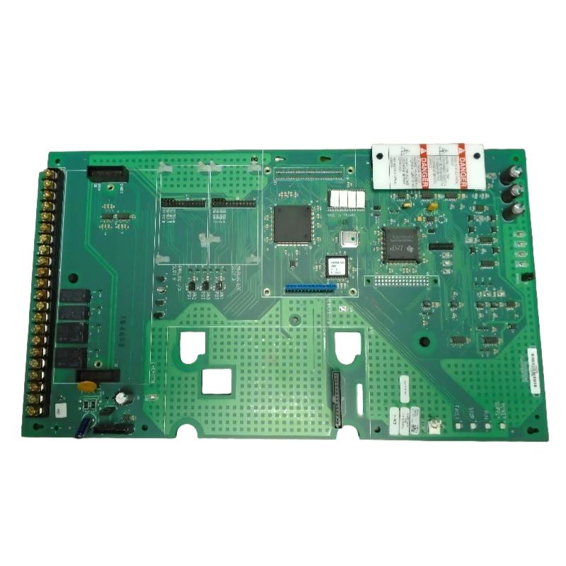
Table of Contents
- Installation Overview of 1336F-MCB-SP1J Control Board
- Role in 1336F Series Drive Control Architecture
- Pre-Installation Safety & System Isolation
- Mechanical Installation & Connector Alignment
- Signal Interface & Ribbon Cable Rules
- Control Power Supply Stability Requirements
- Commissioning & Logic Verification
- FAQs on 1336F-MCB-SP1J Installation
- Engineering Summary & Field Practices
Installation Overview of 1336F-MCB-SP1J Control Board
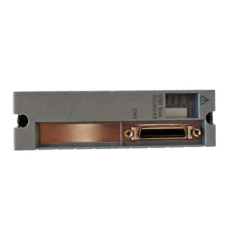
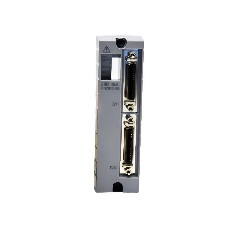
The Allen-Bradley 1336F-MCB-SP1J is the main control board used in 1336F series VFD systems. It manages drive logic, PWM generation, fault monitoring, and communication with external control systems. Proper installation is critical for stable inverter operation.
Role in 1336F Series Drive Control Architecture
This board acts as the central processor of the VFD system, coordinating between user commands, feedback loops, and inverter switching stages. It ensures correct sequencing of start/stop operations and protection logic execution.
Pre-Installation Safety & System Isolation
- Disconnect all power sources including DC bus supply
- Verify capacitor discharge before handling control board
- Use ESD protection equipment during installation
- Confirm correct board revision (SP1J compatibility check)
Mechanical Installation & Connector Alignment
- Align control board with designated mounting rails
- Insert ribbon connectors carefully without bending pins
- Ensure full seating of backplane interface connectors
- Secure board to prevent vibration-induced loosening
Field observation shows that incomplete connector seating is a common cause of “no run” conditions after installation.
Signal Interface & Ribbon Cable Rules
- Ensure correct orientation of all ribbon cables
- Avoid excessive bending or twisting of flat cables
- Keep control wiring separated from power stage conductors
- Check continuity of all feedback signal paths
CONTROL_INSTALL_CHECK /MODEL=1336F-MCB-SP1J /RIBBON_VERIFY /SIGNAL_PATH_TEST /LOGIC_INIT
Control Power Supply Stability Requirements
- Verify stable low-voltage supply before energizing system
- Ensure no ripple or undervoltage on logic supply rail
- Check decoupling capacitors on backplane power distribution
In one commissioning case, unstable auxiliary supply caused repeated startup failures until power filtering was corrected.
Commissioning & Logic Verification
- Power up system in no-load condition
- Verify keypad and external control command response
- Check drive state transitions (READY → RUN)
- Monitor fault register status during startup
- Perform low-speed motor test under controlled load
FAQs on 1336F-MCB-SP1J Installation
Can the drive operate if ribbon cable is partially connected?
No. Partial connection can result in missing logic signals and complete non-start conditions.
Is ESD protection really necessary for installation?
Yes. The control board contains sensitive CMOS logic that can be damaged by static discharge.
What is the most common installation error?
Incorrect connector seating and improper ribbon cable alignment are the most frequent issues.
Engineering Summary & Field Practices
The Allen-Bradley 1336F-MCB-SP1J control board is the central intelligence unit of the 1336F drive system. Proper installation requires strict attention to connector integrity, signal routing, and power stability. Field experience confirms that most drive “no-run” issues originate from installation errors rather than component failure.