
NewsNEWCENTER
Featured products
Contact Us
Allen-Bradley 1203-SM1 SLC to SCANport Communication Module Installation Guide
2026-06-15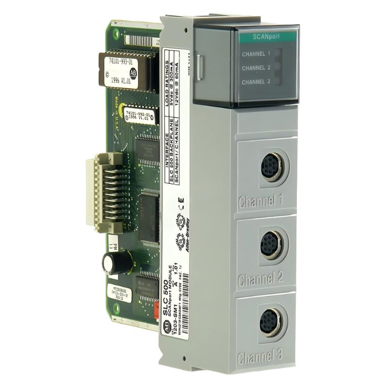
Table of Contents
- Installation Overview of 1203-SM1 SLC to SCANport Module
- Role in SLC 500 Rack Communication Architecture
- Pre-Installation Checks & Hardware Preparation
- Rack Installation & Mechanical Seating
- SCANport Cabling & Drive Connection Rules
- DIP Switch Configuration & System Setup
- Commissioning & Drive Communication Test
- FAQs on 1203-SM1 Installation
- Engineering Summary
Installation Overview of 1203-SM1 SLC to SCANport Module
The Allen-Bradley 1203-SM1 SLC to SCANport communication module is used to integrate SLC 500 PLC systems with SCANport-based drives. In field applications, it acts as a bridge between the SLC rack backplane and up to three SCANport devices, enabling centralized motor control and feedback monitoring.
Role in SLC 500 Rack Communication Architecture
The 1203-SM1 module allows a single SLC processor to control multiple SCANport devices through a dedicated interface. Each channel supports independent drive communication, making it widely used in legacy motor control systems where modern Ethernet-based integration is not available.
Pre-Installation Checks & Hardware Preparation
- Verify SLC rack compatibility (4, 7, 10, or 13-slot chassis)
- Confirm SCANport drive compatibility and firmware version
- Check enclosure depth (minimum 200 mm required)
- Inspect SCANport cables for shielding integrity
- Record DIP switch settings before installation
Rack Installation & Mechanical Seating
- Power down SLC rack and apply LOTO procedure
- Insert module firmly into backplane connector
- Ensure locking tabs fully engage with chassis rails
- Verify physical alignment to avoid backplane damage
In one commissioning case, improper seating caused intermittent scan failures that mimicked drive communication faults.
SCANport Cabling & Drive Connection Rules
- Use approved Allen-Bradley SCANport cables only
- Maintain maximum 10-meter distance per channel
- Avoid routing cables near motor power or VFD lines
- Each module supports up to three SCANport devices
Field observation shows that EMI from adjacent VFD wiring is a major cause of intermittent drive dropout in SCANport systems.
DIP Switch Configuration & System Setup
Correct DIP switch configuration is essential for stable operation:
- Set node address before powering the system
- Match configuration with SLC processor addressing scheme
- Record settings for future module replacement
SLC_SM1_CONFIG /MODEL=1203-SM1 /DIP_READ /SCANPORT_ENABLE /CHANNEL_INIT
Commissioning & Drive Communication Test
- Power up SLC rack and verify module status LEDs
- Check SCANport channel activity indicators
- Test each drive for start/stop control response
- Verify feedback signals in RSLogix 500 environment
- Perform full load motor test under operational conditions
FAQs on 1203-SM1 Installation
How many drives can the 1203-SM1 support?
Up to three SCANport devices, one per channel, depending on system configuration.
Can SCANport cables be replaced during operation?
Yes, but disconnecting a live channel may cause drive faults unless configured otherwise.
What is the most common installation mistake?
Poor cable routing near power lines and incorrect DIP switch configuration are the most frequent issues.
Engineering Summary
The Allen-Bradley 1203-SM1 SLC to SCANport communication module remains a critical interface in legacy SLC 500 systems. Proper installation requires careful attention to rack seating, SCANport cabling rules, DIP switch configuration, and electromagnetic compatibility. Field experience shows that most communication issues originate from installation practices rather than module hardware failure.