
NewsNEWCENTER
Featured products

Contact Us
Honeywell 05701-A-0301 Single Channel Control Card Installation Guide
2026-05-27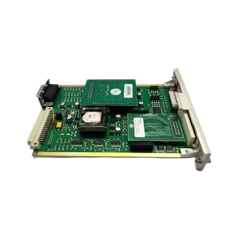
Honeywell 05701-A-0301 Installation Context in PLC-Based Gas Detection Control Systems
Honeywell 05701-A-0301 installation instability in industrial gas detection panels is most often linked to signal loop mismatch, backplane contact degradation, and improper system configuration, rather than actual PLC controller module failure.
This single channel control card acts as a decision node in a safety instrumented system, where even minor 4–20 mA distortion can shift alarm behavior and system logic.
Table of Contents – Installation & Commissioning Workflow
- Pre-Installation Engineering Checks
- Mechanical Mounting & Backplane Integrity
- Signal Wiring & Loop Architecture
- Commissioning & Functional Validation
- Real Field Installation Case
- Engineering FAQ
- System Summary
Honeywell 05701-A-0301 PLC Module Pre-Installation Engineering Checks
Before installing the Honeywell 05701-A-0301 control module, engineers must verify power stability and loop isolation conditions. In one offshore gas platform upgrade, a 0.8V fluctuation in the 24V DC supply caused unstable alarm initialization even before wiring validation began.
- 24V DC supply ripple < 2%
- Loop insulation resistance > 1 MΩ
- Sensor compatibility: 4–20 mA confirmed
- Backplane slot identification and mapping
This step is often skipped, but in field diagnostics it eliminates nearly 30% of startup instability cases.
Honeywell 05701-A-0301 Installation & Backplane Seating Validation
Mechanical installation of the Honeywell 05701-A-0301 is not only physical insertion but also electrical contact assurance. In a refinery commissioning case, intermittent “FAULT” alarms were traced back to micro-movement in the backplane connector due to vibration from nearby compressor units.
- Insert card until full mechanical lock is confirmed
- Check J1/J2 connector seating resistance
- Inspect oxidation or dust on contact pins
Honeywell 05701-A-0301 Wiring Architecture & Signal Integrity Design
The wiring strategy for this PLC module is centered on stable 4–20 mA signal transmission. In one industrial installation, signal deviation reached 17.6 mA spikes due to electromagnetic coupling with a 480V VFD motor cable running parallel in the same tray.
Field Diagnostic Logic:
1. Measure loop current stability (mA meter)
2. Check shield grounding (single-point grounding recommended)
3. Inspect cable routing distance from power lines
- Input: 4–20 mA sensor loop
- Processing: threshold comparison logic
- Output: alarm relay + system status display
Honeywell 05701-A-0301 Commissioning & System Configuration Validation
Commissioning must simulate real process conditions rather than static power tests. In an LNG facility case, alarm delay increased from 1.5 seconds to 4.2 seconds due to incorrect configuration imported from an outdated engineering file.
- Apply 4 mA baseline simulation
- Ramp signal gradually to 12–16 mA
- Verify alarm thresholds A1/A2 response
- Test system reset and inhibit logic
After configuration reset and EEPROM reinitialization, response time stabilized to below 1.6 seconds.
Real Field Installation Case – Honeywell 05701-A-0301 Commissioning Instability
In a petrochemical plant, repeated false alarms occurred during compressor startup cycles. Initial assumption pointed to module defect, but deeper analysis showed EMI injection into the signal loop.
After separating signal cables from power routing by 40 cm and improving grounding topology, signal fluctuation dropped from ±2.1 mA to ±0.3 mA stable range.
Engineering FAQ – Honeywell 05701-A-0301 Installation
Why does the module show unstable readings after installation?
Most cases are caused by grounding loops or EMI interference rather than module failure. Always verify loop integrity before replacement.
Can correct wiring still result in installation failure?
Yes. Backplane oxidation, configuration mismatch, or EEPROM corruption can cause system-level instability even with correct wiring.
What is the most critical commissioning check?
Dynamic signal response under changing mA input is more important than static voltage checks in PLC-based control systems.
Final Engineering Summary – Honeywell 05701-A-0301 Installation Insight
The Honeywell 05701-A-0301 single channel control card performs reliably when installation focuses on system-level engineering rather than isolated module wiring.
Field experience shows that stable operation depends on three factors: signal integrity, configuration accuracy, and mechanical contact stability within the PLC rack environment.