

ProductPRODUCT
Featured products
Contact Us
- Bently Nevada
- 330104-04-10-05-01-00
- 3300 XL 8 mm Proximity Probes
- USA
- 8 mm
- 0.15kg
- Xiamen, China
- New & In Stock
- T/T, PayPal, Western Union
- 1 Year
- 1-3 Working Days
- DHL, UPS, TNT, FedEx and EMS.
- 24-Hour Service
- COO
- 57
Our advantage

Global Logistics
We have a 10-year logistics and express cooperation agreement, so our products can be shipped to any place in the world.

Brand new and original
Our products are imported in bulk from the place of origin. Because of the cooperative relationship, our products are all original and 100% new.

24-hour service
We provide 7*24 hours service to our customers. We will be there whenever you need us.

Price advantage
All our products are priced very favorably because we have our own warehouse and supply.
| Company Information | |||
| [email protected] | |||
| Mobile | +8615980777398 | ||
| +8615980777398 | |||
| 15980777398 |
Complete Technical Documentation for Bently Nevada 330104-04-10-05-01-00
Product Overview
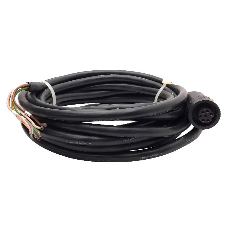
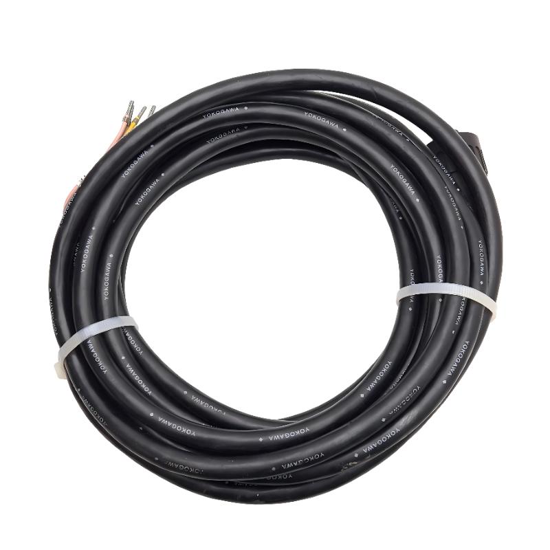
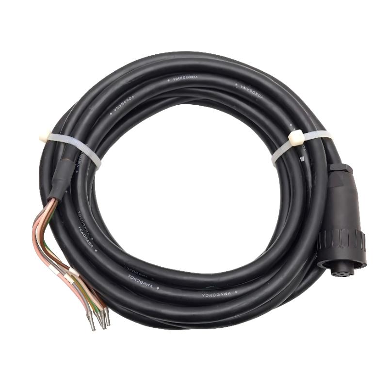
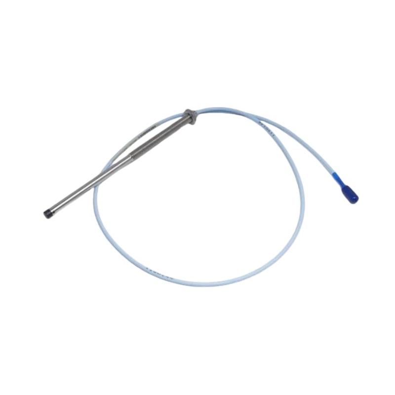
The Bently Nevada 330104-04-10-05-01-00 is a specialized 3300 XL series 8mm proximity probe system designed for non-contact displacement, vibration, and position measurement on rotating machinery. This model features a standard side-exit cable configuration with metric M10×1 threads, a very short 4mm unthreaded length, and a unique 0.5 meter integral cable terminated with flying leads (no connector). The “01-00” suffix indicates a specific cable termination and extension cable interface that allows direct hardwiring to a proximitor or junction box without the need for a mating connector.
The probe operates on the eddy current principle. A high-frequency oscillator within the proximitor drives a coil sealed inside the probe tip. As a conductive shaft surface approaches the probe tip, eddy currents are induced in that surface, opposing the magnetic field and changing the coil impedance. The proximitor demodulates this impedance change into a DC voltage that is linearly proportional to the gap distance over the full 2mm measurement range. This model achieves a linearity error of only ±0.2% of full scale and maintains stable performance across an extreme temperature range from -52°C to +177°C.
The defining characteristic of the 330104-04-10-05-01-00 is the very short 0.5 meter cable terminated with stripped and tinned flying leads. This configuration is intended for installations where the proximitor is located very close to the probe, such as inside the same junction box or within 0.5 meters of the probe mounting point. Eliminating the connector removes a potential failure point in high-vibration environments and reduces cost when connectors are unnecessary. The “01” in the suffix indicates the extension cable interface code, and “00” indicates the flying lead termination.
Product Parameters
| Parameter | Specification |
|---|---|
| Model Number | 330104-04-10-05-01-00 |
| Probe Diameter | 8 mm nominal |
| Probe Type | Standard mount (side-exit cable) |
| Thread Type | Metric M10 × 1.0 (ISO fine thread) |
| Unthreaded Length | 4 mm ±0.5 mm (distance from probe tip to first thread) |
| Overall Case Length | 50 mm (metal housing length from tip to cable entry) |
| Total Cable Length | 0.5 meter (500 mm) measured from probe tip to end of flying leads |
| Cable Termination | Flying leads (stripped and tinned wires), no connector |
| Lead Length (stripped portion) | 50 mm ±5 mm (insulation removed, wires tinned) |
| Lead Wire Color Coding | Center conductor: White; Shield: Black with white stripe |
| Cable Type | Coaxial, single shield, fluid-resistant jacket, no outer armor on this variant |
| Cable Outer Diameter | 4.0 mm ±0.2 mm (thinner than armored versions) |
| Cable Bend Radius | 20 mm minimum (static installation) |
| Operating Temperature Range | -52°C to +177°C (-62°F to +350°F) continuous |
| Storage Temperature Range | -55°C to +185°C |
| Lineal Measurement Range | 0 mm to 2.0 mm (0 to 80 mils) |
| Sensitivity | 7.87 V/mm (200 mV/mil) typical at 25°C, referenced to AISI 4140 steel |
| Sensitivity Tolerance | ±5% across full temperature range |
| Linearity Error | ±0.2% of full scale (maximum deviation from best-fit straight line) |
| Hysteresis | Less than 0.05% of full scale |
| Repeatability | ±0.1% of full scale |
| Target Material (Standard Calibration) | AISI 4140 steel (ferrous, 42-45 Rockwell C hardness) |
| Supply Voltage Required (via Proximitor) | -24 Vdc to -26 Vdc, 30 mA maximum |
| Output Voltage Range (at Proximitor) | -0.5 Vdc to -18 Vdc (linear portion -2 Vdc to -18 Vdc) |
| Output Impedance | 50 ohms nominal |
| Gap at -10 Vdc Output | 1.27 mm (50 mils) nominal |
| Coil Inductance | 80 µH ±10% at 1 kHz, 25°C |
| Coil DC Resistance | 18 ohms ±5% at 25°C |
| Insulation Resistance | 1000 megohms minimum at 500 Vdc between coil and shield |
| Dielectric Strength | 500 Vac for 1 minute, center conductor to shield |
| RFI Susceptibility | 10 V/m from 20 MHz to 1000 MHz, no change in output beyond ±2% |
| Sealing | Hermetically sealed probe tip (laser welded); Cable entry epoxy potted |
| Environmental Rating | NEMA 4X, IP66 (flying leads require field wiring enclosure for rating) |
| Vibration Endurance | 20 g peak sinusoidal from 10 Hz to 2 kHz |
| Shock Endurance | 100 g peak half-sine, 11 ms duration, 3 shocks per axis |
| Dimensions (Probe Body Only) | 13.5 mm outer diameter; Thread length 10 mm; Unthreaded tip length 4 mm; Overall body length from tip to cable entry 63 mm |
| Dimensions (Complete Assembly) | Probe body 63 mm + Cable 500 mm + Flying leads 50 mm = Total length 613 mm |
| Weight (kg) | 0.15 kg (complete probe assembly including 0.5m cable and flying leads, no connector) |
Product Applications
The 330104-04-10-05-01-00 is designed for installations where the proximitor is mounted in very close proximity to the probe, eliminating the need for long cables or connectors. Below are the primary applications with detailed operational descriptions.
Integral Proximitor-Mounted Junction Box Installations
Many machinery monitoring systems mount the proximitor inside a small junction box attached directly to the machine casing or bearing housing. In this configuration, the distance from probe to proximitor is often less than 0.5 meters. The flying leads of this model are wired directly to the terminal block of the proximitor, eliminating two connectors (probe-to-extension and extension-to-proximitor). This reduces installation cost and removes potential failure points in high-vibration environments.
Retrofit of Older Non-Bently Nevada Proximity Systems
Legacy machines may have non-standard proximity probes with flying lead terminations. When upgrading to 3300 XL technology, this model allows direct wiring into existing junction boxes without modifying the box to accept MS3112 connectors. The 0.5 meter cable is typically sufficient to reach the existing terminal block, and the thin non-armored cable fits through existing conduit entries.
Temporary or Test Installations for Troubleshooting
During machinery diagnostics, engineers often need to temporarily install probes to measure specific vibration or position parameters. The flying lead termination allows rapid connection to portable proximitors or data collectors without searching for mating connectors. The short 0.5 meter cable reduces coiled cable that could snag on rotating parts.
Very High Temperature Environments Near the Proximitor
In some applications, the probe must be located in areas up to 177°C, but the proximitor must be kept below 85°C ambient. When the only available location for the proximitor is within 0.5 meters of the probe, this model provides the shortest possible cable length, minimizing signal loss and RFI pickup. The thin non-armored cable also transfers less heat from the probe area to the proximitor compared to thicker armored cables.
Space-Constrained Installations on Small Machinery
On small compressors, blowers, or pumps with shaft diameters under 50mm, there is often no space for a connector or junction box near the probe port. The flying leads can be routed through a small conduit directly to a remotely located proximitor. The 0.5 meter cable length is sufficient for many small machines where the probe port and electrical entry are on the same side of the machine.
Explosion-Proof Enclosure Wiring
When the probe must enter an explosion-proof enclosure that contains the proximitor, the enclosure’s conduit entries are often too small to pass an MS3112 connector body (approximately 25mm diameter). The flying lead termination allows the cable to pass through a standard 1/2-inch NPT or M20 conduit entry without modification. The field wiring is then made inside the explosion-proof enclosure, maintaining the hazardous area rating.
Educational and Laboratory Test Rigs
University laboratories and training centers often build small rotating machinery test rigs. The flying lead termination allows students to wire the probe to various signal conditioners and data acquisition systems without investing in expensive mating connectors. The short 0.5 meter cable keeps test benches organized and prevents cable damage.
Marine Engine Room Installations with Limited Space
On marine diesel engines, the space around main bearing caps and thrust bearings is extremely tight. A connector body would protrude and risk damage from maintenance activities. The flying leads can be routed flat against the engine block and terminated in a small junction box located in a more accessible area. The 0.5 meter cable is typically sufficient for bearing housings on medium-speed engines (300 to 1000 RPM).
Research and Development Prototype Machines
When building prototype machinery, engineers often change probe locations multiple times during development. Using a probe with flying leads and a short cable allows quick re-routing and re-termination. Once the final probe location is determined, the flying leads can be permanently wired to the monitoring system.
Field Retrofit of 3300 Series Non-XL Probes
Older 3300 series (non-XL) probes often used flying lead terminations. When upgrading to the 3300 XL series for improved linearity and temperature stability, this model provides a direct replacement without changing the field wiring. The 4mm unthreaded length and M10×1 thread match many legacy probe ports.
Product Advantages
Flying Lead Termination (No Connector) eliminates the most common failure point in proximity probe systems – the connector pins and sockets. In high-vibration environments (above 10 g peak), connector fretting corrosion and pin fatigue are leading causes of intermittent signals. Direct wiring with flying leads provides a permanent, gas-tight connection when properly terminated with crimp pins or screw terminals.
Very Short 0.5 Meter Cable Length minimizes signal attenuation, capacitive loading, and RFI pickup. Short cables are particularly advantageous in electrically noisy environments such as near variable frequency drives, welding equipment, or radio transmitters. The shorter cable also reduces the total system capacitance, allowing faster response to rapid gap changes.
Thinner 4.0mm Non-Armored Cable is more flexible than armored versions, allowing installation through tight conduits and around sharp corners. The reduced diameter also allows the cable to pass through smaller compression fittings and cable glands, simplifying installation in explosion-proof enclosures.
Lowest Weight in the 3300 XL Series (0.15 kg) places minimal mechanical stress on the probe mounting bracket. This is critical when the bracket is made of soft materials like aluminum or plastic, or when the probe is mounted on a thin sheet metal housing that could flex under heavier probes.
Metric M10×1 Thread with 4mm Unthreaded Length provides maximum installation flexibility. The short unthreaded length allows the probe to be mounted with the threads starting very close to the probe tip, ideal for thin mounting brackets (2mm to 4mm thickness). The metric thread matches the majority of non-US manufactured machinery.
Reduced Installation Cost because no connectors, mating connectors, or extension cables are required. For large installations with dozens of probes, the cost savings per channel can be significant. The field wiring is completed using standard electrical practices and readily available terminal blocks.
Hermetic Sealing of Probe Tip ensures no moisture or contamination can enter through the probe face. This is critical in applications where the probe is exposed to oil mist, steam, or washdown procedures. The laser-welded tip construction is superior to glued or pressed tips used by lower-quality manufacturers.
True Interchangeability Without Recalibration applies even to this flying lead version. As long as the total cable length (probe cable plus any field wiring) does not exceed the specified limit, any 3300 XL 8mm probe can be replaced with another without recalibrating the proximitor. This allows the use of this short-cable probe in a system originally designed for a longer cable, as long as the field wiring does not add excessive length.
Wide Temperature Operation from -52°C to +177°C allows installation directly on bearing housings and turbine casings without active cooling. The absence of a connector (which has a lower maximum temperature rating than the probe itself) means the entire assembly can be used at the full 177°C rating.
Simple Field Troubleshooting because the flying leads can be easily accessed with multimeter probes. You can measure coil resistance directly at the lead ends without needing a breakout cable or adapter. The white and black wire color coding follows industry standard for coaxial sensors.
Brand Information
The product is manufactured under the Bently Nevada brand. Bently Nevada established the standard for eddy current proximity probes in the 1960s and continues to be the most trusted name in machinery protection. The brand is specified by engineering firms worldwide for critical rotating machinery in power generation, oil and gas, petrochemical, and mining industries.
Product Series
The 330104-04-10-05-01-00 belongs to the 3300 XL 8mm Proximity Probe Series. The “XL” (Extended Linear) designation indicates improved performance over the original 3300 series, including:
-
Linear range extended from 1.5mm to 2.0mm
-
Temperature stability improved by a factor of 2
-
RFI immunity increased from 5 V/m to 10 V/m
-
Interchangeability tolerance tightened from ±10% to ±5%
The 3300 XL series includes probes with various thread types (imperial 3/8-24 and metric M10×1), unthreaded lengths (from 0mm to 50mm), cable lengths (0.5m to 9.0m), and terminations (connectors or flying leads). All probes in the series are compatible with any 3300 XL proximitor and any 3300 XL extension cable, subject to total cable length limits.
Key accessories in the series include:
-
3300 XL Extension Cables (models 330130-xxx): Available in lengths from 0.5m to 9.0m with connectors on both ends
-
3300 XL Proximitors (models 330180, 330400): Signal conditioners that provide power and demodulation
-
3300 XL Mounting Brackets (various models): Standard and custom brackets for probe installation
The series is supported by all major condition monitoring systems including 3500 rack systems, Trendmaster online systems, and portable data collectors.
Five Recommended Models from the Same Series
| Model Number | Key Parameters | Weight (kg) | Dimensions (mm) |
|---|---|---|---|
| 330104-04-10-05-01-01 | 8mm standard mount, M10×1 thread, 4mm unthreaded, 0.5m cable, standard MS3112 connector (no flying leads), -52°C to +177°C | 0.17 | Probe body 13.5 dia x 63 length; Cable 500; Connector 38 |
| 330104-04-10-05-00-00 | 8mm standard mount, M10×1 thread, 4mm unthreaded, 0.5m cable, no connector, no extension interface (direct wire only), basic version | 0.15 | Same as above but without extension interface circuitry |
| 330104-04-10-10-01-00 | 8mm standard mount, M10×1 thread, 4mm unthreaded, 1.0m cable, flying leads, for installations needing slightly longer reach | 0.18 | Probe body 63; Cable 1000; Lead length 50 |
| 330104-08-14-05-01-00 | 8mm standard mount, M10×1 thread, 8mm unthreaded, 0.5m cable, flying leads, for thicker mounting brackets (6mm to 8mm thickness) | 0.16 | Probe body 13.5 dia x 67 length; Cable 500 |
| 330106-04-10-05-01-00 | 8mm high-temperature standard mount, M10×1 thread, 4mm unthreaded, 0.5m cable, flying leads, -52°C to +200°C extended range | 0.16 | Same dimensions but with high-temp cable and potting |
Five Popular Bently Nevada Models (Same Brand)
| Model Number | Key Parameters | Weight (kg) | Dimensions (mm) |
|---|---|---|---|
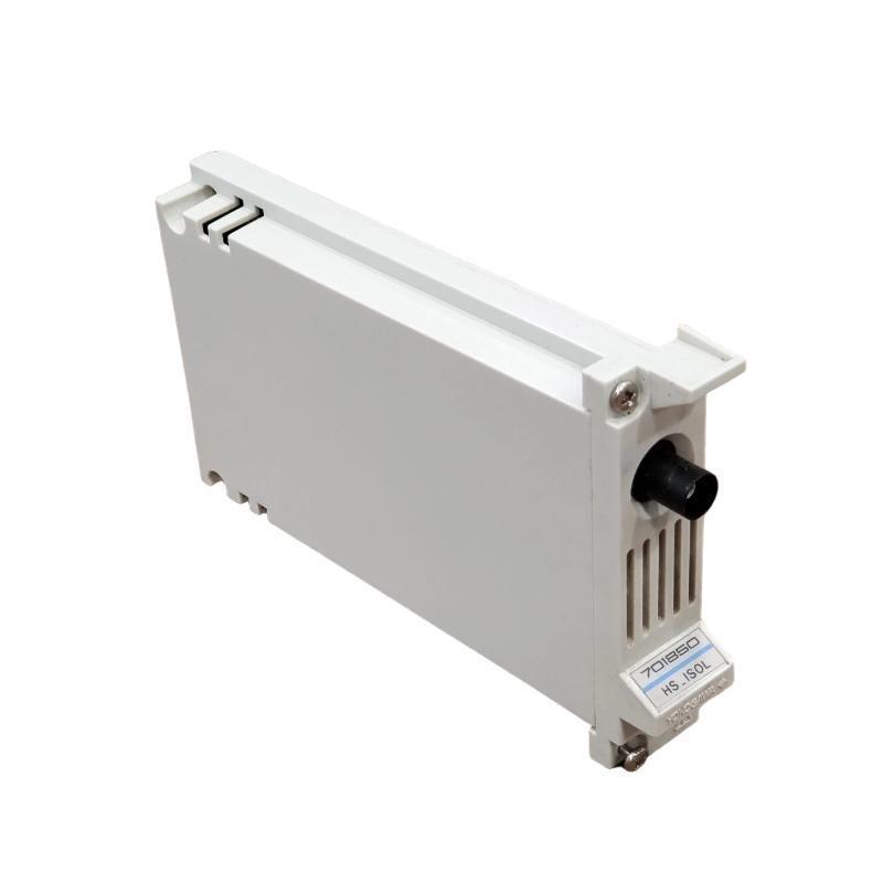
| 330180-50-00 | 3300 XL Proximitor, single channel, -24Vdc supply, 0 to -10Vdc output, panel mount, screw terminals for flying lead connection | 0.09 | 64 x 38 x 25 (L x W x H) |
| 330130-020-00-00 | 3300 XL Extension Cable, 2.0m length, fluid-resistant jacket, MS3112 connectors both ends, for use between probe and proximitor | 0.22 | Cable diameter 4.5mm; Length 2000mm |
| 330400-01-00 | 3300 XL Standard Proximitor, -24Vdc supply, DIN rail mount, screw terminals, accepts flying lead probe connections | 0.10 | 70 x 45 x 30 (L x W x H) |
| 330195-02-05-50-01-00 | 3300 XL 8mm high-temperature probe assembly, standard mount, 3/8-24 thread, 0.5m cable, flying leads, -52°C to +200°C | 0.16 | Probe body 13.5 dia x 75 length; Cable 500 |
| 3500/40M-01-00 | 4-channel Proximitor module for 3500 rack system, accepts 8mm proximity probe inputs, provides DC output and relay alarms | 0.42 | Module 241 x 38 x 220 (H x W x D) for 3500 rack |
Frequently Asked Questions (FAQ) – 10 Q&A
Q1: What is the exact weight of the 330104-04-10-05-01-00 including the cable and flying leads?
A1: The total weight of the complete probe assembly is 0.15 kg (150 grams). This weight includes the 8mm probe body with internal coil, the 0.5 meter single-shielded coaxial cable, and the 50mm stripped and tinned flying leads. The absence of a connector saves approximately 20 grams compared to connectorized versions. The weight tolerance is ±5 grams. This is the lightest 3300 XL 8mm probe available, making it ideal for mounting on thin or soft brackets.
Q2: Can I add extension cable to this flying lead probe by splicing the wires?
A2: No, you should never splice or extend the cable of a 3300 XL probe. The total cable length from probe tip to proximitor is critical to the oscillator circuit operation. If you need a longer total length, you must use a probe with a longer integral cable or use a probe with a connector and a separate extension cable. Splicing introduces impedance mismatches, changes cable capacitance, and destroys linearity. The maximum total cable length (probe cable plus any extension) is 9.0 meters. For this model, the probe cable is 0.5 meters, so you could theoretically use a 3300 XL extension cable if the probe had a connector, but it does not. Therefore, this model is only suitable when the proximitor is located within 0.5 meters of the probe.
Q3: How do I correctly wire the flying leads to a 330180-50-00 proximitor?
A3: The 330104-04-10-05-01-00 has two flying leads: white (center conductor) and black with white stripe (shield). Connect the white lead to the PROBE terminal on the proximitor. Connect the black lead to the COM terminal. Do not connect anything to the OSC terminal on the proximitor when using a probe with integral cable – the OSC terminal is for use with extension cables only. Ensure the shield (black lead) is grounded only at the proximitor end, not at the probe end. Use crimp ferrule terminals or direct screw clamping – do not solder the leads directly to the proximitor board as soldering can wick up the wire and make it brittle.
Q4: What is the maximum distance I can locate the proximitor from the probe with this model?
A4: The probe’s integral cable is exactly 0.5 meters long. The proximitor must be located such that the distance from the probe tip to the proximitor terminal block does not exceed 0.5 meters. There is no allowance for adding field wiring between the probe flying leads and the proximitor because any additional wire changes the total system capacitance. If your proximitor is more than 0.5 meters from the probe port, you must use a connectorized probe (e.g., 330104-04-10-05-01-01) with a separate extension cable. Field splicing is not permitted.
Q5: Is the 4mm unthreaded length measured from the probe tip to the start of the threads or to the end of the threads?
A5: The unthreaded length (4mm) is measured from the very tip of the probe face to the first full thread (the start of the threaded portion). It does not include the thread length. The thread length on this model is 10mm. Therefore, from the probe tip to the end of the threaded portion is 4mm (unthreaded) + 10mm (threaded) = 14mm. The overall case length of 50mm is measured from the probe tip to the point where the cable exits the probe housing. Understanding these measurements is critical when calculating how far the probe will extend through a mounting bracket.
Q6: Can this probe be used in an intrinsically safe (IS) installation?
A6: Yes, the 330104-04-10-05-01-00 can be used in intrinsically safe installations when connected through an approved IS barrier. The probe itself is a passive device (coil and cable) that stores minimal energy. The IS rating depends on the proximitor and barrier combination. For Class I, Division 1, Groups A through D installations in North America, use a 3300 XL proximitor with an approved Zener barrier or galvanic isolator. For ATEX/IECEx installations, use a certified proximitor and barrier. The flying leads must be terminated inside an approved IS junction box. Always consult the latest approval documentation for your specific configuration.
Q7: What is the correct way to measure the probe coil resistance to check for damage?
A7: To measure coil resistance, disconnect the flying leads from any proximitor or other equipment. Set your multimeter to the 200 ohm range. Measure between the white lead (center conductor) and the black lead (shield). At 25°C room temperature, a functional probe should read between 17.1 and 18.9 ohms. If the reading is below 15 ohms, there may be a short between the center conductor and shield. If the reading is above 22 ohms or infinite, there is an open circuit in the coil or cable. Also measure between each lead and the probe case (the metal body) – both readings should be infinite (open circuit). Any finite reading indicates insulation breakdown.
Q8: The cable on my 330104-04-10-05-01-00 is not armored. Is it durable enough for a refinery environment?
A8: This model uses a single-shielded, non-armored cable with a fluid-resistant jacket but no stainless steel braid. It is suitable for installation inside junction boxes, conduits, and cable trays where mechanical abrasion is minimal. For direct exposure to impact, abrasion, or rodent damage, you should select a model with armored cable (suffix indicating armored construction, such as the 330104-04-10-05-02-00 where available). In a typical refinery installation where the probe cable runs from the probe port directly into a conduit within 100mm, the non-armored cable is acceptable. If the cable runs exposed along the machine for more than 300mm, armored cable is recommended.
Q9: What does the “05” in the middle of the model number (04-10-05) represent?
A9: In the 3300 XL model numbering system, the three digits after the unthreaded length and before the case length represent the cable length in decimeters (tenths of a meter). “05” means 0.5 meters (5 decimeters). The full breakdown of 330104-04-10-05-01-00 is as follows:
-
330104 = Base probe model (8mm, standard mount, metric thread)
-
04 = Unthreaded length = 4mm
-
10 = Thread length = 10mm
-
05 = Cable length = 0.5 meters (50cm)
-
01 = Extension cable interface code (01 = flying leads with stripped ends)
-
00 = Connector or termination code (00 = no connector, flying leads)
Understanding this coding allows you to specify custom configurations from the ordering guide.
Q10: Can I cut the flying leads shorter if they are too long for my junction box?
A10: Yes, you can shorten the flying leads (the stripped portion) but do not cut the insulated cable jacket. The flying leads are factory-stripped to approximately 50mm length. If your terminal block is only 20mm wide, you can cut the tinned ends to 25mm length. However, do not cut back the outer cable jacket beyond the factory end point, as this would change the cable geometry and could affect the seal at the cable entry. Also do not remove more than 10mm of the center conductor insulation beyond what is already stripped, as the exposed shield may touch the center conductor. If you need leads shorter than 20mm, consider a different probe model with a connector or specify a custom cable length when ordering.