
NewsNEWCENTER
Featured products
Contact Us
Allen-Bradley 1756-DHRIO/C ControlLogix Data Highway Plus and Remote I/O Communication Module – Installation and Commissioning Guide
2026-11-16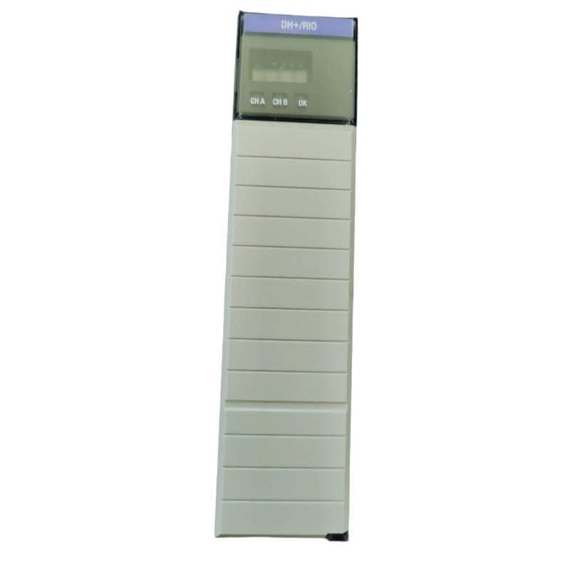
1. Introduction
The Allen-Bradley 1756-DHRIO/C is a two-channel communication interface module designed for ControlLogix automation systems. It provides connectivity to Data Highway Plus (DH+) networks and Universal Remote I/O (RIO) networks, allowing ControlLogix controllers to exchange data with legacy PLCs, remote I/O chassis, and other compatible industrial devices.
Each communication channel can be configured for its intended network function. Depending on the system architecture, the module can support DH+ messaging, Remote I/O scanning, or a combination of the two. Correct installation and configuration are essential for reliable communication between the ControlLogix chassis and existing field equipment.
2. Pre-Installation Checks
Before installing the 1756-DHRIO/C, confirm that the module is suitable for the existing ControlLogix system. Check the catalog number, Series C identification, hardware condition, and firmware compatibility. Do not assume that modules from different series or revisions can be substituted without reviewing the project configuration.
- Confirm that the ControlLogix chassis has an available compatible slot.
- Inspect the module housing, backplane connector, and network ports for physical damage.
- Verify the required DH+ or Remote I/O network topology.
- Identify the network cable type, node addresses, rack addresses, and communication rates.
- Check the controller firmware and programming software compatibility.
- Prepare the correct configuration project and any required routing information.
- Make sure the installation area meets the environmental requirements of the equipment.
For replacement work, record the existing channel assignments, switch positions, routing information, and controller configuration before removing the original module.
3. Safety and Handling Precautions
Installation should be performed by qualified industrial automation personnel. Follow the plant’s electrical safety procedures and the applicable ControlLogix chassis instructions.
- Place the controlled equipment in a safe operating condition before beginning work.
- Apply lockout/tagout procedures where required and verify the relevant energy sources are isolated.
- Protect the module from electrostatic discharge by using an approved grounding wrist strap and handling procedure.
- Avoid touching the backplane connector or exposed electronic components.
- Never force the module into the chassis. Check alignment before applying insertion pressure.
- Do not disconnect or reconnect network wiring under load unless the system design and approved procedures explicitly permit it.
4. Installing the Module in the ControlLogix Chassis
Step 1: Prepare the Chassis
Verify that the ControlLogix chassis is securely mounted and that its power supply and grounding arrangements are correct. Confirm the intended slot using the system drawings and controller project. The 1756-DHRIO/C must be installed in a compatible ControlLogix chassis.
Step 2: Inspect the Module
Check the module for damaged connectors, bent contacts, cracked housing, or signs of moisture and contamination. Confirm that the catalog number is 1756-DHRIO and that the Series C designation matches the intended replacement specification.
Step 3: Insert the Module
Align the module with the chassis guides and carefully slide it into the selected slot. Apply even pressure until the module is fully seated and secured according to the chassis installation procedure. Do not use excessive force or attempt to install the module at an angle.
Step 4: Confirm the Physical Installation
Check that the module is correctly positioned and that the front panel is accessible. Verify that the network connectors can be reached without placing excessive strain on the cables.
5. Configure the Communication Channels
The 1756-DHRIO/C provides two independent communication channels, Channel A and Channel B. Each channel must be configured according to the network to which it is connected.
DH+ Network Configuration
For DH+ applications, confirm the network type, node address, communication rate, and cable arrangement. The supported DH+ communication rates include 57.6 Kbps, 115.2 Kbps, and 230.4 Kbps, subject to the channel-specific limitations and hardware configuration. Channel A and Channel B do not necessarily support identical rate selections.
Every station on the same DH+ link must have a unique node address. Check the existing network configuration before assigning an address to avoid conflicts. Where the module is used as a message-routing interface, verify the required routing path and link identification in the communication software.
Remote I/O Configuration
When a channel is assigned to Remote I/O, the 1756-DHRIO/C operates as a Remote I/O scanner. It exchanges I/O data with compatible remote adapters and connected I/O equipment. The module is not a general-purpose Remote I/O adapter; confirm that the remote equipment is configured for the correct adapter role.
Check the logical rack number, starting group, rack size, communication rate, and block-transfer requirements. The module supports up to 32 logical rack connections or 16 block-transfer connections per Remote I/O channel, subject to the application and configuration limits.
6. Network Wiring and Connection
Connect the DH+ or Remote I/O network cables to the appropriate channel connectors. Use the specified cable type and connector arrangement for the network installation. For traditional DH+ networks, verify the data conductors, polarity, shielding, and termination arrangement against the applicable network design.
- Label Channel A and Channel B cables clearly.
- Keep network wiring away from high-voltage and high-current power cables where practical.
- Maintain the required cable routing and grounding practices.
- Check connector tightness and inspect cable insulation for damage.
- Verify network termination at the locations specified by the system design.
- Confirm that each connected device uses the intended network address.
Do not determine terminal assignments from wire color alone. Use the connector markings and the documentation for the exact module revision.
7. Controller Configuration and Software Setup
Use the appropriate Rockwell Automation programming and communication software for the installed ControlLogix controller and module revision. The configuration process depends on whether the application uses Remote I/O scanning, DH+ messaging, or both.
- Open the applicable ControlLogix project.
- Confirm the controller type, firmware revision, and chassis layout.
- If the module is being used as a Remote I/O scanner, configure it in the project as required by the system architecture.
- Set the channel operating modes and communication parameters.
- Enter the required rack, group, and block-transfer information for Remote I/O applications.
- For DH+ message routing, configure the required communication path and routing information using the appropriate communication utility.
- Review the configuration for duplicate addresses, invalid paths, and incompatible revisions.
- Save the project and follow the plant’s approved procedure for downloading or applying configuration changes.
Do not add or configure the module in the I/O tree solely because it is physically installed. The correct project configuration depends on the communication function being used. A DH+-messaging-only application and a Remote I/O scanner application may require different configuration steps.
8. Commissioning and Functional Testing
After installation and configuration, verify that the module is operating correctly before returning the controlled equipment to normal service.
Initial Power-Up
Restore chassis power according to the approved startup procedure. Observe the module’s alphanumeric status display and indicators. Allow the module to complete its startup sequence. If a fault code or abnormal status remains, record the displayed information and investigate it before proceeding.
Communication Verification
- Confirm that the module is recognized by the ControlLogix system where applicable.
- Verify that each configured channel is operating in the intended network mode.
- Check that DH+ devices can be reached through the configured communication path.
- Verify that Remote I/O adapters and racks are communicating with the scanner.
- Check input and output data updates using the approved controller monitoring tools.
- Test block transfers where they are part of the application.
- Review controller diagnostics and communication fault information.
Final Acceptance
Record the module catalog number, series, slot position, channel assignments, network rates, node or rack addresses, and relevant software configuration. Update the electrical drawings and maintenance records so future troubleshooting can be performed using the actual installed configuration.
9. Common Installation Problems
| Problem | Possible Cause | Recommended Check |
|---|---|---|
| Module does not start normally | Chassis power issue, poor seating, or module fault | Check chassis power, slot condition, and status display |
| DH+ devices cannot be reached | Incorrect node address, channel mode, cable wiring, or routing path | Verify network settings and communication routing |
| Remote I/O rack is not communicating | Incorrect scanner configuration, rack address, or network wiring | Check rack settings, adapter configuration, and cable continuity |
| Intermittent communication | Loose connections, electrical noise, or incorrect termination | Inspect cable routing, connectors, shielding, and termination |
| Configuration fault appears | Stored configuration does not match the installed chassis or project | Review module configuration and chassis identification information |
| Replacement module does not behave like the original | Different series, firmware, channel settings, or stored routing data | Compare hardware revision and recover the approved configuration |
10. Technical FAQs
Q1: What is the main function of the Allen-Bradley 1756-DHRIO/C?
It provides two-channel communication between a ControlLogix chassis and compatible DH+ or Remote I/O networks. It supports legacy network integration and communication routing in industrial control systems.
Q2: How many communication channels does the module provide?
The 1756-DHRIO/C provides two independent channels, identified as Channel A and Channel B. Each channel must be configured for its intended network function.
Q3: Can one channel be used for DH+ and the other for Remote I/O?
Yes. The channels can be assigned independently, allowing a suitable system design to use one channel for DH+ communication and the other for Remote I/O scanning.
Q4: Does the 1756-DHRIO/C operate as a Remote I/O adapter?
No. Its Remote I/O function is scanner-only. Confirm the role of the remote device before designing the network.
Q5: Which communication rates are supported?
The supported network rates include 57.6 Kbps, 115.2 Kbps, and 230.4 Kbps. Available selections depend on the network type and channel. Check the channel-specific settings before commissioning.
Q6: Does the module need to be configured in the controller I/O tree?
The required project configuration depends on the application. Remote I/O scanner operation requires the appropriate module and channel configuration. A DH+-messaging-only application may use a different setup and routing procedure.
Q7: What should be checked when replacing an existing 1756-DHRIO?
Check the series and revision, firmware compatibility, chassis slot, channel operating modes, network addresses, rack configuration, and routing information. Do not assume that stored settings will automatically transfer to the replacement module.
Q8: Why does a Remote I/O rack fail to communicate after installation?
Common causes include an incorrect channel mode, mismatched rack address, incorrect communication rate, cable wiring problems, or an incompatible remote adapter configuration.
Q9: Can the 1756-DHRIO/C be used in an existing DH+ network?
It can be integrated into a compatible DH+ network when its channel settings, node address, communication rate, wiring, and routing configuration match the existing network design.
Q10: What information should be recorded after commissioning?
Record the catalog number, series, firmware revision, chassis slot, channel assignments, network rates, node and rack addresses, routing settings, and commissioning test results.
11. Technical Summary
The Allen-Bradley 1756-DHRIO/C ControlLogix communication module provides a practical interface between modern ControlLogix controllers and established DH+ and Remote I/O networks. Correct installation requires attention to chassis compatibility, module revision, channel configuration, network wiring, addressing, and controller communication settings.
Before returning the system to service, verify both the physical installation and the communication performance of every configured channel. Maintaining accurate configuration records and following the approved procedures for the exact hardware revision will help support stable operation and simplify future maintenance.