

ProductPRODUCT
Featured products

Contact Us
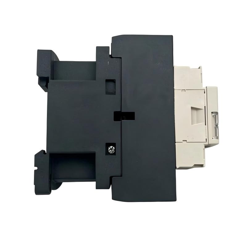
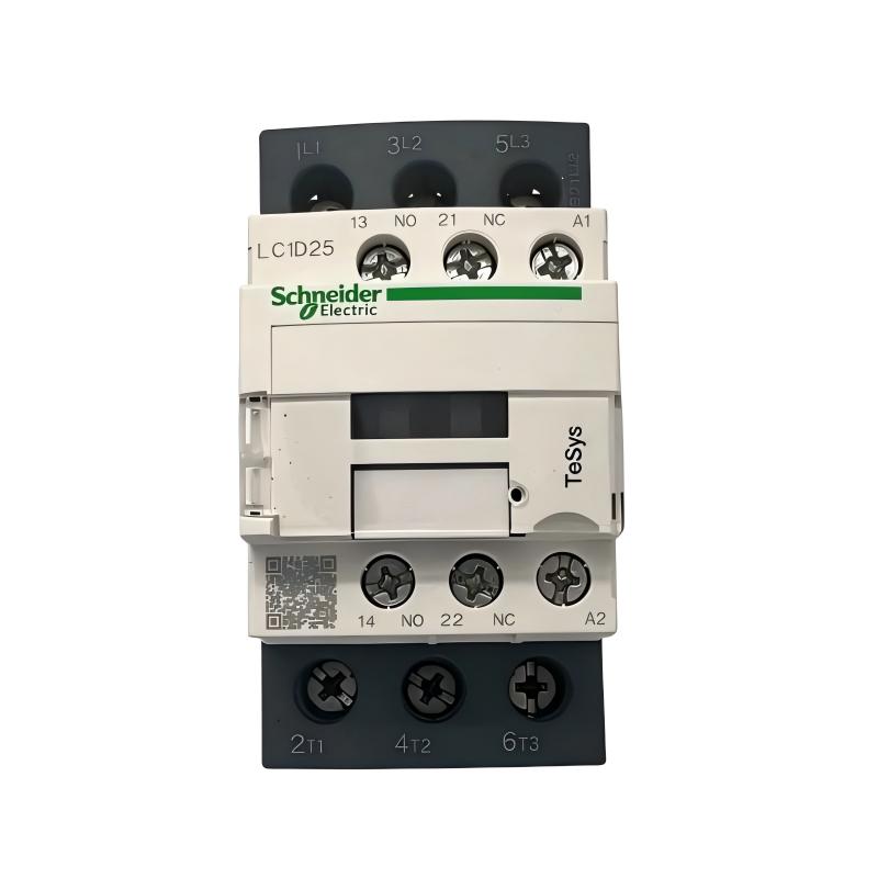
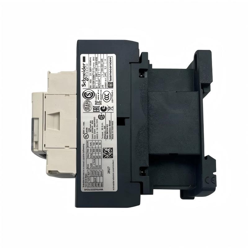
- Schneider
- LC1D25E7
- Contactor
- France
- 85 x 45 x 92 mm
- 0.37 kg
- Xiamen, China
- New & In Stock
- T/T, PayPal, Western Union
- 1 Year
- 1-3 Working Days
- DHL, UPS, TNT, FedEx and EMS.
- 24-Hour Service
- COO
- 2
Our advantage

Global Logistics
We have a 10-year logistics and express cooperation agreement, so our products can be shipped to any place in the world.

Brand new and original
Our products are imported in bulk from the place of origin. Because of the cooperative relationship, our products are all original and 100% new.

24-hour service
We provide 7*24 hours service to our customers. We will be there whenever you need us.

Price advantage
All our products are priced very favorably because we have our own warehouse and supply.
| Company Information | |||
| [email protected] | |||
| Mobile | +8615980777398 | ||
| +8615980777398 | |||
| 15980777398 |
Product Overview
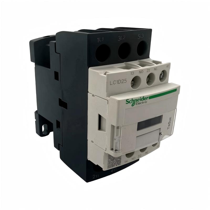
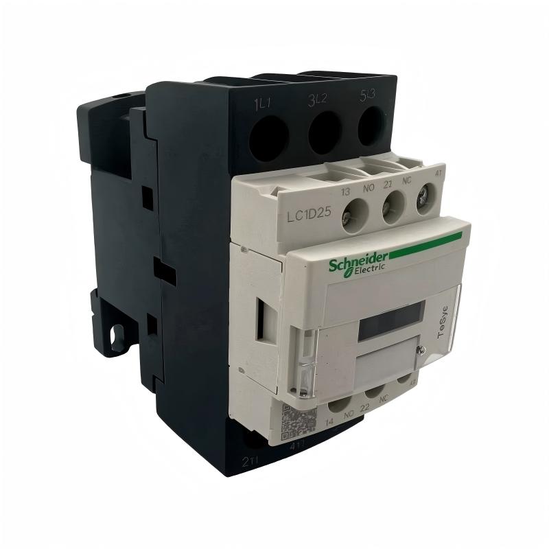
The Schneider Electric LC1D25E7 TeSys D Contactor is an industrial electromagnetic switching device designed for controlling three-phase motors and resistive electrical loads. It belongs to Schneider Electric’s TeSys D contactor family, which is widely used in motor starters, machine control panels, and industrial power distribution systems.
The LC1D25E7 features three normally open main contacts and a 48 V AC control coil operating at 50/60 Hz. When the coil receives the correct control voltage, the electromagnetic mechanism changes the state of the main contacts, allowing power to flow to the connected load. When the coil is de-energized, the contacts return to their normal open state.
This model has a rated operational current of 25 A under AC-3 conditions at up to 440 V AC and 40 A under AC-1 conditions at up to 440 V AC. Its motor-control capacity includes 11 kW at 380–400 V AC under AC-3 conditions. The contactor also includes one normally open and one normally closed auxiliary contact for control-circuit signaling and interlocking.
The LC1D25E7 is suitable for applications requiring reliable switching of motors and other electrical loads. It can be incorporated into motor starter assemblies, PLC-controlled machinery, pump systems, ventilation equipment, and industrial automation cabinets.
Its compact construction supports installation in control panels and motor-control centers. Before installation, engineers should confirm the coil voltage, load category, current rating, wiring requirements, and protective-device coordination.
Technical Specifications
| Parameter | Specification |
|---|---|
| Brand | Schneider Electric |
| Product Series | TeSys D / TeSys Deca |
| Model | LC1D25E7 |
| Product Type | AC Contactor |
| Contactor Configuration | Three-pole |
| Main Contact Configuration | 3 Normally Open (3NO) |
| Auxiliary Contacts | 1 NO + 1 NC |
| Rated Operational Current (AC-3) | 25 A at up to 440 V AC |
| Rated Operational Current (AC-1) | 40 A at up to 440 V AC |
| Control Coil Voltage | 48 V AC |
| Coil Frequency | 50/60 Hz |
| Rated Operational Voltage | Up to 690 V AC for the power circuit |
| Motor Power at 380–400 V AC | 11 kW, AC-3 |
| Motor Power at 415–440 V AC | 11 kW, AC-3 |
| Utilization Categories | AC-1, AC-3, AC-3e, AC-4 |
| Mounting | 35 mm DIN rail or panel mounting, subject to installation requirements |
| Connection Type | Screw-clamp terminals |
| Dimensions | 85 × 45 × 92 mm |
| Weight | 0.37 kg |
| Typical Application | Motor switching and industrial load control |
Function and Working Principle
The LC1D25E7 operates through electromagnetic actuation. Its coil, magnetic core, moving armature, return mechanism, and electrical contacts work together to establish or interrupt the power circuit.
1. Electromagnetic Coil Operation
The contactor uses a 48 V AC coil as its control input. When the correct voltage is applied, current flows through the coil and produces a magnetic field.
This magnetic field attracts the moving armature toward the fixed magnetic core. The resulting mechanical movement changes the state of the main and auxiliary contacts.
When the control voltage is removed, the magnetic field collapses and the return mechanism moves the armature back to its original position.
2. Main Contact Switching
The LC1D25E7 has three normally open main contacts. These contacts are designed to switch the three phases supplying a compatible motor or other load.
When the coil is energized, all three main contacts close. When the coil is de-energized, they open and interrupt the power circuit.
The contactor is suitable for AC-3 motor-control applications, where the switching duty typically involves starting a motor and interrupting current while the motor is running.
3. Auxiliary Contact Operation
The built-in auxiliary contacts consist of one normally open and one normally closed contact.
These contacts are commonly used for:
- Providing contactor status feedback.
- Maintaining a control-circuit holding function.
- Creating electrical interlocks.
- Sending operating signals to a PLC.
- Indicating whether a contactor is energized.
Auxiliary contacts support control logic but should not be confused with the main power contacts.
4. Motor Starting and Stopping
In a conventional direct-on-line motor starter, the LC1D25E7 can be used to connect a motor to its power supply. A control device energizes the coil to start the motor, while a stop command or protective-device operation interrupts the coil circuit.
The contactor itself does not provide motor overload protection. A correctly selected overload relay and suitable short-circuit protective device are required as part of the complete motor starter.
5. Electrical Load Switching
In addition to motor control, the contactor can switch compatible resistive loads. The applicable current rating depends on the utilization category, operating voltage, ambient temperature, and switching duty.
The AC-1 rating must not be substituted for the AC-3 rating when selecting a contactor for motor applications.
Role in Industrial Control Systems
The LC1D25E7 provides the power-switching function within an industrial electrical control system. It commonly operates alongside PLCs, overload relays, circuit breakers, control power supplies, push buttons, and motor protection devices.
PLC-Based Motor Control
A PLC can control the contactor coil through an appropriately rated output interface or an interposing relay. The PLC program can coordinate motor operation with sensors, process conditions, safety interlocks, and other machinery.
The auxiliary contacts can provide feedback to the PLC, allowing the controller to monitor the contactor’s commanded or auxiliary-contact state.
Motor Starter Assemblies
The LC1D25E7 can be incorporated into a motor starter with an overload relay and short-circuit protective device. This arrangement provides the switching and protection functions needed for a conventional motor-control circuit.
The selected overload relay must match the motor’s rated current and operating conditions.
Control Panel Integration
The contactor’s compact form supports installation in industrial electrical cabinets. It can be arranged alongside terminal blocks, circuit protection, PLC I/O modules, relays, and other control equipment.
Adequate wiring space, heat management, electrical clearance, and accessibility should be considered during panel design.
Interlocking and Status Feedback
The auxiliary contacts can support electrical interlocking between contactors or provide feedback to a machine-control system. This is useful in forward/reverse motor circuits and other applications where mutually exclusive switching states are required.
The control logic and wiring should be designed to prevent unintended simultaneous operation.
Industrial Applications
1. Pumping Systems
The LC1D25E7 can be used in pump motor starter circuits where the motor rating and switching duty are within the contactor’s specifications.
Typical applications include industrial water circulation, auxiliary process pumps, and general fluid-transfer equipment.
2. Fan and Ventilation Equipment
Industrial fans and ventilation systems use contactors to switch motor power in response to operating commands. The LC1D25E7 can be incorporated into suitable fan starter circuits.
Overload protection and appropriate short-circuit protection should be provided separately.
3. Conveyor Systems
Conveyor motors often require reliable start and stop switching. The contactor can be integrated into a motor starter controlled by push buttons, PLC outputs, or an automated production sequence.
For applications with frequent starts or high switching cycles, the electrical life and utilization category must be evaluated.
4. Packaging Machinery
Packaging machines may contain several motors for feeding, conveying, sealing, and auxiliary operations. Contactors can provide the power-switching interface between the control circuit and individual motor loads.
The LC1D25E7 can be used where its coil voltage and contact ratings match the machine design.
5. Industrial Manufacturing Equipment
Manufacturing systems use contactors to control pumps, fans, machine tools, and other electrical equipment. The LC1D25E7 can serve as part of a larger motor-control and power-distribution arrangement.
6. HVAC and Building Services
Compatible HVAC equipment may use contactors to switch motors and resistive loads. The correct utilization category and load current must be confirmed before selecting the contactor.
Installation and System Integration
Correct installation is essential for reliable switching performance and electrical safety.
1. Verify the Coil Voltage
The LC1D25E7 uses a 48 V AC coil operating at 50/60 Hz. Confirm that the control power supply provides the correct voltage before connecting the coil terminals.
A contactor with the same current rating but a different coil voltage is not necessarily interchangeable.
2. Check the Load Rating
Confirm the motor’s rated current, operating voltage, power, and starting characteristics. For motor applications, use the AC-3 rating rather than the higher AC-1 rating.
The contactor must be selected according to the actual load and operating conditions.
3. Mounting and Panel Layout
The contactor supports DIN rail or panel mounting according to the applicable installation arrangement. The supplied dimensions are 85 × 45 × 92 mm.
Provide sufficient space for terminal wiring, accessory installation, heat dissipation, and maintenance access. Verify clearances against the manufacturer’s installation instructions.
4. Power and Control Wiring
Connect the main power circuit and coil-control circuit according to the wiring diagram. Use conductors with suitable cross-sections and tightening torque.
Keep control wiring organized and separated from power wiring where necessary. Ensure that all electrical connections are secure before energizing the equipment.
5. Overload and Short-Circuit Protection
The LC1D25E7 is a switching device, not a complete motor protection system.
A suitable overload relay should be selected according to the motor’s rated current. Upstream short-circuit protection must also be coordinated with the contactor and the applicable electrical standards.
6. Functional Testing
After installation, verify the coil voltage, terminal connections, and mechanical mounting. Test the contactor using the intended control circuit and confirm that the main and auxiliary contacts operate correctly.
Check for abnormal noise, overheating, contact damage, or loose wiring during commissioning and subsequent maintenance.
Compatible System Components
The LC1D25E7 is commonly used with other electrical control and protection devices.
| Component | Function | Integration Considerations |
|---|---|---|
| PLC | Controls motor start and stop sequences | Use a correctly rated output interface for the 48 V AC coil circuit |
| Overload Relay | Protects the motor against sustained overload | Match the relay’s adjustment range to the motor nameplate current |
| Circuit Breaker | Provides upstream short-circuit protection | Coordinate its rating and characteristics with the motor starter |
| 48 V AC Control Supply | Energizes the contactor coil | Verify voltage, frequency, and available control power |
| Auxiliary Relay | Provides additional control logic | Confirm coil and contact ratings |
| Push Buttons | Provides local start and stop commands | Integrate with the control circuit and required interlocks |
| HMI | Provides operator commands and system status | Typically communicates through the PLC |
| Terminal Blocks | Organizes power and control wiring | Select suitable terminal ratings and conductor sizes |
| Three-Phase Motor | Converts electrical power into mechanical motion | Verify motor current, power, voltage, and duty |
Alternative Models and Replacement Considerations
When replacing the LC1D25E7, the most important factors are the coil voltage, main contact arrangement, current rating, and application category.
| Model or Product Option | Main Difference | Selection Consideration |
|---|---|---|
| Schneider LC1D25E7 | 25 A, three-pole, 48 V AC coil | Original reference model |
| Schneider LC1D25M7 | 25 A, three-pole, 220 V AC coil | Different coil voltage; not a direct coil replacement |
| Schneider LC1D25B7 | 25 A, three-pole, 24 V AC coil | Requires a compatible 24 V AC control supply |
| Schneider LC1D25G7 | 25 A, three-pole, 120 V AC coil | Verify control-circuit voltage |
| Schneider LC1D25P7 | 25 A, three-pole, 230 V AC coil | Different coil voltage and control wiring requirements |
| Schneider LC1DT25E7 | Four-pole contactor configuration | Different main contact arrangement |
A replacement should be checked for:
- Main contact configuration.
- AC-3 and AC-1 current ratings.
- Coil voltage and frequency.
- Auxiliary contact arrangement.
- Mounting dimensions.
- Terminal layout and wiring requirements.
- Required accessories and electrical clearances.
A similar model number does not guarantee identical electrical characteristics.
Key Advantages
Reliable Electromagnetic Switching
The electromagnetic operating mechanism provides controlled switching of compatible motor and resistive loads.
Three-Pole Main Contacts
The three normally open main contacts support switching of three-phase power circuits.
48 V AC Control Coil
The 48 V AC coil allows integration with compatible industrial control power systems.
Auxiliary Contact Feedback
The built-in 1NO + 1NC auxiliary contacts support status indication, interlocking, and control-circuit functions.
Flexible Motor-Control Applications
The contactor supports AC-3 motor-control duties and AC-1 resistive-load applications within its specified ratings.
Compact Installation
Its compact dimensions allow installation in many industrial control cabinets and motor starter assemblies.
Industrial System Compatibility
The TeSys D contactor family can be integrated into conventional motor-control circuits with suitable overload relays, circuit breakers, PLCs, and control devices.
Technical FAQs
1. What is the Schneider Electric LC1D25E7?
The LC1D25E7 is a three-pole TeSys D contactor designed for motor control and resistive-load switching. It has a 25 A AC-3 rating and a 48 V AC control coil.
2. What is the coil voltage of the LC1D25E7?
The control coil operates at 48 V AC and supports both 50 Hz and 60 Hz supply frequencies.
3. How many main contacts does this contactor have?
It has three normally open main contacts, commonly described as 3P (3NO).
4. Does the LC1D25E7 have auxiliary contacts?
Yes. It includes one normally open and one normally closed auxiliary contact, or 1NO + 1NC.
5. What is its rated current?
The rated operational current is 25 A under AC-3 conditions at up to 440 V AC. Under AC-1 conditions, the rating is 40 A at up to 440 V AC.
6. What motor power can it control?
Its published AC-3 motor rating is 11 kW at 380–400 V AC. The appropriate selection must still be based on the motor’s current, operating conditions, and applicable standards.
7. Can the LC1D25E7 be controlled by a PLC?
Yes. A PLC can control the contactor through a suitable output interface or interposing relay. The interface must be compatible with the contactor’s 48 V AC coil.
8. Does this contactor provide motor overload protection?
No. It performs the switching function. A correctly selected overload relay and suitable upstream short-circuit protection are required for a complete motor starter.
9. How is the LC1D25E7 mounted?
It can be installed on a suitable 35 mm DIN rail or mounted on a panel according to the manufacturer’s instructions and the selected assembly arrangement.
10. What should be checked before replacing this contactor?
Verify the exact model, coil voltage, main contact configuration, current rating, auxiliary contacts, mounting arrangement, and utilization category. These factors determine whether another contactor is a suitable replacement.
Procurement and Maintenance Recommendations
When purchasing the Schneider Electric LC1D25E7, verify the complete model number and inspect the product label. Pay particular attention to the 48 V AC coil specification, three-pole main contact configuration, and auxiliary contact arrangement.
For replacement projects, compare the existing contactor’s electrical ratings with the motor nameplate and the control-circuit design. Do not substitute a contactor with a different coil voltage simply because its main current rating is the same.
During routine maintenance, inspect the contactor for signs of overheating, discoloration, loose terminals, mechanical damage, or abnormal operating noise. Check the condition of the main and auxiliary contacts and verify that the mounting and wiring remain secure.
Contactors are electromechanical devices with finite electrical and mechanical operating lives. Applications involving frequent switching, heavy starting currents, or demanding operating cycles may require more frequent inspection and replacement planning.
Keep the control cabinet clean and maintain suitable operating conditions. Always isolate the electrical supply and follow appropriate safety procedures before inspecting or servicing the contactor.
Conclusion
The Schneider Electric LC1D25E7 TeSys D Contactor is a three-pole electromagnetic switching device with a 25 A AC-3 rating, a 40 A AC-1 rating, and a 48 V AC control coil. Its 3NO main contacts and 1NO + 1NC auxiliary contacts make it suitable for a range of industrial motor-control and electrical switching applications.
With dimensions of 85 × 45 × 92 mm and a weight of 0.37 kg, the LC1D25E7 is a compact component for motor starter assemblies and industrial control panels. Correct coil-voltage selection, load-rating verification, and coordination with overload and short-circuit protection are essential for reliable operation.