

ProductPRODUCT
Featured products
Contact Us
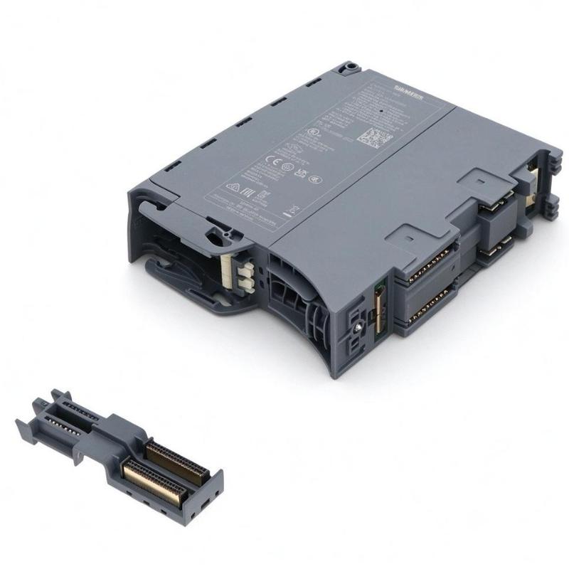
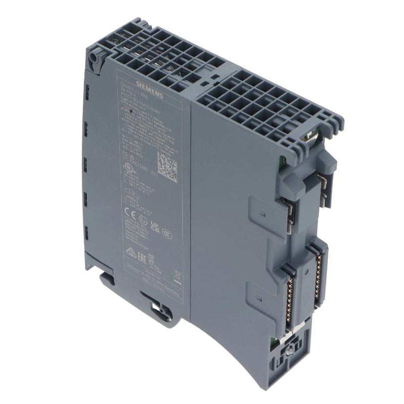
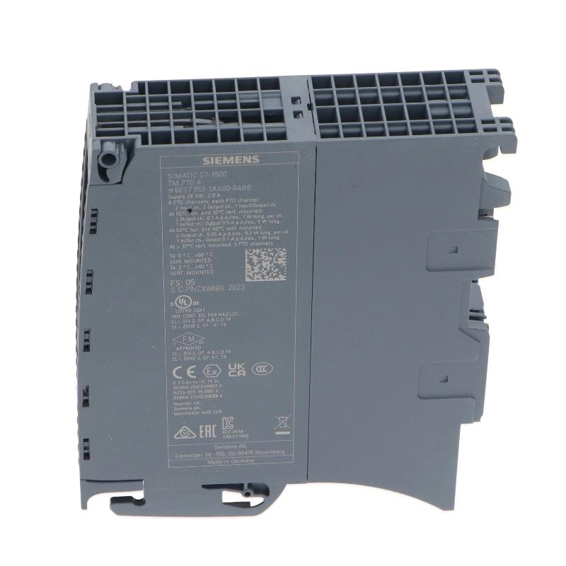
- Siemens
- 6ES7553-1AA00-0AB0
- Pulse Train Output Module
- Germany
- 35 × 147 × 129 mm
- 0.411 kg
- Xiamen, China
- New & In Stock
- T/T, PayPal, Western Union
- 1 Year
- 1-3 Working Days
- DHL, UPS, TNT, FedEx and EMS.
- 24-Hour Service
- COO
- 10
Our advantage

Global Logistics
We have a 10-year logistics and express cooperation agreement, so our products can be shipped to any place in the world.

Brand new and original
Our products are imported in bulk from the place of origin. Because of the cooperative relationship, our products are all original and 100% new.

24-hour service
We provide 7*24 hours service to our customers. We will be there whenever you need us.

Price advantage
All our products are priced very favorably because we have our own warehouse and supply.
| Company Information | |||
| [email protected] | |||
| Mobile | +8615980777398 | ||
| +8615980777398 | |||
| 15980777398 |
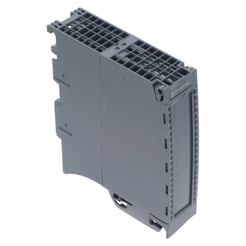
Product Overview
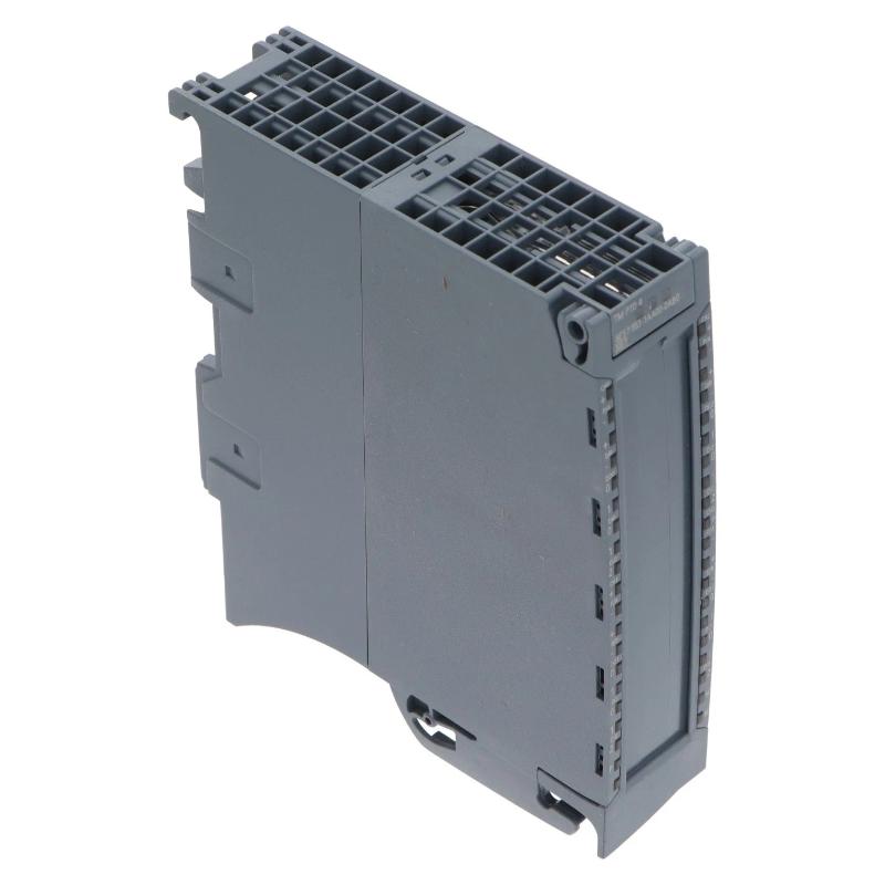
The Siemens 6ES7553-1AA00-0AB0 SIMATIC S7-1500 Pulse Train Output Module, identified as TM PTO 4, is a four-channel technology module for controlling stepper drive axes through pulse train output (PTO) signals. It provides the interface between the SIMATIC S7-1500 controller and compatible stepper drive systems, allowing the PLC to command motor speed, direction, and positioning through precisely generated pulse sequences.
Unlike standard digital output modules that simply switch electrical signals on or off, the TM PTO 4 generates pulse sequences according to motion commands from the PLC. Each pulse represents a defined movement increment, while the pulse frequency determines the commanded movement speed. This makes the module suitable for positioning applications where a stepper drive must follow a defined movement profile.
A typical application is an automated packaging machine with several independently controlled positioning axes. One stepper motor may control the film feeding mechanism, another may adjust the sealing position, and additional motors may operate product guides or indexing mechanisms. The 6ES7553-1AA00-0AB0 provides four separate PTO channels, allowing these axes to receive their motion commands through one technology module.
The module supports three pulse signal interfaces: 24 V asymmetrical, RS422 symmetrical, and 5 V TTL asymmetrical. This gives machine builders different electrical connection options depending on the stepper drive interface. The RS422 interface supports pulse frequencies up to 1 MHz, while the 24 V and 5 V TTL interfaces support up to 200 kHz.
Each channel can be configured for different PTO signal types, including pulse and direction, count up/count down, and phase-shifted incremental encoder signals. This allows the output configuration to match the control requirements of the connected drive or receiving device.
Another important feature is its integration with S7-1500 Motion Control technology objects. The module supports speed-controlled axes, positioning axes, and synchronous axes. Motion commands generated by the PLC are transferred through the module’s control interface, while feedback information such as operating status and actual speed is returned to the controller.
Each channel also includes digital inputs and outputs for drive-related signals. These can be assigned to functions such as drive enable, reference switch, measuring input, and drive-ready feedback. As a result, the module handles more than pulse generation alone; it also provides signal connections needed for coordinating the drive with the machine control sequence.
For example, in a rotary indexing machine, the PLC can command a stepper drive to move a positioning table through a specified number of pulses. A reference switch establishes the machine’s reference position, while the drive-ready signal confirms that the drive is available for operation. The TM PTO 4 handles the pulse output, and the CPU coordinates the movement with other machine operations.
The 6ES7553-1AA00-0AB0 is particularly suitable for S7-1500 applications involving multiple stepper axes, repeatable positioning, and pulse-based drive control.
Technical Specifications
| Parameter | Specification |
|---|---|
| Manufacturer | Siemens |
| Model | 6ES7553-1AA00-0AB0 |
| Product Type | TM PTO 4 Pulse Train Output Module |
| Product Family | SIMATIC S7-1500 |
| Module Category | Technology Module |
| Number of Channels | 4 Axes |
| Main Function | Pulse Train Output for Stepper Drives |
| PTO Signal Interfaces | 24 V Asymmetrical, RS422 Symmetrical, TTL (5 V) Asymmetrical |
| PTO Signal Types | Pulse and Direction, Count Up/Down, Incremental Encoder A/B |
| Maximum Pulse Frequency | 200 kHz at 24 V; 1 MHz at RS422; 200 kHz at 5 V TTL |
| Digital Inputs | 12; 3 per channel, including 1 DIQ |
| Digital Outputs | 12; 3 per channel, including 1 DIQ |
| Digital Input Functions | Synchronization, Probe, Drive Ready |
| Digital Output Functions | PTO Signal Generation, Drive-Related Control |
| Rated Supply Voltage | 24 V DC |
| Permissible Supply Voltage Range | 19.2–28.8 V DC |
| Maximum Current Consumption | 70 mA without load |
| Backplane Bus Power Consumption | 1.3 W |
| Typical Power Loss | 4 W |
| Input Address Space | 18 Bytes per Channel |
| Output Address Space | 10 Bytes per Channel |
| Supported Technology Objects | Speed-Controlled Axis, Positioning Axis, Synchronous Axis, Probe |
| Isochronous Mode | Supported |
| Minimum Bus Cycle Time | 250 µs; 375 µs when all 4 channels are used |
| Maximum Jitter | 1 µs |
| Output Short-Circuit Protection | Electronic / Thermal |
| Output Switching Delay | Typically 1 µs for DQn.0 and DQn.1 with resistive load |
| Configuration Software | STEP 7 V14 or Later / TIA Portal |
| Alternative Configuration | STEP 7 V5.5 SP3 with GSD File |
| Mounting Type | S7-1500 Mounting Rail |
| Dimensions | 35 × 147 × 129 mm |
| Weight | 0.411 kg |
Product Features
- Four Independent PTO Channels: Controls up to four stepper drive axes through one S7-1500 technology module.
- Multiple Signal Interfaces: Supports 24 V asymmetrical, RS422 differential, and 5 V TTL pulse connections.
- High-Frequency Pulse Generation: Supports output frequencies up to 1 MHz through the RS422 interface.
- Pulse and Direction Mode: Generates movement pulses together with a direction signal for compatible stepper drives.
- Count Up/Down Mode: Supports separate pulse signals for forward and reverse movement.
- Incremental Signal Output: Supports phase-shifted A/B signals with simple or quadruple evaluation.
- Motion Control Integration: Works with speed-controlled, positioning, and synchronous axis technology objects.
- Drive Feedback Inputs: Provides configurable inputs for drive-ready, reference switch, and measuring functions.
- Synchronization Functions: Supports external synchronization signals for coordinated positioning operations.
- Probe Function: Allows external measuring events to be incorporated into motion-related applications.
- Isochronous Operation: Synchronizes pulse output processing with the S7-1500 system cycle.
- Electrical Protection: Includes electronic and thermal short-circuit protection for digital outputs.
Working Principle
The 6ES7553-1AA00-0AB0 generates pulse trains according to motion commands received from the S7-1500 CPU. These pulses are transmitted to the connected stepper drive, which uses them to determine how far and how quickly its motor should move.
The basic control arrangement is:
S7-1500 CPU → Motion Control Technology Object → TM PTO 4 → Pulse Train Signals → Stepper Drive → Stepper Motor
The process begins when the PLC program issues a motion command through a configured technology object. The command contains the required movement information, such as the target position or speed. The TM PTO 4 converts the motion command into the corresponding pulse output signals.
Pulse and Direction Control
In pulse and direction mode, one output generates the movement pulses while another signal indicates the direction of rotation. The connected stepper drive interprets the pulse frequency as the commanded speed and the total pulse count as the requested movement.
For example, in a labeling machine, a stepper motor may control the movement of a label feeding roller. The PLC calculates the required feeding distance and sends the corresponding positioning command. The TM PTO 4 generates the pulse sequence, while the direction signal determines whether the roller moves forward or backward.
Count Up and Count Down
The module also supports separate pulse signals for count-up and count-down operation. In this configuration, the receiving equipment interprets the signals as movement commands in opposite directions.
This mode can be useful in positioning systems where forward and reverse movement signals are handled separately by the connected drive.
Incremental Encoder Signal Output
The TM PTO 4 supports phase-shifted A/B signal output, including simple and quadruple evaluation arrangements. This allows the module to generate incremental signal patterns for compatible receiving equipment.
The signal configuration must match the requirements of the connected device. It should not be confused with the conventional pulse-and-direction interface used by many stepper drives.
Motion Control and Positioning
The module works with S7-1500 Motion Control technology objects. A speed-controlled axis can receive velocity commands, while a positioning axis executes movements toward specified target positions. Synchronous axis applications allow movement to be coordinated with another axis or machine reference.
During operation, the technology object exchanges control and feedback information with the module. The CPU can monitor operating status, drive readiness, and actual speed information while coordinating the machine sequence.
Reference and Measuring Signals
Each channel includes configurable digital input functions. A reference switch can establish a known machine position during homing, while the probe function can capture a measurement event during movement.
For example, a positioning table may move until its reference sensor is activated. The reference signal is processed through the corresponding input, allowing the controller to establish a machine reference before executing normal positioning commands.
The drive-ready input can also be used to prevent movement commands from being issued before the drive is prepared for operation.
Isochronous Operation
In isochronous mode, the module synchronizes its pulse output processing with the configured S7-1500 system cycle. This is useful in applications where several axes must follow coordinated movement sequences.
The combination of four PTO channels, multiple electrical interfaces, and Motion Control integration allows the TM PTO 4 to handle multi-axis stepper drive applications without requiring a separate pulse generator for every axis.
Role in the SIMATIC S7-1500 Control Architecture
The 6ES7553-1AA00-0AB0 serves as the pulse-generation interface between the S7-1500 controller and external stepper drives. It receives motion commands from the CPU and converts them into electrical pulse signals suitable for the selected drive interface.
A typical system arrangement follows this structure:
SIMATIC S7-1500 CPU → Motion Control Technology Objects → TM PTO 4 → Stepper Drives → Motors
| System Component | Function |
|---|---|
| Siemens 6ES7553-1AA00-0AB0 | Generates pulse train signals for four independent axes |
| SIMATIC S7-1500 CPU | Executes machine logic and generates motion commands |
| S7-1500 Mounting Rail | Provides mechanical mounting for the technology module |
| Front Connector | Provides electrical connections for pulse signals and digital I/O |
| Stepper Drive | Converts pulse commands into motor movement |
| Stepper Motor | Executes the commanded rotational or positioning movement |
| Reference Switch | Provides a machine reference signal for homing |
| Drive-Ready Signal | Indicates whether the connected drive is ready for operation |
| Measuring Sensor | Supplies external measurement or probe signals |
| 24 V DC Power Supply | Supplies the module and connected digital equipment |
| STEP 7 / TIA Portal | Configures the PTO channels and Motion Control technology objects |
| S7-1500 Motion Control | Manages positioning, speed control, and synchronized axis movements |
Within this architecture, the CPU handles the overall machine sequence and movement calculations, while the TM PTO 4 manages the electrical pulse output.
For a four-axis packaging machine, the controller can coordinate separate stepper motors for feeding, positioning, sealing, and indexing. Each axis has its own PTO channel, allowing the machine to execute different movement commands through one module.
The digital input and output signals also provide the necessary drive-related feedback and control connections. This allows the controller to consider drive readiness and reference information when executing motion sequences.
Industrial Applications
| Application | Typical Use |
|---|---|
| Packaging Machinery | Controlling film feeding, product positioning, and indexing mechanisms |
| Labeling Machines | Driving label feeding rollers and positioning systems |
| Automated Assembly | Controlling stepper-driven positioning and component feeding axes |
| Rotary Indexing Tables | Generating pulse commands for repeatable angular positioning |
| CNC Auxiliary Axes | Controlling compatible stepper-driven positioning mechanisms |
| Material Feeding Equipment | Regulating feed length and movement speed through pulse commands |
| Printing Machinery | Controlling paper feeding and positioning mechanisms |
| Pick-and-Place Equipment | Operating stepper-driven positioning axes |
| Automated Dispensing Systems | Controlling movement of dispensing heads and feed mechanisms |
| Textile Machinery | Coordinating multiple stepper-driven rollers and positioning units |
Installation and Maintenance
- Verify the Module Type: Confirm that Siemens 6ES7553-1AA00-0AB0 is the required TM PTO 4 module and that four pulse-output channels meet the machine’s requirements.
- Check CPU Compatibility: Verify that the S7-1500 CPU and engineering software support the intended Motion Control technology objects.
- Inspect the Module: Examine the housing, mounting contacts, and front connector interface for physical damage or contamination.
- Prepare the Mounting Rail: Ensure that the S7-1500 mounting rail is correctly installed and that the designated module position is available.
- Isolate the Power Supply: Disconnect the relevant power sources and follow electrical safety procedures before installing or removing the technology module.
- Install the Module: Mount the TM PTO 4 in the designated S7-1500 configuration and verify that it is correctly seated.
- Select the PTO Interface: Identify whether each connected drive requires 24 V asymmetrical, RS422 symmetrical, or 5 V TTL asymmetrical signals.
- Connect the Drive Signals: Wire the pulse, direction, and other required signals according to the selected PTO operating mode and channel assignment.
- Connect Digital Feedback Signals: Wire the drive-ready, reference switch, and measuring inputs according to the configured application.
- Configure the Technology Objects: Use STEP 7 or TIA Portal to assign the axes and configure speed, positioning, pulse interface, and synchronization parameters.
- Test Axis Operation: Verify pulse output, motor direction, reference detection, drive-ready feedback, and positioning behavior under controlled operating conditions.
- Document the Configuration: Record channel assignments, drive interfaces, pulse frequencies, motor settings, reference positions, and Motion Control parameters for future maintenance.
Compatible System Components
| Component | Function |
|---|---|
| Siemens 6ES7553-1AA00-0AB0 | TM PTO 4 pulse train output module |
| SIMATIC S7-1500 CPU | Executes machine logic and generates motion commands |
| S7-1500 Mounting Rail | Provides mechanical installation support |
| S7-1500 Front Connector | Provides electrical connections for PTO and digital signals |
| Stepper Drive | Receives pulse and direction commands |
| Stepper Motor | Executes the movement commanded by the drive |
| 24 V DC Power Supply | Supplies the module and connected digital equipment |
| RS422-Compatible Drive | Receives differential pulse signals |
| 5 V TTL-Compatible Drive | Receives asymmetrical TTL pulse signals |
| Reference Switch | Establishes a reference position during homing |
| Measuring Sensor | Provides external measuring and probe signals |
| Drive-Ready Output | Supplies operating readiness feedback to the module |
| STEP 7 / TIA Portal | Configures the PTO module and Motion Control functions |
| SIMATIC S7-1500 Motion Control | Manages speed-controlled, positioning, and synchronous axes |
Recommended Related Models
| Model | Product Type | Typical Application |
|---|---|---|
| Siemens 6ES7550-1AA01-0AB0 | SIMATIC S7-1500 TM Count 2x24V Counter Module | High-speed pulse counting and encoder evaluation |
| Siemens 6ES7551-1AB00-0AB0 | SIMATIC S7-1500 TM PosInput 2 Position Detection Module | Incremental and absolute encoder position acquisition |
| Siemens 6ES7552-1AA00-0AB0 | SIMATIC S7-1500 TM Timer DIDQ 16x24V Technology Module | Time-based digital signal processing |
| Siemens 6ES7521-1BH00-0AB0 | SIMATIC S7-1500 Digital Input Module | Acquiring drive feedback and machine sensor signals |
| Siemens 6ES7522-1BL01-0AB0 | SIMATIC S7-1500 Digital Output Module | Controlling external digital actuators |
| Siemens 6ES7541-1AB00-0AB0 | SIMATIC S7-1500 CM PtP RS422/485 HF Communication Module | Serial communication with compatible automation equipment |
Key Advantages
- Controls up to four stepper drive axes through one technology module.
- Supports 24 V, RS422, and 5 V TTL pulse interfaces.
- Generates pulse frequencies up to 1 MHz through RS422.
- Supports pulse and direction, count up/down, and incremental A/B signal formats.
- Integrates with S7-1500 speed-controlled and positioning technology objects.
- Provides configurable drive-ready, reference, and measuring inputs.
- Supports synchronized axis operation through isochronous mode.
- Includes electronic and thermal short-circuit protection for digital outputs.
Technical FAQs
How many stepper drive axes can the Siemens 6ES7553-1AA00-0AB0 control?
The TM PTO 4 supports four independent axes. Each channel generates its own pulse train output and includes associated digital signal connections. This allows one module to handle up to four compatible stepper drive interfaces within an S7-1500 automation system.
What is the maximum pulse output frequency of the TM PTO 4?
The maximum frequency depends on the selected electrical interface. The 24 V asymmetrical interface supports up to 200 kHz, the RS422 symmetrical interface supports up to 1 MHz, and the 5 V TTL asymmetrical interface supports up to 200 kHz. The connected drive must support the selected signal type and frequency.
Which motion control functions are supported by the 6ES7553-1AA00-0AB0?
The module supports speed-controlled axes, positioning axes, and synchronous axes through compatible S7-1500 Motion Control technology objects. It also supports probe functions for measuring events during movement. The specific functions available depend on the CPU, technology object, and engineering configuration.
Can the module work with both pulse-and-direction and incremental A/B signals?
Yes. The TM PTO 4 supports pulse and direction, separate count-up/count-down signals, and phase-shifted incremental A/B signal formats. The required signal type must be selected according to the connected drive or receiving equipment. The electrical interface must also be configured to match the device’s input requirements.