
NewsNEWCENTER
Featured products
Contact Us
Emerson A6110 Shaft Relative Vibration Monitor Installation and Commissioning Guide
2026-11-04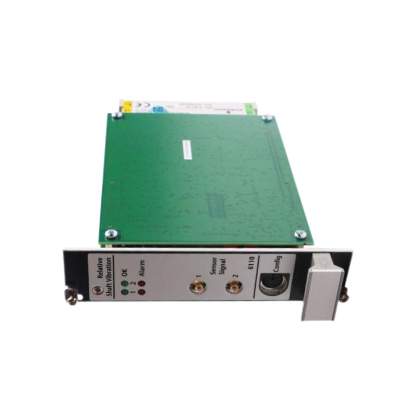
1. Product Overview
The **Emerson A6110 Shaft Relative Vibration Monitor** is a dual-channel machinery protection module designed for the Emerson AMS 6500 Machinery Health Monitor system. It is used to monitor shaft relative vibration in critical rotating machinery and provide measurement and protection functions for industrial equipment. The A6110 is designed for applications involving steam turbines, gas turbines, compressors, and hydro turbines. It measures shaft movement relative to the bearing housing using non-contact eddy-current displacement sensors. The measured vibration signals are evaluated against configured alarm thresholds, allowing the machinery protection system to generate alert and danger conditions. The module occupies one slot in the AMS 6500 rack and uses a compact 3U format. Its two measurement channels can operate independently or in combined monitoring modes, making it suitable for different rotating machinery monitoring arrangements. The A6110 also provides buffered measurement outputs, proportional outputs, alarm functions, and built-in self-checking capabilities. It can be integrated with other AMS 6500 monitoring modules to form a machinery protection system designed around API 670 requirements.
2. Technical Specifications
| Parameter | Specification |
|---|---|
| Manufacturer | Emerson |
| Model | A6110 |
| Product Type | Shaft Relative Vibration Monitor |
| System | AMS 6500 Machinery Health Monitor |
| Number of Inputs | Two channels |
| Monitoring Modes | Independent or combined |
| Input Type | Eddy current, differential |
| Supported Sensors | PR6422, PR6423, PR6424, PR6425 |
| Supported Drivers | CON 011/91, CON 021/91, CON 041/91 |
| Input Resistance | Greater than 100 kΩ |
| Input Voltage Range | 0 to -22 VDC |
| Input Frequency Range | Lower cutoff: 1 or 5 Hz; upper cutoff: 50–2000 Hz, adjustable |
| Measurement Range | 0–400 mV to 0–8000 mV, configurable |
| Sensor Supply | -26.7 V nominal |
| Sensor Supply Current | 20 mA nominal, 35 mA maximum |
| Power Consumption | Maximum 6 W |
| Supply Current | 250 mA maximum at 24 VDC |
| Operating Temperature | 0°C to 65°C |
| Storage Temperature | -30°C to 85°C |
| Relative Humidity | 5–95%, non-condensing |
| Dimensions | 30.0 × 128.4 × 160.0 mm |
| Net Weight | Approximately 0.32 kg |
| Rack Space | One slot, 3U format |
Specifications should be checked against the exact A6110 hardware revision and AMS 6500 system configuration before installation.
3. Main Functions and Working Principles
3.1 Shaft Relative Vibration Measurement
The A6110 measures the vibration of a rotating shaft relative to its bearing housing. A non-contact eddy-current displacement sensor is installed near the shaft surface, where it detects changes in the distance between the sensor tip and the rotating shaft. As the shaft moves during operation, the sensor produces an electrical signal representing shaft displacement. The A6110 processes this signal to provide vibration information for machinery condition monitoring. Shaft relative vibration is particularly important for machines with sleeve bearings, where the rotor and bearing housing have different vibration characteristics.
3.2 Dual-Channel Monitoring
The A6110 has two independent measurement inputs. These can be configured for separate measurement tasks or combined monitoring modes according to the application. For example, two sensors may be installed at different angular positions around a bearing to monitor shaft movement in different directions. This arrangement allows maintenance personnel to evaluate shaft behavior more comprehensively and identify abnormal vibration conditions.
3.3 Alarm and Protection Functions
The monitor compares measured vibration parameters with configured alarm setpoints. The system supports different alarm levels, including: – Alert: indicates that the monitored vibration has reached a warning threshold. – Danger: indicates that the vibration has reached a higher protection threshold. – OK: indicates that the monitor’s self-checking functions report normal operating conditions. Alarm thresholds, hysteresis, and time delays should be configured according to the machine manufacturer’s recommendations and the plant’s machinery protection philosophy.
3.4 Sensor and Cable Self-Checking
The A6110 includes self-checking functions for monitoring hardware, power input, internal temperature, sensor condition, and cable condition. These functions help identify abnormal monitoring conditions that could affect measurement reliability.
3.5 Signal Outputs
The module provides front and rear buffered outputs and proportional outputs for integration with other monitoring and control equipment. Depending on the configured output function, available signal formats include: – Buffered sensor signal outputs. – 0/4–20 mA proportional outputs. – 0–10 V proportional outputs. These signals can support external monitoring, diagnostic equipment, and plant control-system integration.
4. Preparation Before Installation
4.1 Verify the Module
Before installation, check the following:
- Confirm the model number is A6110.
- Inspect the module label and hardware revision.
- Check the PCB and front panel for visible damage.
- Inspect the connector contacts for contamination or deformation.
- Confirm that the receiving rack belongs to the AMS 6500 system.
- Verify that the planned slot is compatible with the system configuration.
Do not assume that a similar-looking vibration monitor is a direct replacement. Confirm the model and revision against the installed rack configuration.
4.2 Verify Sensor Compatibility
The A6110 is designed to work with compatible Emerson eddy-current displacement sensors and associated driver units. Supported sensor families include PR6422, PR6423, PR6424, and PR6425, with compatible CON 011/91, CON 021/91, and CON 041/91 driver arrangements. Before installation, verify the complete sensor and driver combination, cable type, connector arrangement, and measurement range.
4.3 Record Existing Configuration
If replacing an existing A6110, record: – Module position in the AMS 6500 rack. – Channel 1 and Channel 2 assignments. – Sensor model and driver type. – Measurement range and frequency settings. – Alert and danger thresholds. – Alarm delays and hysteresis. – Output assignments. – Limit multiply and trip bypass configuration, if used. These records are important for restoring the original machinery protection settings.
4.4 Apply Electrical Safety Procedures
- Follow the plant’s approved maintenance and isolation procedures.
- Apply lockout/tagout where required.
- Confirm that connected wiring is safe to handle.
- Use ESD protection when handling the module.
- Do not disconnect protection signals without authorization.
- Follow the plant’s machinery protection bypass and alarm management procedures.
Although the A6110 is designed as a hot-swappable module, live replacement should only be performed when the rack, application, and site procedures explicitly permit it. Hot-swappable capability does not eliminate the need for risk assessment and protection-system authorization.
5. A6110 Installation Procedure
Step 1: Locate the Correct AMS 6500 Slot
Identify the intended module position using the AMS 6500 rack layout and approved system drawings. The A6110 occupies one slot in the rack. Confirm that the selected position is assigned to the shaft relative vibration monitoring function.
Step 2: Inspect the Rack Connector
Check the receiving connector for dust, corrosion, damaged contacts, or mechanical obstruction. Confirm that the rack is in suitable condition and that the module can be inserted without excessive force.
Step 3: Insert the A6110 Module
Align the module with the rack guides and carefully insert it into the designated slot. Ensure that the rear connector engages correctly with the rack connector. Secure the module using the front-panel retaining mechanism. Do not force the module into position if resistance is encountered. Check alignment and connector condition first.
Step 4: Connect the Displacement Sensors
Connect the compatible displacement sensor and driver arrangements to the assigned channels. Confirm the correct channel assignment and wiring configuration. The sensor must be installed at the intended measurement location near the rotating shaft. Check that the sensor cable and extension cable are compatible with the selected transducer system.
Step 5: Verify Power Connections
The A6110 operates with a nominal 24 VDC system supply. Verify the rack power supply and system wiring against the approved AMS 6500 documentation. The monitor also provides separate sensor power for its compatible displacement transducers. Confirm that sensor supply wiring and connections are correct.
Step 6: Connect Monitoring Outputs
If buffered or proportional outputs are connected to external equipment, verify their terminal assignments and electrical characteristics. Check the receiving equipment’s input range and grounding arrangement before connecting the output signals.
Step 7: Perform a Final Inspection
Before commissioning, check:
- The module is fully seated in the correct rack position.
- The retaining screws are secure.
- Both sensor channels are connected correctly.
- Sensor and driver combinations are compatible.
- Power connections match the approved wiring diagram.
- External signal connections are correctly assigned.
- Configuration records are available for commissioning.
6. Configuration and Parameter Setup
The A6110 configuration is password-protected. Parameter changes should be made by authorized personnel using the appropriate AMS 6500 configuration tools.
6.1 Configure Measurement Channels
Assign each channel to the correct displacement sensor and monitoring point. Confirm whether the channels operate independently or in a combined measurement mode.
6.2 Set Measurement Range
The A6110 supports configurable measurement ranges. The selected range must correspond to the sensor characteristics and expected shaft displacement. An incorrect range can cause inaccurate readings or premature alarm activation.
6.3 Configure Frequency Filtering
The lower cutoff can be selected at 1 Hz or 5 Hz, while the upper cutoff is adjustable within the documented 50–2000 Hz range. Select the appropriate frequency range according to the machinery monitoring requirements and the vibration characteristics of the equipment.
6.4 Configure Alert and Danger Setpoints
Set alert and danger thresholds according to the machine manufacturer’s recommendations, engineering calculations, and plant protection philosophy. Do not copy alarm values from another machine without confirming its operating speed, bearing design, shaft characteristics, and measurement arrangement.
6.5 Configure Alarm Delay and Hysteresis
Alarm delays and hysteresis help prevent inappropriate alarm changes caused by short-duration fluctuations. The correct settings should balance protection responsiveness with the need to avoid nuisance alarms.
6.6 Verify Limit Multiply and Trip Bypass
The A6110 supports remote selectable limit multiply and trip bypass functions. These functions must be configured and tested according to the approved machinery protection logic. Any bypass should be authorized, documented, and monitored under plant procedures.
7. Commissioning and Functional Testing
7.1 Power-Up Verification
Restore the system according to the approved startup procedure. Check the A6110 status indications and confirm that the module is recognized by the AMS 6500 rack.
7.2 Verify Channel Status
The A6110 provides separate green OK indications and red Alert/Danger indications for the two measurement channels. Check each channel independently. A healthy indication should be interpreted together with the system diagnostic information rather than as the sole confirmation of correct operation.
7.3 Verify Sensor Signals
Confirm that each displacement sensor produces a plausible signal under the approved test conditions. Check sensor gap, cable condition, driver compatibility, and channel assignment. Follow the sensor manufacturer’s installation requirements when setting the probe gap.
7.4 Verify Vibration Readings
Compare the displayed vibration measurements with expected machine conditions and available reference measurements. Investigate unexpected offsets, unstable readings, or significant differences between measurement channels before returning the machine to normal operation.
7.5 Test Alarm Functions
Verify the configured alert and danger functions using approved simulation or test procedures. Confirm that the intended alarms are displayed and that associated relay or protection-system actions operate as designed. Never create an actual unsafe vibration condition to test the protection system.
7.6 Verify Output Signals
Where buffered or proportional outputs are used, confirm that the external monitoring equipment receives the expected signals. Check the configured output type, scaling, and receiving input range.
8. Common Installation Problems
| Problem | Possible Cause | Recommended Action |
|---|---|---|
| Module not recognized | Incorrect slot position or poor connector engagement | Check rack compatibility, module seating, and system diagnostics. |
| Channel shows not OK | Sensor, cable, power, or channel configuration issue | Review channel diagnostics and inspect the complete sensor path. |
| Vibration reading is unstable | Sensor gap, cable interference, or mechanical vibration | Inspect sensor installation and compare with independent measurements. |
| Reading is outside the expected range | Incorrect measurement range or sensor configuration | Verify sensor type, range, and channel parameters. |
| Alert or Danger alarm appears unexpectedly | Actual vibration increase or incorrect alarm settings | Check the machine condition and configured thresholds. |
| External output is incorrect | Incorrect scaling or output wiring | Verify output configuration and receiving equipment settings. |
| Communication or diagnostic issue | Rack, module, or system configuration problem | Review AMS 6500 diagnostics and system configuration records. |
9. Frequently Asked Questions
What is the Emerson A6110 used for?
The A6110 is a dual-channel shaft relative vibration monitor for the Emerson AMS 6500 Machinery Health Monitor. It measures shaft displacement relative to the bearing housing and supports machinery protection functions.
How many measurement channels does the A6110 have?
It has two independent measurement inputs. The channels can operate independently or in combined monitoring modes, depending on the application configuration.
Which sensors are compatible with the A6110?
The documented compatible sensor families include PR6422, PR6423, PR6424, and PR6425, used with compatible CON 011/91, CON 021/91, and CON 041/91 driver arrangements.
What is the operating temperature range?
The documented operating temperature range is 0°C to 65°C. The storage temperature range is -30°C to 85°C.
Does the A6110 support alarm and protection functions?
Yes. It compares vibration measurements against configured alert and danger thresholds and supports associated alarm and relay functions within the machinery protection system.
Can the A6110 be hot-swapped?
The module is designed with hot-swappable capability. However, live replacement must follow the approved rack procedures and plant protection-system requirements. Authorization and risk assessment are still necessary.
What should be checked before replacing an A6110?
Confirm the exact model and revision, rack position, sensor compatibility, channel assignments, measurement ranges, alarm thresholds, and output configuration.
Why is shaft relative vibration important?
It measures shaft movement relative to the bearing housing. This is particularly useful for sleeve-bearing machinery, where shaft vibration is an important indicator of rotor and bearing operating conditions.
10. Technical Summary
The Emerson A6110 Shaft Relative Vibration Monitor is a dual-channel monitoring module designed for the AMS 6500 Machinery Health Monitor system. It uses compatible eddy-current displacement sensors to measure shaft relative vibration and supports alarm, diagnostic, and machinery protection functions. Correct installation requires careful verification of the rack position, sensor and driver compatibility, channel assignments, power supply, and measurement configuration. Commissioning should include sensor signal checks, vibration measurement verification, alarm testing, and external output validation. When correctly configured and maintained, the A6110 provides an important part of a machinery protection strategy for critical rotating equipment in power generation, petrochemical processing, and other industrial applications.