
NewsNEWCENTER
Featured products

Contact Us
GE DS215TCQBG1BZZ01A (DS200TCQBG1BBA) Extended Analog I/O Board Installation and Commissioning Guide
2026-11-02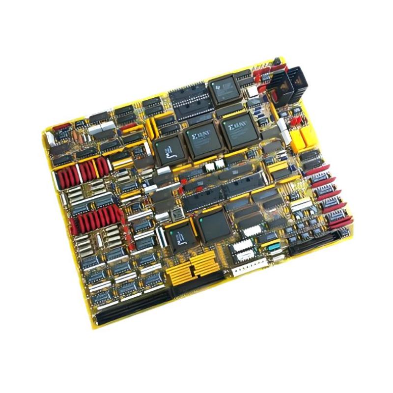
1. Product Overview
The **GE DS215TCQBG1BZZ01A (DS200TCQBG1BBA) Extended Analog I/O Board** is an industrial control circuit board associated with the GE Mark V Speedtronic turbine control system. It is designed to expand analog I/O capabilities and support signal handling in turbine control applications. The board is used in the R, S, and T control cores in applicable Mark V configurations. It is an optional extended I/O component rather than a universal replacement for every analog I/O board. In Simplex installations, the documented arrangement may require only one corresponding board in the R core. Actual hardware requirements depend on the turbine control architecture and installed configuration. The DS215TCQBG1BZZ01A designation identifies a special assembly associated with the DS200TCQBG1BBA functional board number. Because assembly revisions and firmware configurations can differ, both markings should be checked before installation or replacement. This guide covers preparation, identification, installation, configuration checks, commissioning, and maintenance considerations.
2. Technical Specifications
| Parameter | Description |
|---|---|
| Manufacturer | GE (General Electric) |
| Assembly Part Number | DS215TCQBG1BZZ01A |
| Functional Board Number | DS200TCQBG1BBA |
| Product Type | RST Extended Analog I/O Board |
| Functional Acronym | TCQB |
| Control System | GE Mark V Speedtronic |
| Primary Function | Extended analog I/O capability |
| System Architecture | Applicable R, S, and T control cores |
| Configuration | Depends on the installed turbine control system |
| Firmware and Memory | Verify the installed EPROM and board configuration |
The exact electrical ratings, terminal assignments, jumper positions, and environmental limits should be confirmed against the documentation for the specific board revision and turbine installation. Do not assume that information for another TCQB revision applies automatically.
3. Main Functions and Operating Principles
Extended Analog I/O Capability
The TCQB board provides additional analog I/O functionality within compatible Mark V configurations. It supports the acquisition and handling of selected analog signals used by the turbine control system. This expansion helps the system accommodate additional monitoring requirements without treating the board as a replacement for the main turbine control processor.
Signal Handling
Analog signals in a turbine control system may represent operating variables such as pressure, temperature, vibration-related measurements, or other process conditions. The exact signals assigned to the TCQB board depend on the installed hardware, field wiring, and application configuration.
RST Core Integration
The Mark V RST architecture uses multiple control cores to support the system’s control and availability strategy. Where the TCQB board is installed in R, S, and T cores, each board must correspond to the approved system configuration. A Simplex installation may use a different arrangement.
Configurable Hardware
The TCQB board includes hardware configuration elements. Certain applications involving proximity transducers or accelerometers may require specific jumper settings. These settings must be determined from the approved application documentation. Never copy jumper positions from another board simply because its part number looks similar.
4. Preparation Before Installation
Verify the Board Identity
Before opening the control cabinet, compare the replacement board with the installed unit. Check the following:
- Confirm the complete assembly number: DS215TCQBG1BZZ01A.
- Confirm the functional board number: DS200TCQBG1BBA.
- Check the revision markings and physical board layout.
- Inspect connectors, components, and the PCB for visible damage.
- Verify that the replacement is approved for the intended Mark V installation.
- Confirm whether the application uses Simplex or RST redundant architecture.
Do not select a replacement based only on the DS200TCQBG1B prefix. Different suffixes and special assemblies may have different hardware or configuration characteristics.
Record the Existing Installation
Before removing the original board, record its installed position and take clear photographs of the board label, cable routing, connector locations, and configuration elements. Label each cable so that it can be returned to its original connection. Record the existing firmware or EPROM arrangement where applicable. Some replacement assemblies may not include the memory devices fitted to the original board. Confirm the replacement’s supplied configuration before transferring any components.
Apply Electrical Safety Procedures
- Follow the plant’s approved shutdown and isolation procedure.
- Apply lockout/tagout where required.
- Verify that relevant control cabinet power sources are isolated.
- Allow stored electrical energy to discharge according to the equipment procedure.
- Use suitable ESD protection when handling the circuit board.
- Never remove or insert the board while energized unless an approved procedure explicitly permits that operation.
5. Installation Procedure
Step 1: Locate the Correct Board Position
Identify the TCQB board location using the Mark V cabinet drawings and the existing hardware arrangement. The board is associated with the extended analog I/O function and may occupy the designated position in the R, S, or T core, depending on the system configuration. Do not rely on a generic cabinet layout. Confirm the receiving position against the turbine-specific documentation.
Step 2: Remove the Existing Board
After completing isolation and safety checks, identify all connected cables and connectors. Label them before disconnection. Release the board retaining hardware using the appropriate procedure, then carefully remove the board without bending connectors or damaging adjacent components. Place the removed board in an antistatic protective package if it will be retained for inspection or repair.
Step 3: Inspect the Replacement Assembly
Compare the replacement with the removed board. Check the assembly number, functional number, revision, connector arrangement, component condition, and memory-device configuration. If EPROM devices need to be transferred, first confirm that the replacement instructions require this operation and that the devices are compatible. Record their original positions and orientation. Use appropriate ESD precautions and approved handling tools.
Step 4: Check Hardware Configuration
Review all configuration jumpers against the approved Mark V documentation for the specific turbine and board revision. Pay particular attention to applications involving proximity transducers or accelerometers, because input configuration can affect signal interpretation. Do not change jumper positions based on assumptions or generic online diagrams. An incorrect configuration can cause invalid measurements or unexpected control-system behavior.
Step 5: Install the Board
Align the board with the designated mounting position and carefully seat it in the correct interface. Secure it using the specified retaining hardware. Avoid excessive force and ensure that the PCB is not twisted or placed under mechanical stress.
Step 6: Reconnect Cables
Reconnect each cable to its documented position. Check connector orientation, locking features, cable condition, and seating. Make sure that no cable is trapped beneath the board or routed in a way that creates mechanical stress.
Step 7: Complete a Visual Inspection
Before restoring power, inspect the installation for loose hardware, disconnected cables, foreign objects, incorrect jumper settings, and possible contact between the board and adjacent components.
6. System Integration and Commissioning
After installation, commissioning should be performed by qualified personnel using the approved turbine-specific procedures.
Initial Power-Up Checks
Restore power according to the plant’s approved startup sequence. Observe the board’s status indication, if fitted, and check the Mark V diagnostic interface for board-related alarms or faults. Do not interpret a single LED indication as proof that all analog channels are operating correctly. Board status and channel-level signal validation are separate checks.
Verify Analog Signal Operation
Review the configured analog channels and compare the system readings with expected field conditions. Where practical, use approved test procedures and calibrated instruments to verify signal continuity and plausibility. Check for:
- Unexpected channel values or unstable readings.
- Open-circuit or wiring-related indications.
- Incorrect signal scaling or engineering units.
- Noise, grounding, or shielding problems.
- Differences between redundant control-core readings.
Confirm Redundant-Core Consistency
For applicable RST installations, compare the corresponding status and signal information across the configured control cores. Investigate discrepancies before returning the turbine to normal operation.
Functional Testing
Complete the required functional tests for the affected analog signals and turbine control functions. Verify alarms, interlocks, and related control responses according to the approved commissioning plan. Do not bypass protection functions or force outputs as a substitute for proper testing.
7. Maintenance and Long-Term Reliability
The DS215TCQBG1BZZ01A operates as part of a control system where stable analog signal handling is important to turbine monitoring and operation. Preventive maintenance should include:
- Inspecting the PCB and connectors during approved maintenance intervals.
- Checking for dust, contamination, corrosion, and signs of overheating.
- Reviewing diagnostic alarms and recurring channel faults.
- Checking cable seating and wiring condition.
- Maintaining records of board revisions and configuration changes.
- Keeping a correctly identified spare board in suitable antistatic storage.
Avoid unnecessary removal and reinsertion. Repeated handling can increase the risk of connector wear, electrostatic damage, or mechanical stress.
8. Common Installation Problems
| Observed Issue | Possible Cause | Recommended Check |
|---|---|---|
| Board not recognized | Incorrect seating, incompatible assembly, or interface issue | Verify board identity, receiving position, and connector engagement. |
| Board diagnostic alarm | Hardware, configuration, or communication-related fault | Review system diagnostics and revision-specific troubleshooting instructions. |
| Incorrect analog readings | Wiring, signal configuration, scaling, or jumper mismatch | Check the approved channel configuration and field wiring. |
| Unstable signal values | Electrical noise, grounding problems, or field-device issues | Inspect shielding, grounding, cable routing, and signal sources. |
| RST core disagreement | Different configurations, signal paths, or hardware conditions | Compare corresponding core diagnostics and configuration records. |
9. Frequently Asked Questions
What is the GE DS215TCQBG1BZZ01A used for?
It is a special assembly associated with the DS200TCQBG1BBA RST Extended Analog I/O Board. It provides extended analog I/O capability in compatible GE Mark V turbine control systems.
Are DS215TCQBG1BZZ01A and DS200TCQBG1BBA the same part number?
They identify related assembly and functional board designations. They should not be treated as interchangeable descriptions without checking the complete board markings, revision, and installed configuration.
Can this board be installed in any Mark V cabinet?
No. Its use depends on the turbine control architecture, designated board position, wiring, and approved system configuration.
Does the board require jumper configuration?
Hardware configuration elements are present. The correct settings depend on the application and connected devices. Follow the exact revision-specific documentation rather than using assumed settings.
Can the EPROM devices from an old board be transferred?
Transfer may be required for some replacement arrangements, but it must be confirmed against the replacement assembly instructions. Verify device identity, compatibility, orientation, and original location before handling.
What should be checked after installation?
Check board recognition, diagnostic status, analog signal plausibility, configured channel operation, and consistency across the applicable RST cores.
10. Technical Summary
The GE DS215TCQBG1BZZ01A (DS200TCQBG1BBA) is an RST Extended Analog I/O Board assembly designed for compatible GE Mark V Speedtronic turbine control applications. Correct installation requires careful part-number and revision verification, preservation of the original wiring and memory configuration, application-specific jumper checks, and compliance with electrical safety procedures. A successful replacement is not established by physical installation alone. Board diagnostics, analog signal validation, and applicable redundant-core checks must also be completed before the affected equipment is returned to service.