

ProductPRODUCT
Featured products



Contact Us
- Ingersoll Rand
- 47629378001 24107948
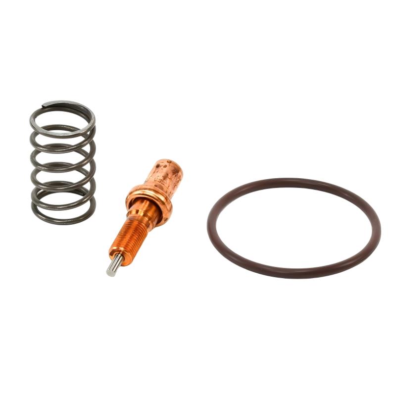
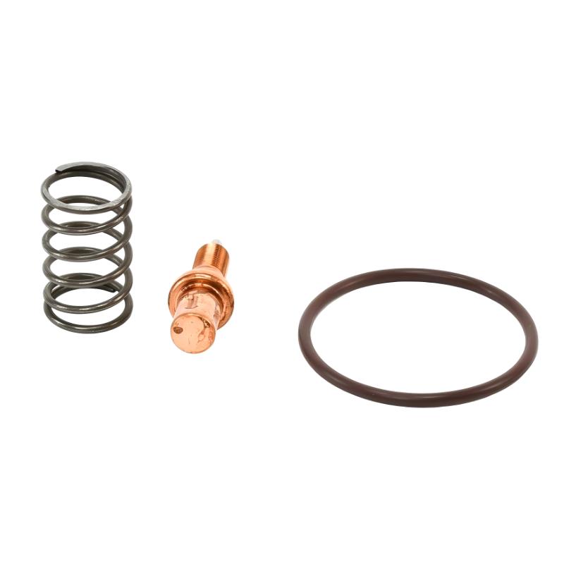
- Temperature Control Valve Service Kit
- USA
- 100 × 15 × 80 mm
- 0.15 kg
- Xiamen, China
- New & In Stock
- T/T, PayPal, Western Union
- 1 Year
- 1-3 Working Days
- DHL, UPS, TNT, FedEx and EMS.
- 24-Hour Service
- COO
- 6
Our advantage

Global Logistics
We have a 10-year logistics and express cooperation agreement, so our products can be shipped to any place in the world.

Brand new and original
Our products are imported in bulk from the place of origin. Because of the cooperative relationship, our products are all original and 100% new.

24-hour service
We provide 7*24 hours service to our customers. We will be there whenever you need us.

Price advantage
All our products are priced very favorably because we have our own warehouse and supply.
| Company Information | |||
| [email protected] | |||
| Mobile | +8615980777398 | ||
| +8615980777398 | |||
| 15980777398 |
Product Overview
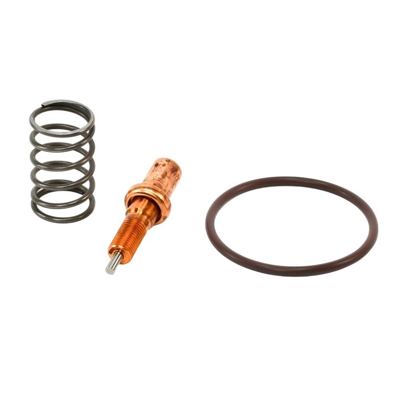
The Ingersoll Rand 47629378001 24107948 Temperature Control Valve Service Kit is a maintenance kit for servicing the high-speed temperature control valve (HSTCV) used in compatible Ingersoll Rand compressor equipment. The identified valve configuration uses a 51 mm specification, an M27 connection, and a temperature range of 180–198°F. These details are important when selecting a replacement kit because temperature control valve assemblies can differ in their internal components, connection arrangements, and operating characteristics.
In oil-injected compressor systems, lubricant temperature affects more than cooling performance. The oil must remain within an appropriate operating range to support lubrication, heat removal, and the separation of moisture from the circulating lubricant. The temperature control valve manages oil flow through the cooling circuit according to the thermal conditions of the system. When the oil is cold, the valve arrangement can direct flow differently than when the oil reaches its operating temperature.
A service kit allows maintenance personnel to service the designated valve assembly without automatically replacing the complete valve housing or surrounding pipework. This is useful during compressor maintenance when inspection identifies wear, sticking, leakage, or temperature regulation problems associated with the valve mechanism.
The 24107948 part number identifies the HSTCV service configuration rather than a generic thermostat kit. Before installation, technicians should confirm the existing valve specification, including the 51 mm–M27 configuration and the stated temperature range. Selecting a kit solely because it is described as a temperature control valve service kit can result in mismatched internal components or incorrect valve operation.
Technical Specifications
| Parameter | Specification |
|---|---|
| Manufacturer | Ingersoll Rand |
| Product Type | Temperature Control Valve Service Kit |
| Part Number | 47629378001 |
| Component Number | 24107948 |
| Valve Type | High-Speed Temperature Control Valve (HSTCV) |
| Valve Specification | 51 mm–M27 |
| Temperature Range | 180–198°F |
| Application | Compressor temperature control valve maintenance |
| Dimensions | 100 × 15 × 80 mm |
| Weight | 0.15 kg |
Product Features
- Temperature-specific configuration: Identified for an HSTCV arrangement with a stated operating range of 180–198°F.
- Defined valve specification: The 51 mm–M27 designation helps distinguish the intended service configuration from other valve variants.
- Valve servicing: Supports maintenance of the designated temperature control valve assembly without automatically replacing the entire assembly.
- Lubricant temperature management: Supports the valve’s role in directing oil through the compressor cooling circuit.
- Targeted maintenance: Allows technicians to address valve-related wear or operating problems identified during inspection.
- Configuration-based replacement: Requires matching the kit specification to the installed valve rather than relying on the compressor brand alone.
- Cooling circuit maintenance: Provides an opportunity to inspect related oil passages, connections, and sealing surfaces during servicing.
Working Principle
The 24107948 service kit is associated with a high-speed temperature control valve that regulates lubricant flow according to temperature. In an oil-injected compressor, circulating oil absorbs heat during compression and carries it toward the cooling system. The temperature control valve helps determine whether the oil flows through the cooler or follows a bypass route, depending on the valve design and operating temperature.
The general oil flow arrangement is:
Compressor Airend → Oil Separation and Recovery Circuit → Temperature Control Valve → Oil Cooler or Bypass Path → Lubrication Circuit
When the lubricant is below the valve’s intended operating range, the valve can direct a greater proportion of oil through the bypass path, reducing cooling during warm-up. As the oil temperature rises, the valve changes position to direct more oil through the cooler. This helps the compressor approach and maintain its intended operating temperature.
The 24107948 kit is used to service the specified valve mechanism. The exact internal arrangement depends on the HSTCV design, but service work may involve renewing the applicable internal components and seals included in the kit. The complete kit contents should be confirmed before maintenance because the part number alone does not establish every component supplied.
If the valve sticks, fails to respond correctly to temperature, or develops an internal leak, oil flow through the cooling circuit may no longer follow the intended pattern. The result can be slow warm-up, excessive oil temperature, or inconsistent temperature regulation. However, similar symptoms can also arise from a restricted cooler, inadequate airflow, incorrect lubricant level, or other cooling circuit faults. Diagnosis should therefore include the surrounding system rather than assuming the valve is always the cause.
Role in the Compressor Temperature Control System
The temperature control valve sits within the compressor’s lubricant circulation circuit. Its function is to manage oil routing as operating temperature changes, helping balance warm-up requirements with heat removal during normal operation.
Oil Separation and Recovery → Temperature Control Valve → Oil Cooler / Bypass Path → Oil Filter, Where Fitted → Compressor Airend
| System Element | Function |
|---|---|
| Compressor Airend | Generates heat during the compression process |
| Oil Separation and Recovery Circuit | Returns lubricant for recirculation |
| Temperature Control Valve | Regulates oil routing according to temperature |
| Valve Service Kit 24107948 | Supports servicing of the specified HSTCV assembly |
| Oil Cooler | Removes heat from circulating lubricant |
| Oil Filter | Removes contaminants from the lubricant where fitted in the circuit |
| Oil Lines and Connections | Carry lubricant between the relevant components |
| Temperature Monitoring | Helps maintenance personnel assess operating conditions |
The precise routing sequence varies by compressor design. Valve servicing must preserve the original circuit arrangement and the specified temperature-control characteristics.
Industrial Applications
| Application | Typical Use |
|---|---|
| Industrial Rotary Screw Compressors | Servicing the lubricant temperature control valve in compatible oil-injected systems |
| Centrifugal Compressor Maintenance | Maintaining compatible high-speed temperature control valve assemblies where specified |
| Manufacturing Facilities | Maintaining compressor cooling performance in plant air systems |
| Continuous-Duty Compressor Installations | Addressing valve-related temperature regulation issues during planned maintenance |
| Compressor Overhauls | Renewing serviceable internal valve components during a scheduled overhaul |
| Cooling Circuit Troubleshooting | Investigating temperature behavior associated with valve operation |
| Preventive Maintenance Programs | Inspecting the temperature control valve and related oil circuit components |
| Industrial Compressed-Air Systems | Maintaining the temperature control arrangement required by the compressor configuration |
The kit is suitable only for valve assemblies that match its specified configuration. Its use in a particular compressor must be established from the installed valve specification and equipment parts information.
Installation and Maintenance
- Verify the kit identification: Confirm that 47629378001 and 24107948 correspond to the required service kit and that the installed valve matches the 51 mm–M27 specification.
- Confirm the temperature rating: Check that the 180–198°F configuration matches the existing valve and the compressor’s specified operating requirements.
- Shut down and isolate the compressor: Follow the equipment’s lockout procedure and isolate all relevant energy sources before beginning work.
- Allow the system to cool: Wait until the lubricant and valve assembly have reached a safe temperature for maintenance.
- Release stored pressure: Depressurize the relevant circuit according to the approved service procedure before loosening connections or opening the valve.
- Record the original arrangement: Note the valve orientation, connected oil lines, and component positions before disassembly.
- Inspect the valve housing: Check the accessible housing surfaces, threads, and sealing interfaces for damage, contamination, or evidence of leakage.
- Examine the internal components: Follow the valve-specific service procedure to check for wear, sticking, deposits, or damaged sealing elements.
- Verify the kit contents: Confirm that the required service components are present and suitable for the valve being serviced.
- Install the service components: Fit the applicable parts according to the specified assembly sequence, ensuring that sealing elements and moving components are correctly positioned.
- Reassemble and test the circuit: Follow the prescribed tightening requirements, restore the system under the approved procedure, and check for leaks and abnormal temperature behavior.
- Record the service results: Document the kit part number, maintenance date, observed valve condition, and any follow-up checks required.
Do not open a hot or pressurized oil circuit. If temperature regulation remains abnormal after servicing, check the cooler, oil flow path, lubricant condition, and other relevant components before replacing the valve again.
Compatible System Components
The 24107948 service kit is associated with the high-speed temperature control valve assembly. The following component types are relevant to the surrounding lubricant temperature control circuit, depending on the compressor design.
| Component | Function |
|---|---|
| High-Speed Temperature Control Valve | Regulates lubricant routing in response to temperature |
| Oil Cooler | Removes heat from circulating lubricant |
| Oil Filter | Filters lubricant before it returns to the designated circuit |
| Oil Lines and Fittings | Carry oil between the valve, cooler, and other components |
| Compressor Airend | Produces the heat that the lubricant and cooling circuit must manage |
| Oil Separator Assembly | Separates lubricant from compressed air and supports oil recovery |
| Temperature Sensor | Monitors oil or system temperature where fitted |
| Valve Seals and Internal Service Components | Support the sealing and movement of the serviced valve assembly |
Recommended Related Models
| Model | Product Type | Relevance |
|---|---|---|
| Ingersoll Rand 24106023 | Temperature Control Valve Assembly | Related valve component for temperature regulation |
| Ingersoll Rand 23551831 | Temperature Control Valve Service Kit | Another service kit for a temperature control valve configuration |
| Ingersoll Rand 23710842 | Thermal Valve Kit | Related thermal valve maintenance component |
| Ingersoll Rand 24509184 | Temperature Control Valve Repair Kit | Related valve repair component requiring configuration verification |
| Ingersoll Rand 23879133 | Temperature Control Valve | Related temperature control component |
| Ingersoll Rand 24176992 | Minimum Pressure Valve Service Kit | Related compressor service kit for a separate pressure-control function |
Key Advantages
- Supports servicing of the specified HSTCV assembly.
- Preserves the valve’s intended temperature-control function when correctly matched and installed.
- Allows targeted maintenance without automatically replacing the complete valve assembly.
- Helps address valve-related oil routing and temperature regulation problems.
- Provides a distinct part number for service-kit identification.
Technical FAQs
What does the 51 mm–M27 specification mean for the 24107948 service kit?
It identifies the intended HSTCV configuration. The valve dimensions and connection specification must match the installed assembly; a kit with a different configuration should not be selected solely because the product name is similar.
What is the significance of the 180–198°F temperature range?
This is the stated temperature range associated with the identified service-kit configuration. It is relevant when matching the kit to the existing temperature control valve. It should not be interpreted as a universal compressor operating-temperature limit.
Can the 24107948 kit correct an overheating compressor?
It may address overheating caused by a faulty temperature control valve, but overheating can also result from restricted cooler airflow, inadequate oil flow, a contaminated cooler, or other system problems. Diagnose the cooling circuit before deciding that the service kit is the required repair.
Does installing the service kit require replacement of the entire temperature control valve?
Not necessarily. A service kit is intended to service the specified valve assembly. Whether the existing housing can be retained depends on its condition, the kit’s contents, and the applicable service procedure. A damaged housing or a fault outside the kit’s scope may require additional parts.