

ProductPRODUCT
Featured products
Contact Us
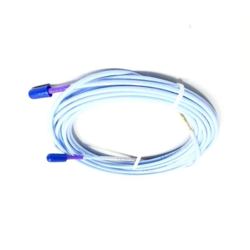
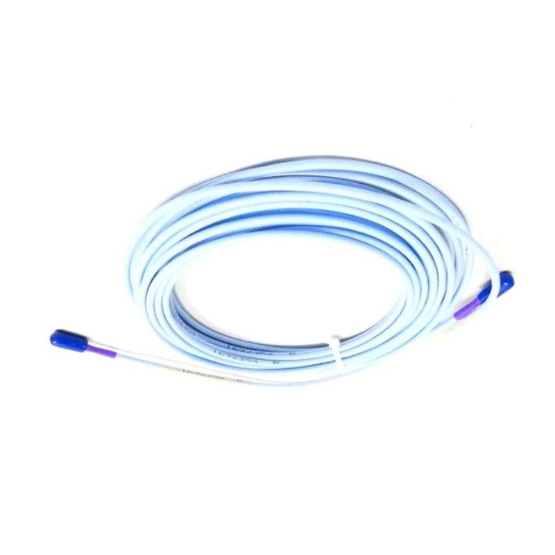
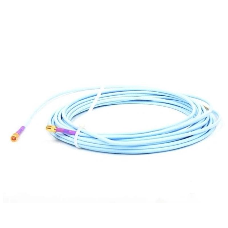
- Bently Nevada
- 330730-080-10-05
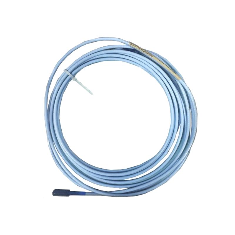
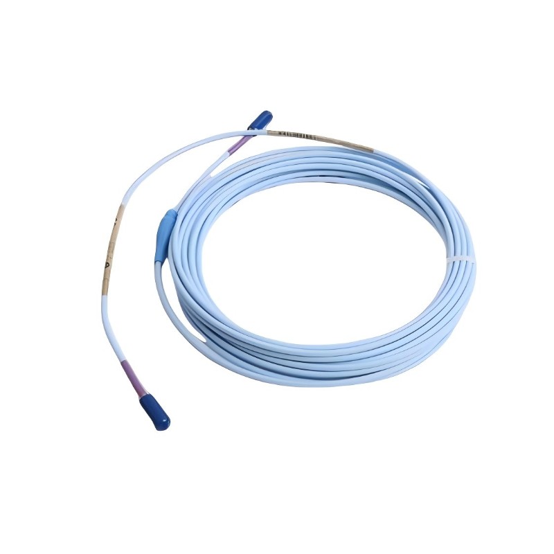
- 3300 XL 11mm Extension Cable
- USA
- 8.0 m
- 0.36kg
- Xiamen, China
- New & In Stock
- T/T, PayPal, Western Union
- 1 Year
- 1-3 Working Days
- DHL, UPS, TNT, FedEx and EMS.
- 24-Hour Service
- COO
- 2
Our advantage

Global Logistics
We have a 10-year logistics and express cooperation agreement, so our products can be shipped to any place in the world.

Brand new and original
Our products are imported in bulk from the place of origin. Because of the cooperative relationship, our products are all original and 100% new.

24-hour service
We provide 7*24 hours service to our customers. We will be there whenever you need us.

Price advantage
All our products are priced very favorably because we have our own warehouse and supply.
| Company Information | |||
| [email protected] | |||
| Mobile | +8615980777398 | ||
| +8615980777398 | |||
| 15980777398 |
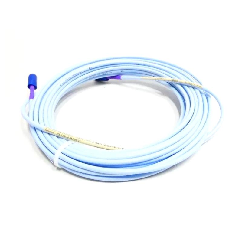
Bently Nevada 330730-080-10-05 Extension Cable — Product Overview and Technical Specifications
1. Product Overview
The Bently Nevada 330730-080-10-05 is an extension cable in the 3300 XL 11 mm proximity transducer system. It is designed to connect a compatible proximity probe to its associated Proximitor Sensor, carrying the measurement signal through the monitoring circuit.
This cable is intended for industrial machinery condition monitoring, where reliable measurement of shaft vibration, relative shaft displacement, and other mechanical movement is important to equipment operation and maintenance.
The model code identifies an 8.0-metre cable, a FluidLoc cable construction, and a multiple-agency approval option. The cable forms part of a matched measurement system, so its electrical characteristics and total system length should be considered alongside the probe and Proximitor Sensor rather than selecting it by physical length alone.
2. Basic Product Information
| Parameter | Specification |
|---|---|
| Brand | Bently Nevada |
| Model | 330730-080-10-05 |
| Product name | 3300 XL 11 mm Extension Cable |
| Product category | Industrial sensor extension cable |
| Product series | 3300 XL 11 mm Proximity Transducer System |
| Cable length code | 080 |
| Nominal cable length | 8.0 m |
| Length in feet | Approximately 26.2 ft |
| Cable construction code | 10 |
| Cable type | FluidLoc extension cable |
| Approval code | 05 |
| Approval configuration | Multiple-agency approval option; applicable approvals depend on the supplied configuration |
| Typical application | Proximity probe signal connection and machinery condition monitoring |
| System type | Eddy-current proximity measurement system |
| Compatible equipment | Appropriate 3300 XL 11 mm probes and matching Proximitor Sensors, subject to system-length and compatibility checks |
| Typical installation location | Industrial machinery, monitoring cabinets, and field cable routes |
| Cable weight | Approximately 0.36 kg for 8.0 m, based on the standard-cable reference value; confirm the supplied configuration |
| Overall shipping weight | Not fixed; depends on packaging and accessories |
| Cable dimensions | Nominal length: 8.0 m; exact outer diameter and connector dimensions require the applicable product drawing |
| Operating temperature | Commonly specified for this cable family as approximately −51°C to +177°C; confirm the exact order-code documentation |
| Electrical design | Matched extension cable for the applicable proximity measurement system |
| Installation type | Pre-terminated cable assembly |
| Maintenance approach | Inspect cable jacket, connectors, routing, and signal stability periodically |
Important technical note: The final suffix 05 denotes the multiple-agency approval option in this product family. It should not be taken as proof of a particular certification for every supplied unit. For safety-critical or hazardous-area installations, verify the approval markings and the exact documentation accompanying the cable.
3. Detailed Technical Parameters
The 330730-080-10-05 is an extension cable rather than an active sensor. It does not independently measure vibration or generate a measurement output. Instead, it provides the electrical connection required for the compatible probe and Proximitor Sensor to operate as a complete measurement channel.
| Technical item | Parameter / description |
|---|---|
| Full model number | 330730-080-10-05 |
| Measurement system | 3300 XL 11 mm proximity transducer system |
| Cable length | 8.0 m |
| Approximate length | 26.2 ft |
| Cable type | FluidLoc |
| Cable option | 10 |
| Agency approval option | 05 — multiple approvals |
| Nominal cable impedance | 75 Ω triaxial design |
| Typical cable capacitance | Approximately 69.9 pF/m |
| Typical core DC resistance | Approximately 2.0 ± 0.5 Ω for an 8 m assembly |
| Typical jacket-path DC resistance | Approximately 0.6 ± 0.2 Ω for an 8 m assembly |
| Signal transmission | Carries the proximity probe signal to the compatible Proximitor Sensor |
| Sensing principle | Eddy-current proximity measurement, as part of the complete transducer system |
| Cable jacket | FluidLoc construction; verify the supplied material specification |
| Connector arrangement | Compatible ClickLoc-style connections within the applicable system configuration |
| Nominal operating temperature | Approximately −51°C to +177°C for the cable family; verify exact documentation |
| Cable weight reference | Approximately 0.36 kg for 8.0 m of standard cable |
| Overall product weight | Confirm against the actual supplied configuration |
| Cable length tolerance | Refer to the applicable technical drawing |
| Cable outside diameter | Not confirmed for this exact configuration |
| Connector dimensions | Not confirmed for this exact configuration |
| Shipping dimensions | Depend on packaging and shipping method |
| Power consumption | Passive cable assembly; no independent power consumption |
| Calibration role | Preserves the intended electrical characteristics of the matched measurement circuit |
| Installation environment | Industrial machinery monitoring installations, subject to the system’s environmental and approval requirements |
| Typical maintenance | Connector inspection, cable-jacket inspection, routing checks, and electrical continuity testing |
Understanding the main electrical specifications
75 Ω triaxial construction
The cable’s electrical design is intended to work with the compatible proximity measurement circuit. Correct impedance and cable characteristics help preserve the measurement signal and reduce problems caused by unsuitable replacement wiring.
Typical capacitance of 69.9 pF/m
Cable capacitance affects the electrical characteristics of the complete probe-cable-Proximitor combination. A replacement cable should therefore be selected according to the system’s specified configuration rather than on length alone.
8.0 m cable length
The 080 code identifies the nominal 8.0 m cable length. The cable length must be considered together with the probe cable length and the Proximitor Sensor’s specified system length. An incorrect combination may produce measurement errors or prevent the system from operating within its intended range.
FluidLoc cable construction
The 10 option identifies the FluidLoc cable configuration. It is intended for industrial measurement applications where cable construction and environmental resistance matter. The exact resistance to particular oils, chemicals, mechanical loads, and environmental conditions should be checked against the applicable product documentation.
Multiple-agency approval option
The 05 suffix identifies a multiple-approval ordering option. Actual approvals and their scope should be confirmed on the delivered product and accompanying records before installation in a regulated or hazardous area.
4. Product Description
The Bently Nevada 330730-080-10-05 extension cable is a component of an industrial proximity measurement system used to monitor the mechanical condition of rotating machinery. It connects the compatible probe assembly to the associated Proximitor Sensor, providing the required signal path between the sensing point and the monitoring electronics.
In a typical installation, the probe is positioned near a conductive rotating shaft. As the distance between the probe tip and the shaft changes, the probe and Proximitor Sensor convert the resulting electrical response into a signal that can be used to determine shaft displacement or vibration.
The extension cable plays an important supporting role in this process. Although it does not directly measure shaft movement, the cable’s length, electrical characteristics, connector condition, and routing influence the performance of the complete measurement loop.
The 8.0 m configuration is useful where the physical distance between the probe installation and the associated signal-conditioning equipment calls for a longer cable assembly. The final choice should account for the actual equipment layout, cable routing, and total system-length requirements.
The FluidLoc construction and pre-terminated connector arrangement are intended to simplify installation compared with assembling a cable from separate field components. Correct part-number matching remains important, especially where the equipment is used for continuous monitoring or machinery protection.
5. Product Applications
5.1 Steam turbines
Steam turbines rely on accurate machinery measurements to help operators identify abnormal shaft movement, changing vibration levels, and potential mechanical deterioration.
When installed in a compatible proximity measurement loop, the 330730-080-10-05 carries the signal from the probe to the Proximitor Sensor. The resulting measurement can then be passed to the appropriate monitoring equipment.
The cable itself does not provide turbine protection, but it supports the signal path used by the larger monitoring system.
5.2 Gas turbines
Gas turbines operate under demanding mechanical and thermal conditions. Reliable monitoring instrumentation is important for identifying developing problems and supporting maintenance planning.
The extension cable can be used in a compatible shaft proximity measurement arrangement, provided its cable routing, environmental exposure, and system compatibility meet the installation requirements.
5.3 Centrifugal compressors
Centrifugal compressors are commonly monitored for shaft vibration and relative shaft displacement. Changes in these measurements can help maintenance teams investigate rotor instability, bearing-related problems, alignment issues, or other developing mechanical conditions.
The extension cable connects the measurement components and helps preserve the intended electrical characteristics of the proximity system.
5.4 Pumps and other rotating machinery
Industrial pumps, motors, and other rotating equipment may use proximity measurements where the machine design and monitoring requirements call for them.
The cable can be appropriate for such installations when the probe, Proximitor Sensor, cable length, and monitoring equipment are all compatible. Not every pump or motor uses an eddy-current proximity system, so the actual instrumentation design must be checked before selecting this component.
5.5 Industrial machinery monitoring systems
The cable may also be used in broader industrial condition-monitoring installations that incorporate compatible proximity sensors and machinery monitoring hardware.
Typical objectives include continuous measurement, trend analysis, identification of abnormal operating conditions, and support for maintenance decisions. The quality of these functions depends on the complete measurement system, installation quality, and the monitoring equipment’s configuration.
6. Product Advantages
6.1 Supports reliable signal transmission
The extension cable is designed for use in a defined proximity measurement system. Maintaining the specified cable characteristics helps the connected probe and Proximitor Sensor operate as intended.
Using the correct cable type is particularly important when replacing a cable in an existing measurement channel, because an electrically different cable may affect system performance.
6.2 Provides a practical 8.0 m connection length
The 8.0 m length provides additional routing flexibility when the probe and associated electronics are not close together.
This can help accommodate machinery layouts, equipment cabinets, and cable tray arrangements while avoiding unnecessary intermediate connections.
6.3 FluidLoc cable option
The FluidLoc configuration provides a defined cable construction for industrial use. This may be beneficial in installations where the cable must be routed through an environment that requires suitable jacket and material characteristics.
Environmental suitability should still be assessed against the actual operating conditions, including temperature, chemical exposure, movement, and mechanical protection requirements.
6.4 Pre-terminated connection design
A factory-assembled cable can reduce the need for field termination and the associated risk of incorrect wiring or inconsistent assembly.
The installer should nevertheless inspect the connectors, verify the part number, and follow the specified connection and handling procedure.
6.5 Supports continuous machinery monitoring
When used in a correctly configured measurement loop, the cable supports the transmission of measurements that monitoring equipment can use for trend analysis and machinery diagnostics.
This is useful for facilities that need consistent data over extended operating periods. It does not guarantee fault detection on its own; the complete monitoring system must be configured, maintained, and interpreted correctly.
6.6 Multiple-agency approval option
The 05 configuration is intended for orders requiring multiple-agency approvals. This can be relevant to industrial projects with defined compliance requirements.
The precise certification status must be verified for the actual item supplied. The suffix alone should not replace the required inspection of markings and documentation.
6.7 Supports replacement and maintenance work
An exact replacement cable can simplify maintenance by preserving the intended cable length and configuration.
For replacement work, the original installed part number should be compared with the proposed cable, and the entire probe-cable-Proximitor combination should be checked before the machinery is returned to service.
7. Brand and Product Series
| Item | Description |
|---|---|
| Brand | Bently Nevada |
| Series | 3300 XL |
| Product family | 11 mm Proximity Transducer System |
| Product type | Extension cable |
| Primary function | Connects a compatible proximity probe to its Proximitor Sensor |
| Measurement technology | Eddy-current proximity measurement system |
| Typical equipment | Rotating machinery and industrial condition-monitoring installations |
| Related components | Compatible 3300 XL 11 mm proximity probes, Proximitor Sensors, and machinery monitoring equipment |
The 3300 XL 11 mm family is intended for proximity measurements in machinery applications. The probe, extension cable, and Proximitor Sensor form a matched electrical system, so the correct component selection is essential.
The 330730-080-10-05 should therefore be treated as one part of a complete measurement channel, rather than as a standalone vibration sensor.
8. Recommended Related Models in the Same Series
The following five models are related options for comparison. Some differ in cable length, construction, or approval configuration; others are associated components used in the same measurement system. They are not all direct, interchangeable replacements.
| Model | Product type / configuration | Key parameters | Dimensions | Weight (kg) |
|---|---|---|---|---|
| 330730-080-10-00 | 3300 XL 11 mm FluidLoc extension cable | 8.0 m; FluidLoc option; approval option 00 | Cable length 8.0 m; connector dimensions not confirmed | Approx. 0.36 kg, standard-cable reference |
| 330730-080-12-05 | FluidLoc extension cable with connector protectors | 8.0 m; FluidLoc construction; connector-protector option; multiple-approval option | Cable length 8.0 m; exact overall dimensions not confirmed | Not confirmed |
| 330730-080-13-05 | Armored FluidLoc extension cable with connector protectors | 8.0 m; armored FluidLoc configuration; connector protectors; multiple-approval option | Cable length 8.0 m; armor and connector dimensions require drawing | Not confirmed |
| 330730-040-10-05 | FluidLoc extension cable | 4.0 m; FluidLoc construction; multiple-approval option | Cable length 4.0 m; exact overall dimensions not confirmed | Not confirmed |
| 330730-080-11-05 | Armored FluidLoc extension cable | 8.0 m; armored FluidLoc configuration; multiple-approval option | Cable length 8.0 m; exact overall dimensions not confirmed | Not confirmed |
Selection guidance: The model code and options must be confirmed before ordering. In particular, verify that the proposed variant is an available configuration for the required application. The approximate 0.36 kg value above is a standard-cable reference, not a verified weight for every cable option.
9. Five Other Popular Models from the Same Brand
The following models are useful for comparing other components in the brand’s machinery-monitoring product range. They perform different functions, so they should not be considered direct substitutes for the 330730-080-10-05.
| Model | Product name / type | Main parameters and function | Dimensions | Weight (kg) |
|---|---|---|---|---|
| 330101-00-08-10-02-00 | 3300 XL 8 mm proximity probe | Probe component for compatible 3300 XL 8 mm measurement systems; exact probe length and thread configuration depend on the order code | Probe-body dimensions depend on configuration; verify drawing | Not confirmed |
| 330103-00-08-10-02-00 | 3300 XL 8 mm proximity probe | Probe component used in compatible proximity measurement applications; confirm the full configuration and system compatibility | Probe-body dimensions depend on configuration; verify drawing | Not confirmed |
| 330104-00-08-10-02-00 | 3300 XL 8 mm proximity probe | Proximity probe model for applicable machinery measurement arrangements; electrical matching and installation geometry must be checked | Probe-body dimensions depend on configuration; verify drawing | Not confirmed |
| 330180-50-00 | Proximitor Sensor | Signal-conditioning component for a compatible proximity transducer system; confirm the required system variant and mounting arrangement | Exact housing and mounting dimensions require the applicable drawing | Not confirmed |
| 3500/42M | Machinery monitoring module | Monitoring module used in compatible machinery protection and condition-monitoring architectures; channel configuration and rack compatibility must be checked | Rack-mounted module; exact dimensions depend on the applicable hardware specification | Not confirmed |
These products serve different purposes within a machinery-monitoring installation. A proximity probe detects changes in the distance between its tip and the target; a Proximitor Sensor conditions the probe signal; and a monitoring module processes measurements within the wider monitoring architecture.
The model numbers listed above are comparison candidates, not a declaration that they can be connected directly to the 330730-080-10-05. Verify the exact order code, system family, and technical documentation before procurement.
10. Installation and Maintenance Considerations
Before installation
1. Confirm that the full cable part number matches the intended installation.
2. Verify the cable length and total system-length requirements for the probe and Proximitor Sensor.
3. Inspect the connectors for contamination, damage, or bent contacts.
4. Check the cable route for sharp edges, excessive bending, hot surfaces, and possible mechanical abrasion.
5. Confirm that the supplied approval configuration meets the installation’s compliance requirements.
During installation
1. Follow the applicable installation instructions for the connector and cable assembly.
2. Route the cable to minimize exposure to mechanical damage and avoid unsuitable proximity to high-interference wiring.
3. Do not cut, splice, or alter the cable unless the manufacturer’s instructions explicitly permit the proposed work.
4. Avoid applying excessive force to the connector or cable entry points.
5. Maintain the specified cable routing and grounding arrangements for the complete measurement system.
After installation
1. Verify that the cable is securely connected at both ends.
2. Check continuity and other electrical characteristics using the approved test procedure.
3. Confirm that the monitoring channel produces plausible readings under the specified commissioning conditions.
4. Review the monitoring system’s diagnostic status before returning the equipment to service.
5. Record the installed part number and configuration for future maintenance.
Routine inspection
Periodic inspections should focus on cable-jacket condition, connector integrity, routing security, and any intermittent or abnormal measurement behavior. If the cable is suspected of causing signal instability, verify the complete measurement loop before replacing components.
11. Dimensions and Weight: Purchasing Reference
| Item | Reference value |
|---|---|
| Nominal cable length | 8.0 m |
| Equivalent length | Approximately 26.2 ft |
| Cable weight reference | Approximately 0.36 kg for a standard 8.0 m cable |
| Exact weight of model 330730-080-10-05 | Should be confirmed against the supplied configuration |
| Cable outside diameter | Not confirmed |
| Connector length and diameter | Not confirmed |
| Packed product dimensions | Depend on packaging |
| Packed shipping weight | Depends on packaging and shipping materials |
For procurement, it is important to distinguish cable length, net product weight, and shipping weight. The cable length is identifiable from the model code, but the exact dimensions and weight of the complete supplied assembly should be confirmed against its product drawing or packing specification.
12. Summary
The Bently Nevada 330730-080-10-05 is an 8.0 m FluidLoc extension cable in the 3300 XL 11 mm proximity transducer family. Its primary role is to connect a compatible proximity probe and Proximitor Sensor while maintaining the electrical characteristics required by the measurement system.
Its main selection considerations are the cable length, FluidLoc configuration, multiple-agency approval option, connector compatibility, and correct matching with the rest of the measurement loop.
For purchasing or replacement, the most important checks are the complete part number, required approvals, system-length compatibility, and exact physical specifications. The approximate 0.36 kg value is a standard-cable reference; the precise weight and connector dimensions of the ordered configuration should be confirmed before finalizing a specification sheet or shipping arrangement.