

ProductPRODUCT
Featured products
Contact Us
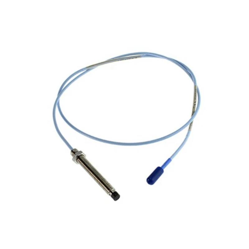
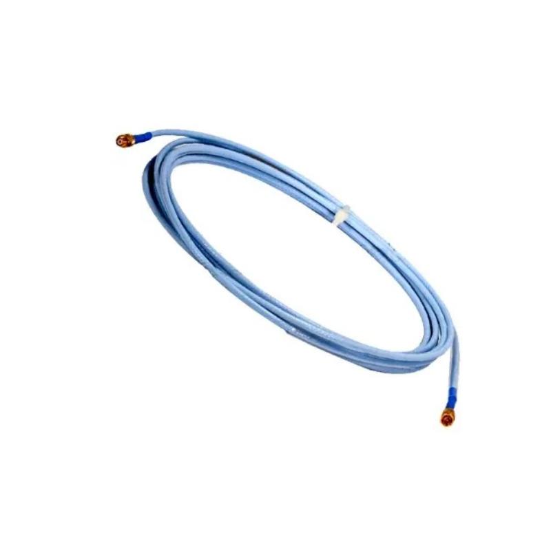
- Bently Nevada
- 330730-080-10-00
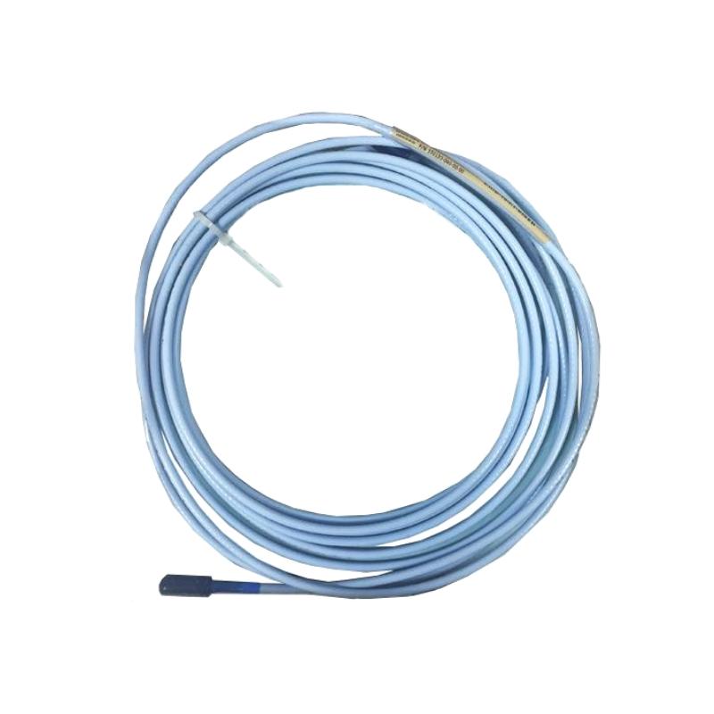
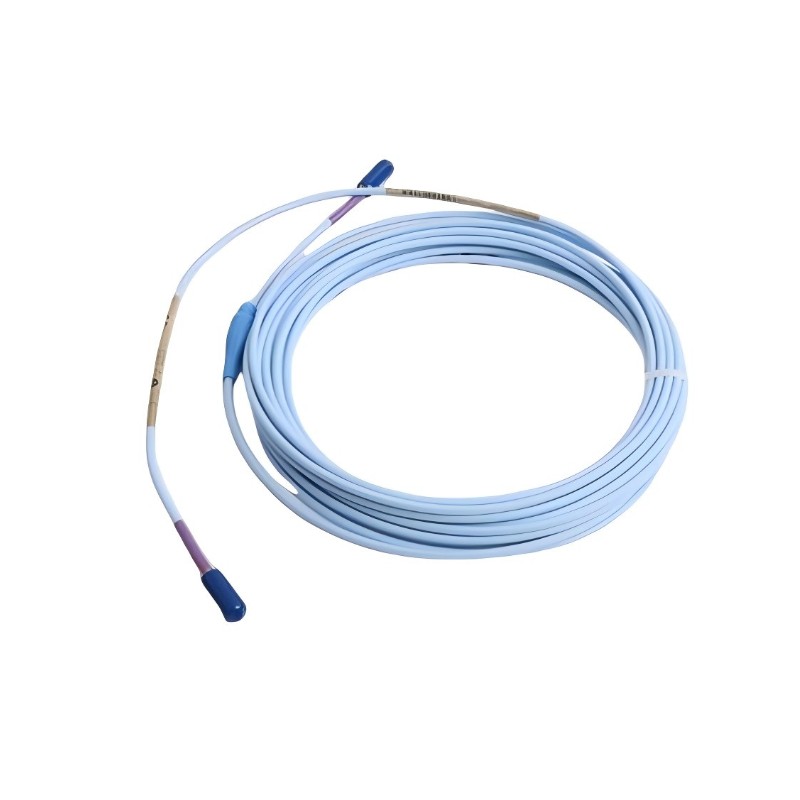
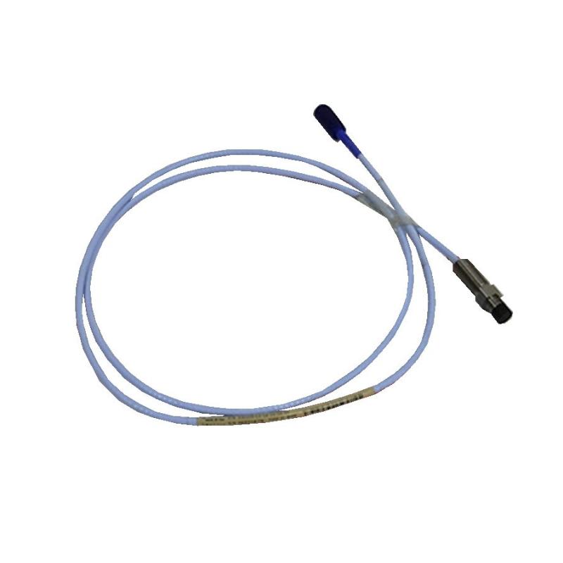
- 3300 XL 11mm Extension Cable
- USA
- 8.0 m
- 1kg
- Xiamen, China
- New & In Stock
- T/T, PayPal, Western Union
- 1 Year
- 1-3 Working Days
- DHL, UPS, TNT, FedEx and EMS.
- 24-Hour Service
- COO
- 3
Our advantage

Global Logistics
We have a 10-year logistics and express cooperation agreement, so our products can be shipped to any place in the world.

Brand new and original
Our products are imported in bulk from the place of origin. Because of the cooperative relationship, our products are all original and 100% new.

24-hour service
We provide 7*24 hours service to our customers. We will be there whenever you need us.

Price advantage
All our products are priced very favorably because we have our own warehouse and supply.
| Company Information | |||
| [email protected] | |||
| Mobile | +8615980777398 | ||
| +8615980777398 | |||
| 15980777398 |
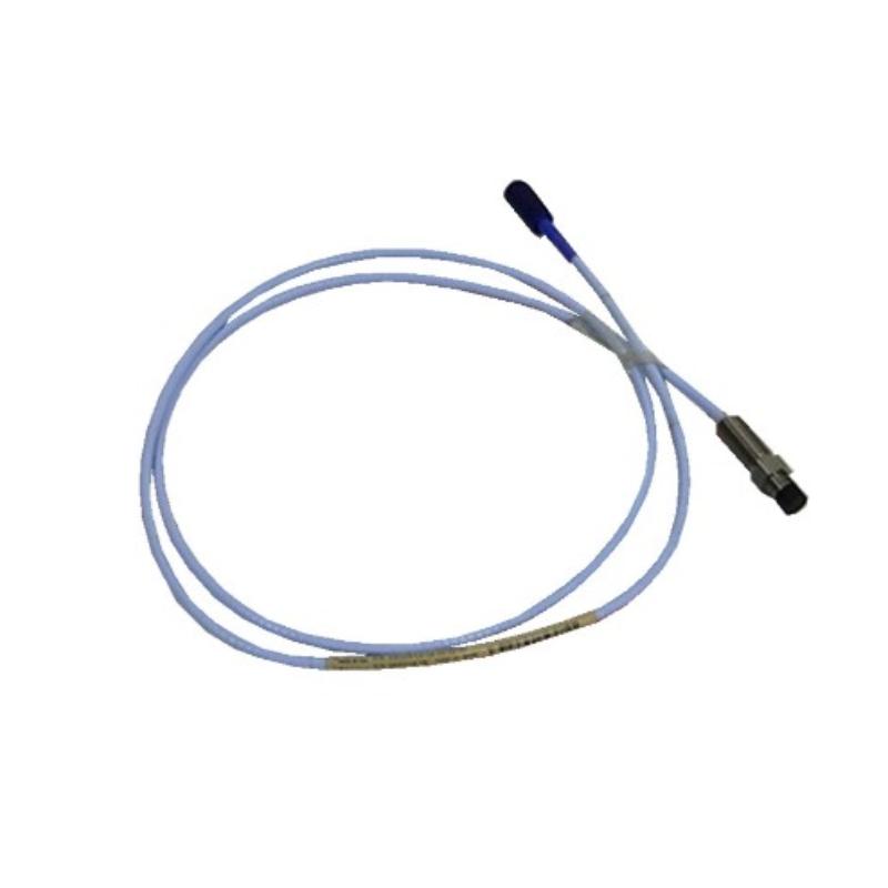
Bently Nevada 330730-080-10-00 Extension Cable: Technical Specifications, Product Description, Applications, Advantages, and Related Models
1. Product Overview
The Bently Nevada 330730-080-10-00 is a model number that requires configuration verification before its detailed specifications can be stated with confidence. It resembles the 3300 XL 11 mm extension-cable model family, but the 10 option is not sufficiently established here to assign a specific cable construction, connector arrangement, or approval status.
The 3300 XL 11 mm extension-cable family is used in proximity transducer systems to connect a compatible probe to a compatible Proximitor sensor. These systems are commonly used to monitor shaft vibration, displacement, and relative position in rotating machinery.
The 080 section is consistent with an 8.0 m nominal cable-length code. However, the complete part number—including the 10-00 suffix—should be checked against the applicable product specification before the item is purchased or installed.
2. Product Parameters
| Parameter | Specification |
|---|---|
| Model | 330730-080-10-00 |
| Brand | Bently Nevada |
| Potential product family | 3300 XL 11 mm proximity transducer system |
| Product type | Extension cable; exact configuration to be confirmed |
| Nominal cable length | 8.0 m, subject to confirmation against the ordering specification |
| Equivalent length | Approximately 26.2 ft |
| Cable construction | Not confirmed for the 10 option |
| Armor | Not confirmed |
| Connector protection | Not confirmed |
| Connector type | Confirm against the exact configuration |
| Approval option | 00 appears in the suffix; exact ordering-code interpretation should be verified |
| Primary function | Connects a compatible proximity probe to a compatible Proximitor sensor, if confirmed as the corresponding extension-cable configuration |
| Typical measurement applications | Shaft vibration, displacement, and relative-position monitoring |
| Cable impedance | Not confirmed for this exact model |
| Capacitance | Not confirmed for this exact model |
| Insulation material | Not confirmed for this exact model |
| Operating temperature | Requires the applicable product specification |
| Cable length dimension | Approximately 8.0 m, if the 080 code is confirmed |
| Cable diameter | Not confirmed |
| Connector dimensions | Not confirmed |
| Overall assembly dimensions | Require the product drawing |
| Net weight | Not confirmed for this exact configuration |
| Weight unit | kg |
| Package dimensions | Not confirmed |
| Gross shipping weight | Not confirmed |
| Installation environment | Industrial machinery instrumentation, subject to the actual cable specification |
| Compatibility | Must be confirmed against the probe, sensor, and complete system configuration |
Important note on dimensions and weight: The nominal cable length is not the same as the overall dimensions of a packaged assembly. The exact cable diameter, connector dimensions, and net weight in kilograms cannot be stated reliably without confirming what the 10 suffix represents. These values should not be inferred from other 330730 cable configurations.
3. Product Introduction
An extension cable in the 3300 XL 11 mm proximity transducer family serves as the electrical link between the sensing probe and the associated Proximitor sensor. The probe is positioned close to a conductive target, such as a rotating shaft, and responds to changes in the gap between the probe tip and the target surface.
The resulting signal travels through the cable to the sensor. The compatible monitoring equipment can then use the measurement to assess shaft vibration, displacement, or other relevant machinery conditions.
Cable selection is important because the extension cable is part of a defined measurement system. Its electrical characteristics, length, connectors, and construction must match the requirements of the probe and sensor. A cable that looks similar or has the same nominal length is not automatically an acceptable substitute.
For the 330730-080-10-00 specifically, the most important preliminary step is confirming the meaning of the 10 configuration code. Until that code is verified, it would be misleading to describe the cable as armored, connector-protected, or certified for a particular installation.
4. Product Applications
4.1 Shaft vibration monitoring
Compatible proximity transducer systems are used to monitor changes in shaft position relative to the probe. The measurement can help maintenance teams identify changes in rotating-machine behaviour and investigate possible mechanical issues.
The extension cable provides the required connection between the probe and sensor. It does not perform vibration analysis on its own.
4.2 Shaft displacement and position measurement
In a suitable installation, a proximity system can monitor changes in the distance between a probe and the shaft. This information may be used to assess relative shaft position and movement.
The cable must be compatible with the measurement system’s electrical and mechanical requirements for the readings to be meaningful.
4.3 Turbines and generators
Turbines and generators often use permanently installed instrumentation to monitor critical rotating components. A compatible extension cable can connect probes installed near designated measurement points to sensors mounted at suitable locations.
The appropriate cable length and construction depend on the actual machine layout and the system configuration.
4.4 Pumps and compressors
Industrial pumps and compressors may use proximity measurement systems as part of their condition-monitoring arrangements. A suitable extension cable helps maintain the connection between the sensing point and the associated electronics.
The cable’s environmental limits and mechanical protection must be appropriate for the installation.
4.5 Industrial maintenance and replacement
The model may be relevant to a maintenance project involving an existing 3300 XL 11 mm system, provided that its exact configuration is confirmed. Before ordering a replacement, compare the full part number, cable length, connector arrangement, and the requirements of the connected probe and sensor.
5. Product Advantages
| Potential advantage | Description | Practical value |
|---|---|---|
| Defined nominal cable length | The 080 code is consistent with an 8.0 m option |
May provide flexibility when the probe and sensor are installed at different locations |
| Dedicated instrumentation use | The 3300 XL family is designed for proximity measurement applications | Supports the signal connection in a compatible system |
| System-based configuration | Cable selection is tied to the probe and sensor arrangement | Helps avoid unsuitable substitutions when the correct configuration is selected |
| Industrial monitoring application | Supports measurement chains used in rotating machinery monitoring | Useful for maintenance and condition-monitoring installations |
| Identifiable ordering code | The complete model number distinguishes the requested configuration | Helps purchasing teams check replacement compatibility |
The advantages of the exact 10 configuration cannot be fully described until its cable construction and option definitions are verified. In particular, mechanical protection, connector protection, and approval status should not be assumed from the model number alone.
6. Brand and Product Series
| Item | Description |
|---|---|
| Brand | Bently Nevada |
| Potential series | 3300 XL |
| Related system | 3300 XL 11 mm proximity transducer system |
| Potential component category | Extension cable |
| Typical system function | Signal connection between a compatible proximity probe and Proximitor sensor |
| Typical measurements | Shaft vibration, displacement, and relative position |
| Common application areas | Power generation, oil and gas, petrochemical processing, and heavy industry |
The 3300 XL 11 mm system comprises multiple components, including probes, extension cables, and Proximitor sensors. These components work together as a measurement chain, so the exact cable configuration matters to the overall installation.
The model number presented here should be confirmed against the actual product label or the applicable configuration record before it is treated as a fully identified extension cable.
7. Five Related Models for Comparison
The following are comparison candidates from the same general extension-cable family or related system. They are not confirmed direct replacements for the 10 configuration.
| Model | Product type | Nominal length | Configuration | Dimensions | Weight |
|---|---|---|---|---|---|
| 330730-080-00-00 | Extension cable | 8.0 m, subject to code confirmation | Standard configuration candidate | Cable length approximately 8.0 m; diameter unconfirmed | Net weight unconfirmed |
| 330730-080-01-00 | Extension cable | 8.0 m, subject to code confirmation | Armored configuration candidate | Cable length approximately 8.0 m; diameter unconfirmed | Net weight unconfirmed |
| 330730-080-02-00 | Extension cable | 8.0 m, subject to code confirmation | Connector-protected configuration candidate | Cable length approximately 8.0 m; diameter unconfirmed | Net weight unconfirmed |
| 330730-080-03-00 | Extension cable | 8.0 m, subject to code confirmation | Armored cable with connector protectors in the corresponding option scheme | Cable length approximately 8.0 m; diameter unconfirmed | Net weight unconfirmed |
| 330730-040-03-00 | Extension cable | 4.0 m, subject to code confirmation | Armored and connector-protected configuration candidate | Cable length approximately 4.0 m; diameter unconfirmed | Net weight unconfirmed |
These examples illustrate possible differences in cable length and construction within the broader model family. Their option definitions and availability must be checked against the actual ordering specification. The 10 suffix on the target model should not be assumed to mean the same thing as any of these options.
8. Five Other Models for Machinery-Monitoring Comparison
These examples cover other component types used in machinery monitoring. They are not direct substitutes for an extension cable, and the complete part numbers must be checked before procurement.
| Model | Product type | Main function | Typical application | Dimensions | Weight |
|---|---|---|---|---|---|
| 330101-00-08-10-02-00 | Proximity probe model candidate | Non-contact proximity measurement | Shaft vibration and displacement monitoring | Depends on exact probe configuration; drawing required | Exact weight unconfirmed |
| 330103-00-08-10-02-00 | Proximity probe model candidate | Non-contact proximity measurement | Rotating-machinery monitoring | Depends on exact probe configuration; drawing required | Exact weight unconfirmed |
| 330104-00-08-10-02-00 | Proximity probe model candidate | Non-contact proximity measurement | Machinery condition monitoring | Depends on exact probe configuration; drawing required | Exact weight unconfirmed |
| 330180-50-00 | Proximitor sensor model candidate | Interfaces compatible probes and extension cables with monitoring equipment | Shaft vibration and displacement measurement | Depends on exact sensor configuration; drawing required | Exact weight unconfirmed |
| 3500/42M | Proximitor/seismic monitoring module | Receives compatible transducer signals for monitoring | Machinery vibration and position monitoring | Rack-module dimensions; verify applicable configuration | Exact weight unconfirmed |
The probe models are examples for comparison, not confirmation that each listed suffix is appropriate for a particular installation. The sensor and monitoring-module models perform different functions from the extension cable and cannot replace it directly.
9. Installation and Maintenance Considerations
Before installation, inspect the cable for visible damage, connector deformation, or contamination. Confirm that the connectors and cable construction match the installation requirements.
Route the cable to avoid pinching, excessive bending, sharp edges, and unnecessary mechanical stress. If the confirmed configuration includes armor, use it as additional protection rather than as a substitute for correct routing and cable support.
During replacement, record the complete existing part number and compare it with the proposed replacement. Confirm the 10 option’s meaning before ordering, and check compatibility with the probe and Proximitor sensor.
After installation, verify the connections and confirm that the complete measurement system produces expected readings. An abnormal signal may result from the probe, cable, connectors, sensor, or monitoring equipment, so troubleshooting should consider the entire measurement chain.
10. Procurement Checklist
| Checkpoint | Required action |
|---|---|
| Complete part number | Confirm 330730-080-10-00 from the product label |
080 length option |
Verify that 8.0 m is the correct nominal length |
10 configuration |
Obtain the exact definition before specifying cable construction |
00 option |
Confirm its meaning in the applicable ordering scheme |
| Connector arrangement | Check the required connector type and dimensions |
| Probe compatibility | Confirm the exact probe model |
| Sensor compatibility | Confirm the Proximitor sensor and complete system configuration |
| Cable dimensions | Obtain the physical drawing |
| Net weight | Confirm the actual assembly weight in kg |
| Environmental requirements | Check temperature, moisture, chemical exposure, and routing conditions |
11. Final Summary
The Bently Nevada 330730-080-10-00 appears consistent with the model-number pattern used for 3300 XL 11 mm extension-cable configurations, with 080 indicating a nominal 8.0 m length. However, the meaning of the 10 suffix and the exact construction of this configuration are not sufficiently established to provide a definitive specification.
The cable’s potential role is to connect a compatible proximity probe to a compatible Proximitor sensor for shaft vibration and displacement monitoring. Before selecting it, verify the full part number, cable construction, connector arrangement, electrical characteristics, and system compatibility.
The exact cable diameter, overall assembly dimensions, and net weight in kilograms should also be obtained from the applicable product specification. This avoids using estimated or unrelated values in purchasing records, engineering documentation, or installation planning.