

ProductPRODUCT
Featured products
Contact Us
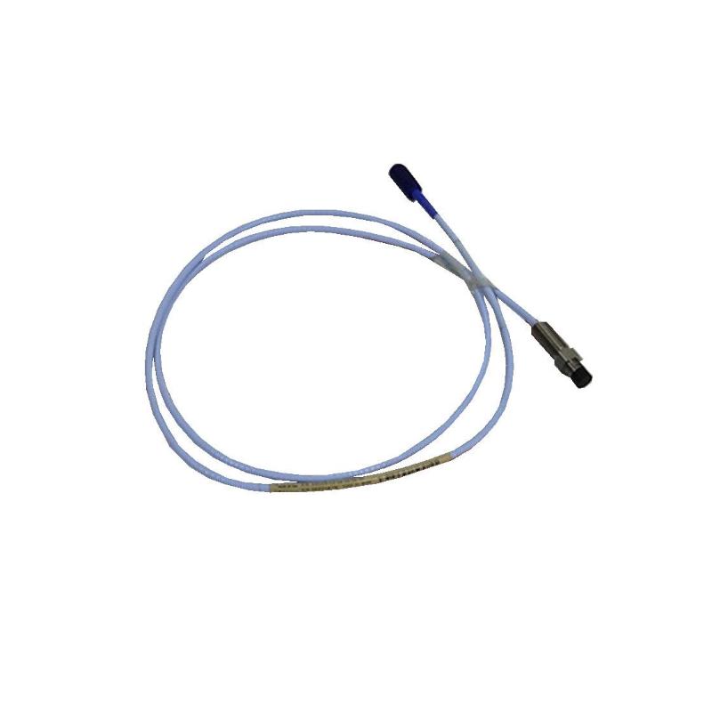
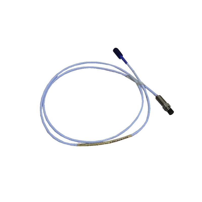
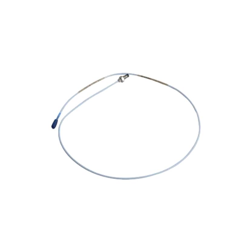
- Bently Nevada
- 330730-080-02-05
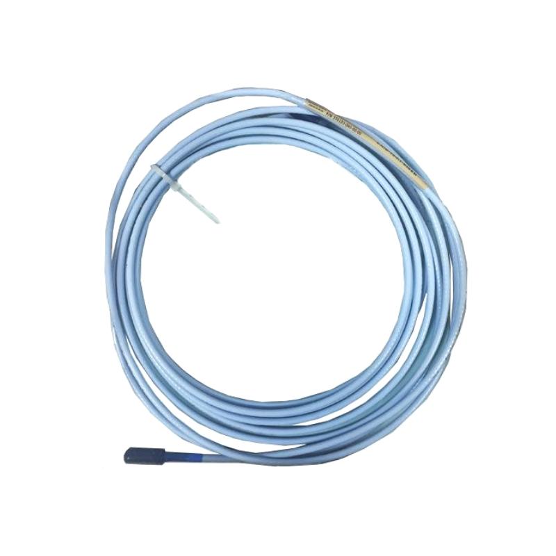
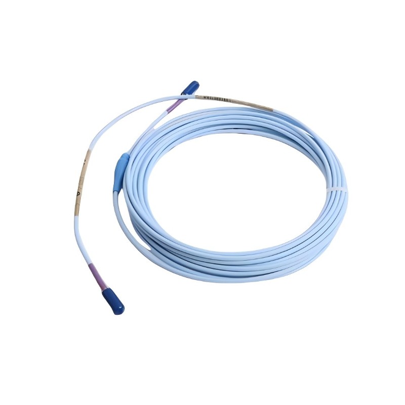
- 3300 XL 11mm Extension Cable
- USA
- 8.0 m
- 0.36kg
- Xiamen, China
- New & In Stock
- T/T, PayPal, Western Union
- 1 Year
- 1-3 Working Days
- DHL, UPS, TNT, FedEx and EMS.
- 24-Hour Service
- COO
- 5
Our advantage

Global Logistics
We have a 10-year logistics and express cooperation agreement, so our products can be shipped to any place in the world.

Brand new and original
Our products are imported in bulk from the place of origin. Because of the cooperative relationship, our products are all original and 100% new.

24-hour service
We provide 7*24 hours service to our customers. We will be there whenever you need us.

Price advantage
All our products are priced very favorably because we have our own warehouse and supply.
| Company Information | |||
| [email protected] | |||
| Mobile | +8615980777398 | ||
| +8615980777398 | |||
| 15980777398 |
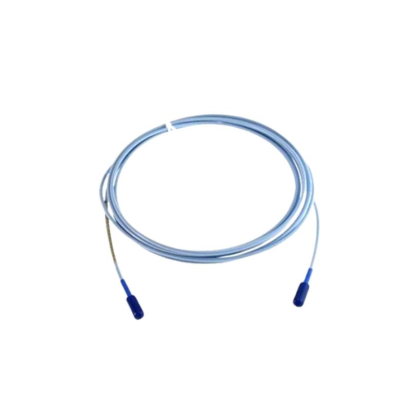
Bently Nevada 330730-080-02-05 Extension Cable — Technical Specifications, Product Description, Applications, Advantages, and Related Models
1. Product Overview
The Bently Nevada 330730-080-02-05 is a model designation associated with the 3300 XL 11 mm proximity measurement system extension cable family. This type of extension cable connects a compatible proximity probe to its associated Proximitor sensor and forms part of the electrical measurement circuit used in industrial machinery monitoring.
In rotating machinery installations, proximity measurement systems are commonly used to monitor shaft vibration and relative shaft position. When the probe, extension cable, sensor, and monitoring equipment are correctly matched, the complete system can provide information that helps maintenance teams assess machine condition and investigate abnormal operating behavior.
Typical applications include steam turbines, gas turbines, centrifugal compressors, pumps, electric motors, and other rotating equipment used in continuous industrial processes.
The extension cable is not an independent measuring instrument. Its role is to provide a suitable electrical connection between compatible system components. Cable length, electrical characteristics, connector configuration, and physical construction must therefore match the requirements of the installed measurement system.
The full suffix “-02-05” should be checked against the applicable ordering specification. Similar model numbers may differ in cable construction, connector protection, and approval options, so those details should not be assumed solely from a partial model number.
2. Brand and Product Series
| Parameter | Description |
|---|---|
| Model | 330730-080-02-05 |
| Brand | Bently Nevada |
| Product series | 3300 XL 11 mm proximity measurement system |
| Product category | Extension cable |
| Main function | Connects a compatible proximity probe to its associated sensor interface |
| Measurement application | Shaft vibration and relative shaft displacement monitoring |
| Typical equipment | Turbines, compressors, pumps, motors, and other rotating machinery |
| Nominal cable length | The “080” code is commonly associated with an 8.0 m configuration in this model family; confirm the complete ordering code |
| Cable construction | Industrial instrumentation cable; verify the exact assembly |
| Connector configuration | Must be confirmed against the complete part number |
| Approval option | The “05” suffix is associated with an approval option in this product family; confirm the precise approvals for the supplied unit |
| Replacement compatibility | Depends on cable length, electrical characteristics, connector arrangement, and system requirements |
3. Detailed Technical Specifications
The 330730-080-02-05 is an 8.0 m extension cable with a standard cable configuration and connector protector. The “05” ordering option is associated with multiple agency approvals, while the “02” option identifies the standard cable with connector protector.
| Parameter | Technical specification |
|---|---|
| Model | 330730-080-02-05 |
| Brand | Bently Nevada |
| Product series | 3300 XL 11 mm proximity measurement system |
| Product type | Extension cable |
| Cable length | 8.0 m (26.2 ft) |
| Connector and cable option | Standard cable with connector protector |
| Agency approval option | Multiple approvals; verify the certificates applicable to the supplied unit |
| Cable impedance | 75 Ω triaxial construction |
| Insulation material | Fluoroethylene propylene (FEP) |
| Typical capacitance | 69.9 pF/m (21.3 pF/ft) |
| Center-conductor resistance | Approximately 2.0 ± 0.5 Ω for an 8 m assembly in the applicable configuration |
| Coaxial-conductor resistance | Approximately 0.6 ± 0.2 Ω for an 8 m assembly in the applicable configuration |
| Operating temperature | Approximately −51°C to +177°C for the relevant cable family; confirm the exact assembly rating |
| Storage temperature | Confirm the applicable product specification |
| Cable outside diameter | Confirm from the cable assembly drawing |
| Connector dimensions | Depend on the connector arrangement and protective cover |
| Overall cable length | 8.0 m nominal |
| Listed package dimensions | Approximately 20.4 × 22.2 × 3.7 cm in one listing; packaging dimensions may vary |
| Net weight | Approximately 0.36 kg in several listings |
| Weight (kg) | Approximately 0.36 kg, subject to confirmation of the supplied assembly |
| Shipping weight | Varies with packaging and shipping configuration |
| Cable protection | Standard cable with connector protector |
| Armor | Not implied by the “02” option; confirm separately if full-length armor is required |
| Main function | Electrical connection between compatible proximity system components |
| Installation type | Industrial machinery instrumentation |
The listed package dimensions refer to the packaged product, not the full 8 m cable laid out. The net weight is an approximate listing value, so the actual assembly specification should be used for engineering calculations and shipping records.
4. Product Description
4.1 Purpose and operating principle
The 330730-080-02-05 is designed to extend the electrical connection between a compatible proximity probe and its associated Proximitor sensor. It is part of the 3300 XL 11 mm proximity measurement system, which is used for non-contact shaft vibration and displacement measurements.
A proximity probe detects changes in the distance between its sensing face and a conductive target, usually a rotating shaft. The associated sensor processes the electrical response, and the monitoring system uses the resulting signal to assess shaft movement and machinery condition.
The extension cable forms an important part of this measurement chain. Its electrical characteristics must match the connected components so that the complete system operates as intended.
4.2 Cable construction and connector protection
The cable uses a triaxial construction with FEP insulation. Its specified capacitance is important for maintaining the electrical characteristics of the compatible transducer system.
The “02” configuration includes a standard cable with a connector protector. This protector helps shield the connector area from incidental contact and environmental exposure when correctly installed.
Connector protection and full-length cable armor are different features. If the installation requires stainless-steel armor along the cable route, that requirement should be checked against the exact part number and assembly drawing.
4.3 Electrical signal transmission
The typical cable capacitance of 69.9 pF/m is a key electrical parameter. Cable length and capacitance contribute to the behavior of the complete probe-and-sensor circuit.
Using an incompatible cable may affect measurement performance or system calibration. A replacement should therefore be selected according to the complete model number and electrical requirements, rather than physical appearance alone.
4.4 Multiple approval configuration
The “05” ordering option is associated with multiple agency approvals in this product family. The exact approvals and certificate applicability should be verified for the supplied assembly and intended installation.
This is particularly important where equipment is installed in a regulated or hazardous area. The suffix alone should not be treated as proof that every approval applies to every installation.
4.5 Industrial operating suitability
The cable is intended for use in compatible industrial machinery monitoring installations. Its connector protector offers additional protection at the connection point, while the cable’s electrical characteristics support signal transmission.
The complete installation must still comply with the actual cable temperature rating, environmental requirements, routing restrictions, and system compatibility requirements.
5. Product Applications
5.1 Steam turbines
Steam turbines are often equipped with proximity measurement systems to monitor shaft vibration and relative shaft position. These measurements can help maintenance personnel investigate changes in operating behavior and assess machine condition.
The extension cable provides the electrical connection between the probe and sensor electronics. Maintaining the correct cable configuration helps the monitoring system receive the intended measurement signal.
5.2 Gas turbines
Gas turbines operate at high speeds and under demanding mechanical and thermal conditions. A compatible extension cable supports the measurement system used to monitor shaft behavior.
The connector protector helps protect the connection area, but it does not replace full-length armor where additional mechanical protection is required.
5.3 Centrifugal compressors
Centrifugal compressors are used in continuous industrial processes, where unexpected equipment downtime can be costly. Proximity measurements can help engineers monitor shaft vibration and investigate unusual operating conditions.
A correctly installed extension cable helps maintain the electrical connection between the probe and the sensor. Damaged connectors or an incompatible cable configuration may affect the reliability of the measurement channel.
5.4 Pumps and electric motors
Large pumps and motors may use proximity measurement systems for shaft movement monitoring. The extension cable connects the sensing component to its associated electronics.
During maintenance, the cable and its connectors should be checked alongside the probe and sensor. This helps distinguish cable faults from other possible causes of abnormal readings.
5.5 Process-industry machinery
The cable may be used in compatible rotating machinery installations in refining, chemical processing, manufacturing, and other process industries.
Suitability depends on the installed proximity measurement system and the actual environmental conditions. Hazardous-area installations require verification of the relevant approval documentation.
5.6 Equipment maintenance and refurbishment
The model may be used when replacing a damaged cable in an existing compatible 3300 XL 11 mm installation. Matching the original model helps preserve the intended electrical configuration and reduces the likelihood of ordering an unsuitable replacement.
Before ordering, confirm the cable length, connector protector, electrical characteristics, approval requirements, and any need for full-length armor.
6. Product Advantages
6.1 Defined electrical characteristics
The specified 75 Ω triaxial construction and typical capacitance help maintain the electrical characteristics required by the compatible proximity measurement system.
Using the correct cable helps avoid issues associated with incorrect electrical length or an incompatible cable type.
6.2 Connector protection
The standard connector-protector configuration helps shield the connector area from incidental contact and certain environmental exposures.
This is useful where the connection point needs additional protection, although it does not eliminate the need for proper installation and inspection.
6.3 Practical 8 m cable length
The nominal 8.0 m length offers flexibility when the probe and sensor are separated by a significant distance within the machinery installation.
The length must still be appropriate for the electrical configuration of the complete transducer system.
6.4 Support for approved installations
The “05” option is associated with multiple agency approvals in this model family. Where approvals are required, the corresponding documentation can help determine whether the supplied configuration is suitable for the intended location.
The actual certificate and its scope should always be checked before installation.
6.5 Replaceable component
An extension cable can be inspected and replaced independently of the probe, sensor, and monitoring equipment. This can simplify troubleshooting when damage or connection problems are identified.
A structured diagnostic process should still consider other possible causes, including probe condition, sensor configuration, grounding, and monitor-channel faults.
6.6 Easier spare-parts planning
Recording the complete part number helps maintenance teams distinguish between cable lengths, connector options, and approval configurations.
For critical machinery, maintaining accurate spare-parts records can reduce ordering mistakes and avoid unnecessary delays during repairs.
7. Installation and Maintenance Recommendations
Before installation
-
Verify the complete model number: 330730-080-02-05.
-
Confirm that the required cable length is 8.0 m.
-
Check that the standard connector-protector configuration matches the installation requirement.
-
Verify electrical compatibility with the installed probe and Proximitor sensor.
-
Confirm the approvals required for the installation.
-
Determine whether full-length cable armor is necessary.
-
Inspect the cable and connectors for visible damage.
During installation
-
Route the cable away from sharp edges and moving machinery.
-
Observe the minimum bend radius specified for the actual assembly.
-
Avoid pulling the cable by its connector.
-
Secure the cable without crushing or deforming the jacket.
-
Keep connectors clean and fully engaged.
-
Follow the approved installation procedure for the complete measurement system.
During maintenance
-
Inspect the cable and connector protector for abrasion, cracking, or other damage.
-
Check the connector for contamination, looseness, and physical deterioration.
-
Investigate abnormal readings by checking the complete measurement channel.
-
Replace damaged cables with electrically compatible assemblies.
-
Record the installed model and replacement details in the maintenance history.
8. Five Related Models in the Same Series
The following models are candidates for comparison within the same extension cable family. Their exact ordering options and specifications should be checked before selecting a replacement.
| Model | Product description | Main parameters | Dimensions | Weight (kg) |
|---|---|---|---|---|
| 330730-080-02-00 | 3300 XL 11 mm extension cable with connector protector | 8.0 m nominal length; approval not required under the “00” option | 8.0 m cable length; package dimensions depend on packaging | Approximately 0.36 kg listed; verify the supplied unit |
| 330730-080-02-CN | 3300 XL 11 mm extension cable with connector protector | 8.0 m nominal length; country-specific approval configuration | 8.0 m nominal length; exact connector dimensions require drawing confirmation | Not confirmed for the exact configuration |
| 330730-080-02-RU | 3300 XL 11 mm extension cable with connector protector | 8.0 m nominal length; verify the approval option | 8.0 m nominal length; connector dimensions require confirmation | Not confirmed for the exact configuration |
| 330730-040-02-05 | Shorter extension cable in the same family | 4.0 m nominal configuration; multiple approvals associated with “05” | 4.0 m nominal cable length; exact assembly dimensions require confirmation | Not confirmed |
| 330730-120-02-05 | Longer extension cable in the same family | 12.0 m configuration candidate; verify the exact ordering code and availability | Confirm actual cable length and assembly drawing | Not confirmed |
These models are not automatically interchangeable. Cable length, connector configuration, electrical characteristics, and approval requirements must match the installed system.
9. Five Additional Models from the Same Brand
The following products represent other components used in machinery condition monitoring. They have different functions and should not be treated as direct replacements for an extension cable.
| Model | Product category | Main function | Dimensions | Weight (kg) |
|---|---|---|---|---|
| 330101-00-08-10-02-00 | 3300 XL 8 mm proximity probe configuration | Non-contact shaft displacement and vibration measurement | Depends on probe length, thread, and mounting configuration | Not confirmed for the exact configuration |
| 330103-00-07-10-02-00 | 3300 XL 8 mm proximity probe configuration | Provides proximity measurement signals in a compatible system | Depends on the complete probe configuration | Not confirmed for the exact configuration |
| 330104-00-06-10-02-00 | 3300 XL 8 mm proximity probe configuration | Supports shaft movement monitoring | Depends on probe length and mounting arrangement | Not confirmed for the exact configuration |
| 330180-50-00 | 3300 XL proximity probe family; verify the exact configuration | Non-contact displacement measurement | Confirm from the specific product drawing | Not confirmed |
| 3500/42M | Machinery monitoring module | Supports vibration and position monitoring with compatible transducer inputs | Depends on module hardware and rack configuration | Not confirmed for the exact configuration |
The complete model code should be confirmed before purchasing. Probe dimensions, thread types, connectors, and system compatibility can vary by configuration.
10. Comparison of the Main Model and Related Cable Options
| Comparison item | 330730-080-02-05 | 330730-080-02-00 | 330730-080-02-CN | 330730-040-02-05 |
|---|---|---|---|---|
| Product family | 3300 XL 11 mm | 3300 XL 11 mm | 3300 XL 11 mm | 3300 XL 11 mm |
| Component type | Extension cable | Extension cable | Extension cable | Extension cable |
| Nominal length | 8.0 m | 8.0 m | 8.0 m | 4.0 m |
| Connector configuration | Standard cable with connector protector | Standard cable with connector protector | Standard cable with connector protector | Verify exact configuration |
| Approval option | Multiple approvals | Not required | Country-specific option | Multiple approvals |
| Typical capacitance | 69.9 pF/m | 69.9 pF/m for the applicable configuration | 69.9 pF/m for the applicable configuration | Confirm exact specification |
| Dimensions | 8.0 m cable; package listing around 20.4 × 22.2 × 3.7 cm | 8.0 m cable; packaging varies | 8.0 m cable; packaging varies | 4.0 m nominal; drawing required |
| Net weight (kg) | Approximately 0.36 kg | Approximately 0.36 kg listed; verify | Not confirmed | Not confirmed |
| Direct replacement suitability | Reference model | Check approval requirements | Check approval requirements | Only if the shorter cable meets system requirements |
11. Purchasing Checklist
Before purchasing the 330730-080-02-05, confirm the following:
1. Complete model number: Match the full ordering code, including the final approval suffix.
2. Cable length: Confirm that 8.0 m is the required length.
3. Connector protector: Ensure the standard connector-protector configuration is suitable for the installation.
4. Electrical compatibility: Verify compatibility with the installed probe and Proximitor sensor.
5. Approval requirements: Confirm which agency approvals are required and whether the supplied unit meets those requirements.
6. Armor requirements: Check whether the installation requires full-length cable armor.
7. Dimensions: Use the assembly drawing for cable diameter, connector dimensions, and routing clearance.
8. Net weight: Use the verified assembly weight for equipment records and the packaged weight for transport calculations.
9. Product condition: Inspect the cable, connectors, and protective components before installation.
10. Commissioning: After replacement, verify the measurement channel according to the approved site procedure.
12. Conclusion
The Bently Nevada 330730-080-02-05 is an 8.0 m extension cable for the 3300 XL 11 mm proximity measurement system. Its standard cable and connector-protector configuration provides the connection required between compatible proximity probes and their associated sensor electronics.
Its main advantages are the defined electrical characteristics, practical cable length, connector protection, and availability of an approval configuration intended for installations requiring multiple agency approvals.
For procurement and maintenance, the most important checks are the full model number, cable length, connector configuration, electrical compatibility, approval requirements, and whether full-length armor is needed.
The listed net weight is approximately 0.36 kg, while package dimensions and shipping weight may vary. For formal engineering documents or replacement orders, use the exact assembly drawing and product specification to confirm the dimensions, weight, and approvals of the supplied unit.