

ProductPRODUCT
Featured products
Contact Us
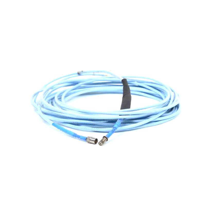
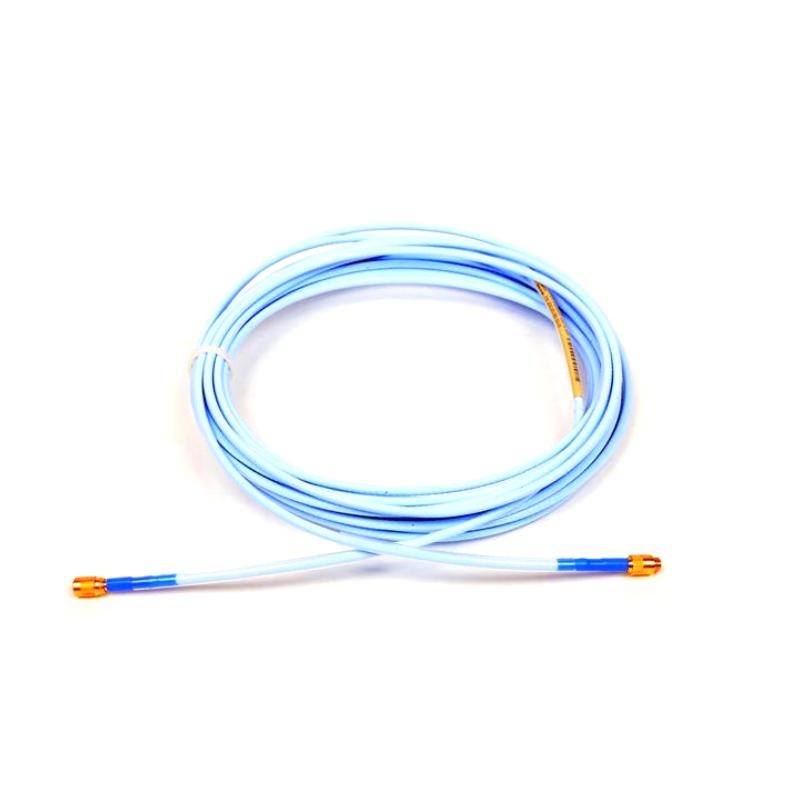
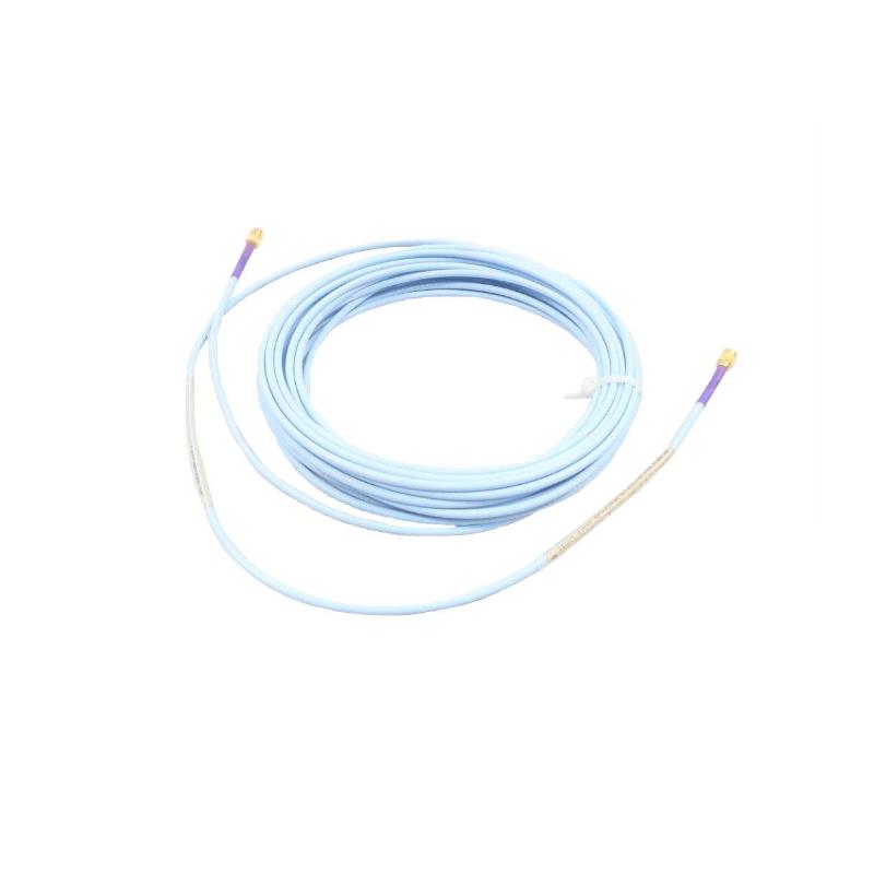
- Bently Nevada
- 330730-080-01-05
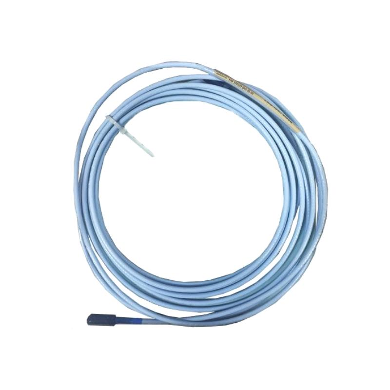
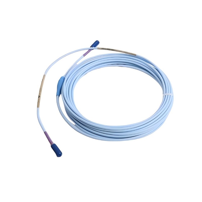
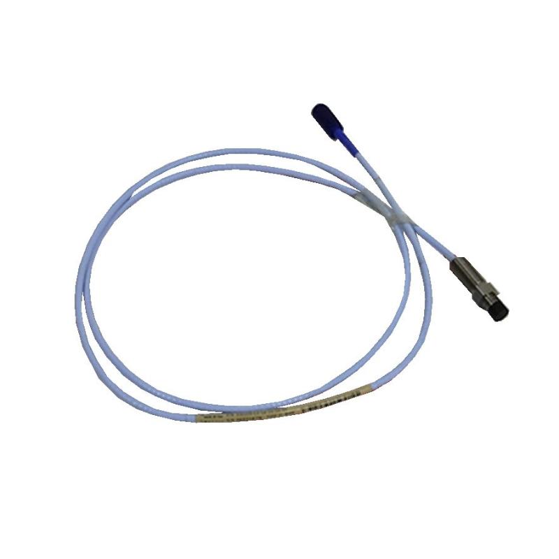
- 3300 XL 11mm Extension Cable
- USA
- 8.0 m
- 1kg
- Xiamen, China
- New & In Stock
- T/T, PayPal, Western Union
- 1 Year
- 1-3 Working Days
- DHL, UPS, TNT, FedEx and EMS.
- 24-Hour Service
- COO
- 4
Our advantage

Global Logistics
We have a 10-year logistics and express cooperation agreement, so our products can be shipped to any place in the world.

Brand new and original
Our products are imported in bulk from the place of origin. Because of the cooperative relationship, our products are all original and 100% new.

24-hour service
We provide 7*24 hours service to our customers. We will be there whenever you need us.

Price advantage
All our products are priced very favorably because we have our own warehouse and supply.
| Company Information | |||
| [email protected] | |||
| Mobile | +8615980777398 | ||
| +8615980777398 | |||
| 15980777398 |
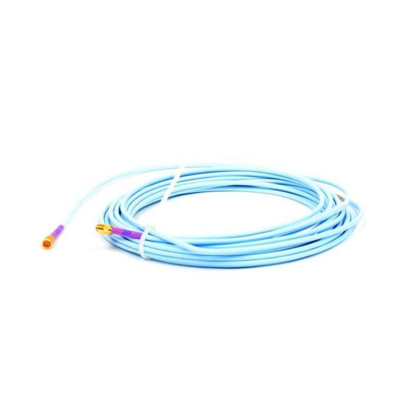
Bently Nevada 330730-080-01-05 Extension Cable — Product Description, Technical Parameters, Applications, and Related Models
1. Product Overview
The Bently Nevada 330730-080-01-05 is a model designation associated with the 3300 XL 11 mm proximity measurement system’s extension cable family. This type of cable is used to connect compatible proximity probes to their corresponding sensor interface components, helping transmit measurement signals used for machinery condition monitoring.
In a typical installation, the extension cable forms part of a non-contact displacement measurement chain. When paired with compatible components, the system can measure shaft vibration and relative shaft position in rotating machinery. These measurements help maintenance teams assess machine condition, identify abnormal operating behavior, and plan inspections before minor issues develop into serious failures.
The exact configuration should be confirmed against the equipment nameplate and system bill of materials. In particular, the suffix “-05” should not be interpreted as a specific certification, connector, or cable-length option without the applicable ordering-code documentation.
2. Technical Parameters
The following table summarizes the product family and the key installation parameters. Values that depend on the exact ordering configuration are marked for confirmation rather than presented as guaranteed specifications.
| Parameter | Description |
|---|---|
| Model | 330730-080-01-05 |
| Brand | Bently Nevada |
| Product series | 3300 XL 11 mm proximity measurement system |
| Product type | Extension cable |
| Primary function | Connects a compatible proximity probe to the associated sensor interface |
| Measurement principle | Non-contact proximity measurement when used in a compatible system |
| Typical application | Shaft vibration and relative shaft displacement monitoring |
| Nominal cable length | The “080” code is commonly associated with an 8.0 m configuration in this model family; confirm the exact ordering code before installation |
| Cable construction | Designed for industrial machinery instrumentation; exact construction should be checked against the supplied assembly |
| Connector configuration | Must be confirmed against the full model code and installed system |
| Electrical compatibility | Must match the associated probe and sensor interface |
| Operating temperature | Confirm the permitted range for the exact cable assembly and installation environment |
| Overall dimensions | Cable length and diameter depend on the specified configuration; do not treat the model number alone as confirmation of every dimension |
| Approximate cable diameter | A nominal diameter around 11 mm may be associated with this product family, but the exact cable outside diameter requires confirmation |
| Net weight | Not confirmed for this exact suffix |
| Weight in kg | Calculate from the verified assembly weight or supplier packing specification; do not substitute shipping weight for net product weight |
| Installation environment | Industrial machinery installations, subject to the cable’s actual environmental and mechanical ratings |
| Mounting method | Routed between compatible sensor components, with connectors secured according to installation instructions |
| Maintenance requirement | Inspect connectors, cable routing, protective covering, and signs of mechanical damage during scheduled maintenance |
Important specification note: The model number alone is not enough to guarantee the precise dimensions, net weight, temperature rating, connector arrangement, or approval status of the complete assembly. These details should be checked against the actual product label or the equipment documentation before purchasing a replacement or preparing an engineering specification.
3. Detailed Product Description
The 330730-080-01-05 is an armored extension cable intended for use in compatible 3300 XL 11 mm proximity transducer installations. Its main purpose is to provide an electrical connection between the proximity probe and the associated Proximitor sensor while preserving the signal characteristics required for accurate displacement measurement.
The cable is intended for industrial environments where rotating machinery operates continuously and measurement reliability is important. Typical installations include turbine systems, compressors, pumps, motors, and other large rotating machines whose shaft movement needs to be monitored.
Cable construction and materials
The cable uses a 75 Ω triaxial design with fluoroethylene propylene (FEP) insulation. The armored configuration incorporates flexible AISI 302 stainless-steel protection with an FEP outer jacket. This construction helps protect the cable against mechanical contact and damage during routing and operation.
The stainless-steel armor is particularly useful where the cable passes near machinery structures, equipment brackets, or other areas where an unprotected cable may be vulnerable to abrasion. The outer jacket provides an additional protective layer around the cable assembly.
Electrical signal transmission
An extension cable is not simply a length of ordinary wiring. In a proximity transducer system, its electrical characteristics form part of the measurement circuit. Cable capacitance, impedance, total electrical length, connector condition, and compatibility with the probe and Proximitor sensor can all affect system performance.
For this reason, the extension cable should be selected as part of the complete measurement chain rather than as an isolated component. A cable with the correct physical length but an incompatible electrical configuration may not provide the expected measurement accuracy.
Connector design
The 3300 XL family uses ClickLoc-style connections on compatible components. These connections are designed to provide a secure mating interface and help reduce the risk of accidental loosening under machinery vibration.
During installation, both connectors should be inspected for contamination, damage, corrosion, and signs of improper engagement. The cable should not be sharply bent or placed under excessive tension close to the connector ends.
4. Detailed Technical Specifications
| Technical item | Specification or description |
|---|---|
| Model | 330730-080-01-05 |
| Brand | Bently Nevada |
| Series | 3300 XL 11 mm |
| Component category | Extension cable |
| Cable length | 8.0 m (26.2 ft) |
| Cable configuration | Armored |
| Nominal impedance | 75 Ω |
| Cable type | Triaxial |
| Insulation | FEP |
| Armor material | Flexible AISI 302 stainless steel |
| Outer jacket | FEP |
| Typical capacitance | 69.9 pF/m (21.3 pF/ft) |
| Center-conductor resistance, 8 m assembly | 2.0 ± 0.5 Ω |
| Coaxial-conductor resistance, 8 m assembly | 0.6 ± 0.2 Ω |
| Operating and storage temperature | Approximately −51°C to +177°C |
| Connector family | ClickLoc-style, subject to exact assembly configuration |
| Agency approval option | The “-05” suffix is associated with a multiple-approval configuration in this product family; confirm the applicable approvals for the supplied unit |
| Cable outside diameter | Confirm from the product drawing; do not assume the “11 mm” system designation is the exact cable diameter |
| Overall physical length | Nominal cable length 8.0 m; end-to-end assembly dimensions should be checked against the drawing |
| Net weight | Published listings are inconsistent |
| Approximate listed weight | Some listings show approximately 0.36–0.80 kg for the product; confirm actual net weight |
| Armor-based mass estimate | At 140 g/m, an 8 m cable would weigh approximately 1.12 kg before any differences in how the assembly is measured |
| Shipping dimensions | Depend on packaging and connector protection |
| Shipping weight | Must be distinguished from the net weight of the cable |
| Intended function | Signal connection in a compatible proximity measurement system |
| Replacement requirement | Match the complete part number, electrical length, cable construction, connector configuration, and required approvals |
Weight clarification: Available product listings do not agree on the net weight of this exact assembly. For purchasing documents, logistics calculations, or equipment design, use the measured weight or the weight on the actual product datasheet rather than treating a vendor listing or a calculated cable-mass estimate as definitive.
5. Product Applications
5.1 Steam turbines and power-generation equipment
In power-generation facilities, rotating shafts need to be monitored for vibration and relative displacement. The extension cable connects the compatible probe to the associated sensor interface so that shaft movement can be passed to the monitoring system.
When used with a correctly configured transducer system, it supports condition monitoring intended to identify changes in machinery behavior before they develop into more serious operating problems.
5.2 Industrial gas turbines
Gas turbines operate at high rotational speeds and can be exposed to elevated temperatures, mechanical vibration, and demanding installation conditions. The armored cable configuration offers additional physical protection along the cable route.
The cable itself does not measure vibration independently; it supports the measurement chain formed by the probe, extension cable, Proximitor sensor, and monitoring equipment.
5.3 Centrifugal compressors
Centrifugal compressors are widely used in process industries and other continuous-operation facilities. Shaft vibration and relative position measurements can help engineers assess machine stability, identify changing operating conditions, and investigate unusual vibration patterns.
The extension cable provides the electrical link needed for the compatible proximity measurement system to transmit its signal to the associated instrumentation.
5.4 Pumps and electric motors
Large pumps and motors may require continuous monitoring because unexpected mechanical deterioration can lead to downtime or equipment damage. A correctly installed extension cable helps maintain the connection between the sensor and the monitoring electronics.
The armored construction can be useful in installations where the cable is exposed to incidental contact, vibration, or mechanical interference.
5.5 Industrial machinery protection systems
In machinery protection installations, proximity measurements may be used alongside other monitoring inputs to assess machine condition and support protective actions.
The extension cable contributes to the reliability of the measurement path. It should be installed with the correct probe, sensor, and monitor combination so that the complete system operates within its specified electrical and mechanical limits.
5.6 Axial position and thrust monitoring
A compatible proximity transducer system can be used to monitor shaft axial position. Changes in axial position may indicate changes in thrust-bearing behavior, machine loading, or other mechanical conditions.
The cable is a supporting component in this arrangement; the measurement range and accuracy depend on the complete transducer system and its configuration.
5.7 Maintenance and equipment refurbishment
The model can also be relevant when restoring an existing monitoring system, replacing a damaged cable, or maintaining machinery that already uses compatible 3300 XL components.
Before replacing an installed cable, maintenance personnel should verify the original part number, cable length, armor type, approval option, and system electrical length. A cable that appears physically similar is not necessarily an interchangeable replacement.
6. Product Advantages
6.1 Additional mechanical protection
The stainless-steel armor provides an extra protective layer compared with an unarmored cable. This can help reduce damage from abrasion and incidental mechanical contact in demanding installations.
The armor does not make the cable indestructible. Appropriate routing, support, bend radius, and protection from sharp edges remain necessary.
6.2 Suitability for a broad temperature range
The stated operating and storage temperature range of approximately −51°C to +177°C makes the cable family suitable for a variety of demanding industrial environments.
Actual suitability depends on the full assembly, the installation location, connector exposure, and the temperature limits specified for the particular application.
6.3 Defined electrical characteristics
The 75 Ω triaxial construction and specified capacitance help maintain the electrical characteristics required by the compatible proximity measurement system.
Using the correct cable helps avoid problems associated with incorrect electrical length, incompatible cable construction, or unsuitable replacement wiring.
6.4 Secure connection arrangement
Compatible ClickLoc-style connectors are designed to lock into place, helping maintain a stable connection in machinery environments subject to vibration.
Good installation practices are still essential. Connections should be fully engaged and protected from contamination and environmental exposure as required by the application.
6.5 Integration with existing equipment
The cable is intended for the 3300 XL 11 mm proximity measurement family. For facilities already using compatible components, selecting the correct cable can simplify maintenance and replacement planning.
However, compatibility should be confirmed using the complete part number and the installed system configuration, especially when the original cable has a specific approval option.
6.6 Practical maintenance and replacement
The extension cable is a separate replaceable component in the transducer system. If it is damaged or its connectors deteriorate, maintenance personnel can investigate the cable independently before deciding whether other components also require replacement.
A structured troubleshooting process can help distinguish cable faults from probe problems, sensor-interface issues, wiring problems, or monitor-channel faults.
7. Installation and Maintenance Recommendations
Before installation
-
Verify that the model is 330730-080-01-05 and that the part number matches the equipment documentation.
-
Confirm the required cable length and electrical length of the complete transducer system.
-
Check the approval requirements for the installation location.
-
Inspect the cable, armor, jacket, and connectors for visible damage.
-
Confirm that the probe and Proximitor sensor are compatible with the intended system.
During installation
-
Route the cable away from sharp edges, moving parts, and avoidable mechanical stress.
-
Observe the specified minimum bend radius.
-
Avoid pulling the cable by its connector.
-
Secure the cable appropriately without crushing or deforming the assembly.
-
Ensure that the connectors are fully engaged and protected as required by the installation environment.
During maintenance
-
Inspect the cable jacket and armor for wear, crushing, kinks, or corrosion.
-
Check connectors for looseness, contamination, or physical damage.
-
Investigate unstable readings alongside other possible causes, including probe condition, sensor configuration, grounding, and monitoring-channel setup.
-
Replace damaged cables with an approved, electrically compatible assembly.
-
Record the installed model and any replacement details in the equipment maintenance history.
8. Five Related Models in the Same Series or Functionally Related
The following models are candidates for comparison when selecting a cable or maintaining a compatible proximity measurement system. Cable lengths and construction options must be verified against the full ordering code.
| Model | Product description | Nominal length or configuration | Dimensions | Weight (kg) |
|---|---|---|---|---|
| 330730-080-01-00 | 3300 XL 11 mm armored extension cable | 8.0 m; approval option differs from the target model | 8.0 m nominal cable length; exact assembly dimensions require drawing confirmation | Not reliably confirmed; check actual assembly |
| 330730-080-00-00 | 3300 XL 11 mm extension cable, unarmored configuration | 8.0 m nominal | 8.0 m nominal cable length; diameter and connector dimensions require confirmation | Not reliably confirmed; depends on configuration |
| 330730-080-03-00 | 3300 XL 11 mm extension cable, alternative cable/connector option | 8.0 m nominal; verify suffix interpretation | Confirm from exact product drawing | Not reliably confirmed |
| 330730-040-01-00 | 3300 XL 11 mm armored extension cable | 4.0 m nominal | 4.0 m nominal cable length; exact assembly dimensions require confirmation | Not reliably confirmed |
| 330730-120-01-00 | 3300 XL 11 mm armored extension cable | 12.0 m nominal only if this ordering code is confirmed for the required system | Confirm exact available length and assembly drawing before ordering | Not reliably confirmed |
These models should not be treated as automatic drop-in replacements. Differences in cable length, connector options, armor, and approval configuration can affect suitability. In particular, the electrical lengths of the probe, extension cable, and Proximitor sensor must be appropriate for the installed transducer system.
9. Five Popular Models from the Same Brand
The following products serve different functions within machinery condition monitoring. They are useful comparison candidates, but they are not all direct substitutes for an extension cable.
| Model | Product category | Principal function | Dimensions | Weight (kg) |
|---|---|---|---|---|
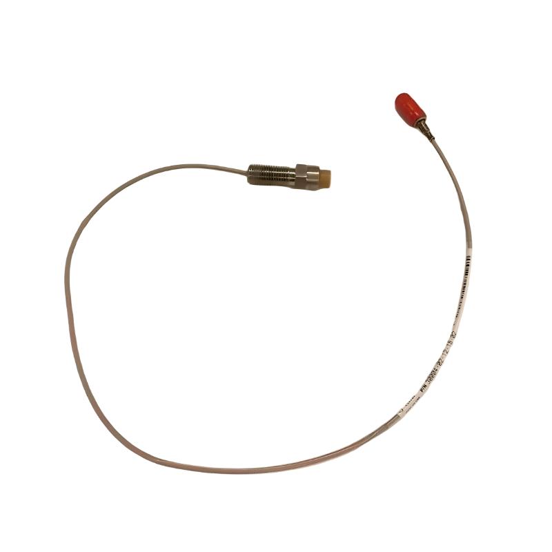
| 330101-00-08-10-02-00 | 3300 XL 8 mm proximity probe; confirm complete configuration | Non-contact shaft displacement and vibration sensing | Probe length, thread, and cable arrangement depend on the complete code | Not reliably confirmed for this exact configuration |
| 330103-00-07-10-02-00 | 3300 XL 8 mm proximity probe; confirm complete configuration | Shaft vibration and relative-position measurement | Depends on probe length, thread, and cable option | Not reliably confirmed for this exact configuration |
| 330104-00-06-10-02-00 | 3300 XL 8 mm proximity probe; confirm complete configuration | Proximity measurement in compatible machinery installations | Depends on the complete probe configuration | Not reliably confirmed for this exact configuration |
| 330180-50-00 | 3300 XL proximity probe family; verify exact model configuration | Non-contact displacement measurement | Depends on probe configuration and mounting style | Not reliably confirmed |
| 3500/42M | Machinery monitoring module | Supports vibration and position monitoring when configured for compatible transducer inputs | Module dimensions depend on the specified hardware and rack arrangement | Not reliably confirmed for the exact module configuration |
The complete model code matters for all five products. Probe thread size, probe length, connector arrangement, calibration, and electrical compatibility should be confirmed before ordering. The dimensions and weights above are intentionally not guessed because those values can vary with the exact hardware configuration.
10. Quick Comparison: Main Product and Related Cable Options
| Comparison item | 330730-080-01-05 | 330730-080-01-00 | 330730-080-00-00 | 330730-040-01-00 |
|---|---|---|---|---|
| Product family | 3300 XL 11 mm | 3300 XL 11 mm | 3300 XL 11 mm | 3300 XL 11 mm |
| Component type | Extension cable | Extension cable | Extension cable | Extension cable |
| Nominal cable length | 8.0 m | 8.0 m | 8.0 m | 4.0 m |
| Armor configuration | Armored | Armored | Unarmored option indicated by code family; verify | Armored |
| Approval option | Multiple approvals associated with suffix “-05”; verify exact approvals | Different suffix; verify | Different suffix; verify | Different suffix; verify |
| Physical dimensions | 8.0 m nominal; assembly drawing required | 8.0 m nominal; assembly drawing required | 8.0 m nominal; assembly drawing required | 4.0 m nominal; assembly drawing required |
| Net weight (kg) | Published values inconsistent; verify | Verify | Verify | Verify |
| Suitable as a direct replacement? | Reference model | Only after compatibility confirmation | Only after compatibility confirmation | Only if the system design permits the different length |
11. Purchasing and Replacement Checklist
When purchasing the 330730-080-01-05, it is useful to check the following details before confirming an order:
1. Complete model number: Ensure every character of the ordering code matches the required part.
2. Cable length: Confirm that the nominal 8.0 m cable is appropriate for the installed probe and sensor arrangement.
3. Armored construction: Confirm that the replacement has the required armor rather than an unarmored cable of similar appearance.
4. Approval requirements: Verify that the supplied unit carries the approvals required for the intended installation. Do not rely on the suffix alone when compliance documentation is required.
5. Connector compatibility: Confirm that the cable connectors match the installed probe and Proximitor sensor.
6. Electrical length: Ensure the complete transducer system is configured for the required electrical length.
7. Dimensions and weight: Obtain the actual assembly drawing and net weight for engineering records, shipping calculations, and installation planning.
8. Product condition: Check the cable jacket, armor, connectors, and packaging for signs of damage before installation.
9. Documentation: Retain the model number, serial or batch identification if provided, inspection records, and installation details.
10. Functional verification: After installation, verify that the complete measurement channel produces plausible readings and follows the site’s approved commissioning procedure.
12. Conclusion
The Bently Nevada 330730-080-01-05 is an armored extension cable associated with the 3300 XL 11 mm proximity measurement family. Its nominal 8.0 m length, triaxial electrical construction, FEP insulation, stainless-steel armor, and defined capacitance make it a component intended for use in compatible industrial machinery monitoring installations.
Its primary value lies in providing a suitable electrical connection between the proximity probe and its associated sensor interface while offering additional mechanical protection along the cable route. Correct selection and installation help maintain the integrity of the complete proximity measurement system.
For replacement or procurement, the most important checks are the complete model number, nominal length, armor configuration, electrical compatibility, connector arrangement, and applicable approvals. The exact dimensions and net weight should be confirmed from the specific assembly documentation, because available product listings provide inconsistent weight figures.