

ProductPRODUCT
Featured products
Contact Us
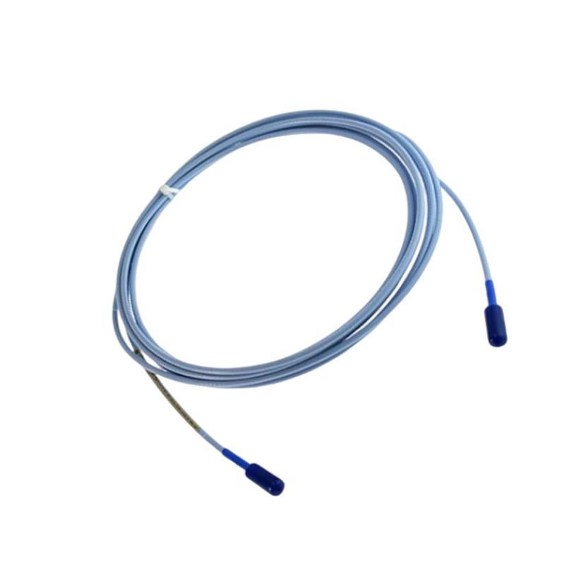
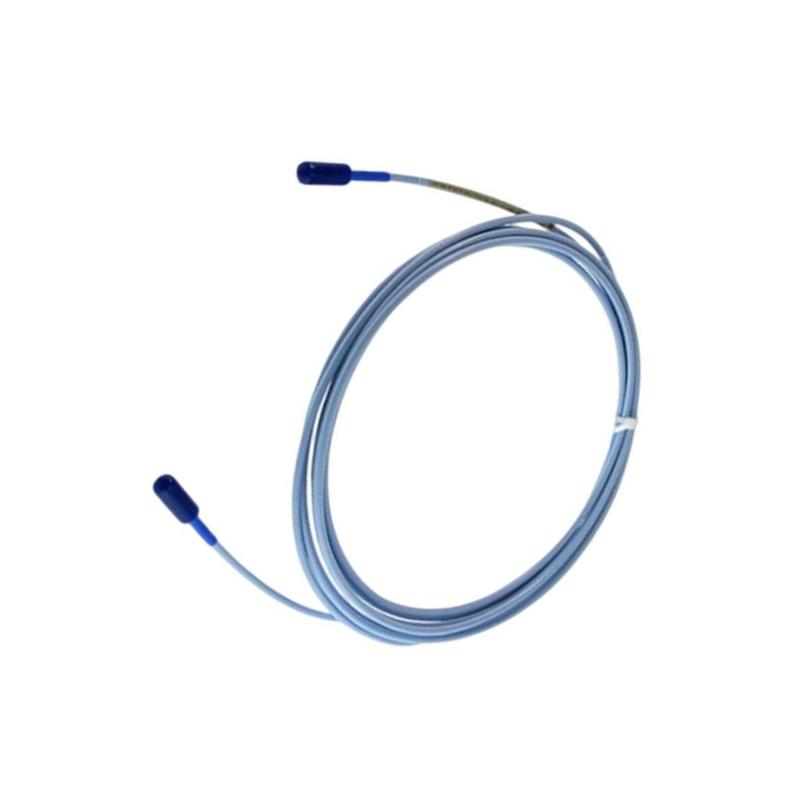
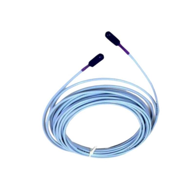
- Bently Nevada
- 330730-040-030-00
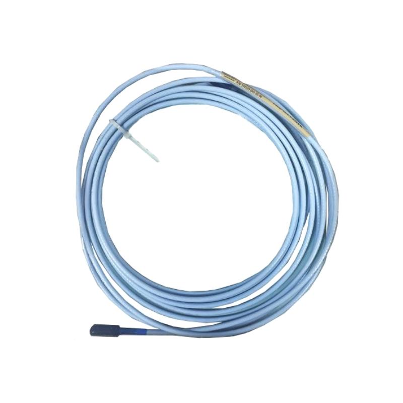
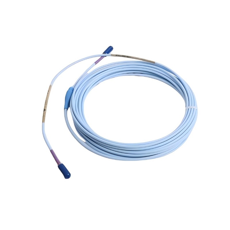
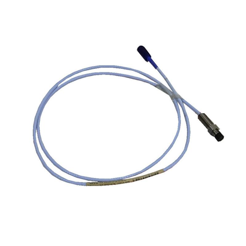
- 3300 XL 11mm Extension Cable
- USA
- 4.0 m
- 1kg
- Xiamen, China
- New & In Stock
- T/T, PayPal, Western Union
- 1 Year
- 1-3 Working Days
- DHL, UPS, TNT, FedEx and EMS.
- 24-Hour Service
- COO
- 3
Our advantage

Global Logistics
We have a 10-year logistics and express cooperation agreement, so our products can be shipped to any place in the world.

Brand new and original
Our products are imported in bulk from the place of origin. Because of the cooperative relationship, our products are all original and 100% new.

24-hour service
We provide 7*24 hours service to our customers. We will be there whenever you need us.

Price advantage
All our products are priced very favorably because we have our own warehouse and supply.
| Company Information | |||
| [email protected] | |||
| Mobile | +8615980777398 | ||
| +8615980777398 | |||
| 15980777398 |
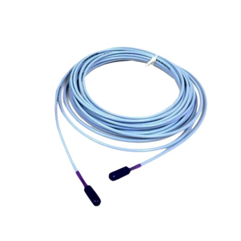
Bently Nevada 330730-040-030-00 — Product Description, Technical Specifications, Applications, Advantages, and Related Models
1. Product Overview
The Bently Nevada 330730-040-030-00 is a model designation associated with the 3300 XL proximity probe extension-cable product family. Before ordering, the complete part number should be checked against the equipment nameplate or original order documentation, because the supplied designation may contain a formatting difference from the standard ordering code.
The 3300 XL product family is used in machinery condition-monitoring systems, particularly for measuring shaft displacement and vibration through a compatible proximity probe and sensor interface. Extension cables form part of the signal path between the probe and the associated proximity sensor system.
An extension cable is not normally a standalone measuring instrument. It is selected to work with a compatible probe, sensor, cable length, connector arrangement, and monitoring instrument. These details matter because an incorrect combination can affect signal calibration, measurement accuracy, or system compatibility.
2. Product Technical Parameters
The following table separates the general characteristics of the 3300 XL extension-cable family from information that requires confirmation for the exact supplied designation. Exact dimensional and weight figures should not be assumed from the model number alone.
| Parameter | Technical description |
|---|---|
| Brand | Bently Nevada |
| Product model supplied | 330730-040-030-00 |
| Product family | 3300 XL |
| Product category | Proximity probe extension cable |
| Primary function | Transmits the electrical signal between compatible proximity-system components |
| Measurement system | Eddy-current proximity measurement system, when used with compatible components |
| Typical monitored quantity | Relative shaft vibration and displacement |
| Installation location | Industrial machinery monitoring installations |
| System configuration | Compatible proximity probe, extension cable, sensor interface, and monitoring equipment |
| Cable length | Must be confirmed against the complete ordering code |
| Cable construction | Depends on the exact cable version and ordering configuration |
| Connector type | Must be confirmed for the specified part number |
| Cable outer diameter | Exact value not confirmed for this designation |
| Overall dimensions | Cable length and connector dimensions must be verified from the applicable product drawing |
| Product weight | Exact weight not confirmed for this designation; verify using the manufacturer’s packing or dimensional data |
| Weight unit | kg |
| Operating temperature | Must be confirmed against the applicable cable version and installation requirements |
| Electrical compatibility | Must match the associated probe and proximity sensor system |
| Installation method | Routed and secured according to the machinery installation design |
| Typical application | Turbines, compressors, pumps, motors, and other rotating machinery |
| Maintenance requirement | Inspection of cable condition, connector engagement, routing, and signal stability |
| Replacement requirement | Match the original part number, cable length, connector configuration, and system compatibility |
Important dimensional note: Extension cables are flexible components, so their physical dimensions are usually described by cable length and cable diameter rather than by conventional length × width × height. A packaged product may have different dimensions and weight from the cable itself. For procurement, the exact cable length, connector dimensions, and net weight should be confirmed rather than estimated.
3. Product Introduction
The 3300 XL extension-cable family is intended for use in industrial proximity measurement systems. These systems are commonly installed on rotating machinery to monitor the relationship between a shaft and a stationary probe. The probe detects changes in the distance between its sensing tip and the target surface, while the associated electronics convert the probe’s response into a usable measurement signal.
In a typical installation, the probe is positioned near the shaft or another suitable conductive target. The extension cable connects the probe to the compatible sensor interface. The sensor system then supplies a signal to a monitoring instrument, which can display measurements, record operating trends, or initiate alarms when configured limits are exceeded.
The extension cable therefore has an important role in maintaining a stable electrical connection throughout the measurement chain. Although it does not independently determine vibration or displacement, its electrical characteristics, mechanical condition, connector quality, and compatibility with the rest of the system all contribute to reliable operation.
For maintenance teams, using the correct replacement cable is particularly important. A cable that appears physically similar may differ in length, electrical characteristics, connector arrangement, or approved system configuration. A replacement should therefore be selected using the complete part number and the existing installation documentation.
4. Product Applications
4.1 Steam and gas turbines
Proximity measurement systems are widely used in turbine installations to monitor shaft vibration and relative shaft position. Extension cables provide the electrical connection required between compatible probes and sensor electronics.
Continuous monitoring can help operators identify changes in machinery behavior, investigate abnormal vibration trends, and schedule maintenance before a developing problem becomes more serious.
4.2 Centrifugal compressors
Compressors operate under demanding mechanical and thermal conditions. Shaft vibration monitoring can help maintenance teams identify changes associated with rotor imbalance, misalignment, bearing deterioration, or other mechanical issues.
A correctly specified extension cable helps preserve the intended signal connection between the proximity probe and its associated electronics.
4.3 Industrial pumps
Large process pumps and other critical rotating machines may use proximity systems to monitor shaft movement. In these installations, cable routing and protection are important because the cable may be exposed to vibration, heat, oil, moisture, or restricted installation space.
The cable should be selected according to the original system configuration and the conditions at the installation site.
4.4 Electric motors and drive equipment
Some large motors and other rotating electrical machines use shaft displacement or vibration monitoring. An extension cable can connect the installed probe to the compatible monitoring system, allowing the machine’s operating condition to be observed over time.
The specific measurement arrangement depends on the machine design and the monitoring equipment being used.
4.5 Industrial condition-monitoring systems
In continuous process facilities, proximity probes and their associated electronics are often integrated into larger condition-monitoring systems. These systems can help engineers review vibration trends, identify abnormal operating conditions, and coordinate inspection or maintenance work.
A suitable extension cable supports the electrical continuity of the measurement chain and helps avoid problems caused by incompatible or damaged connections.
5. Product Advantages
5.1 Supports continuous machinery monitoring
When installed as part of a compatible proximity measurement system, the extension cable allows the probe signal to reach the associated sensor electronics. This supports continuous monitoring of rotating machinery and the collection of operational data over time.
5.2 Designed for integration into a dedicated measurement system
The 3300 XL family is intended for industrial machinery monitoring applications. Selecting the correct extension cable allows it to be incorporated into a system designed around compatible probes and sensor electronics.
5.3 Helps maintain signal continuity
A correctly specified cable provides the required electrical path between system components. Proper connector engagement, secure routing, and protection against mechanical damage help maintain consistent operation.
5.4 Supports maintenance and replacement work
For facilities already using compatible 3300 XL equipment, identifying the correct extension-cable configuration can simplify maintenance planning and replacement procedures.
Keeping the full part number, installed cable length, and connector details in maintenance records can reduce the risk of ordering an unsuitable replacement.
5.5 Suitable for industrial installation requirements
The appropriate cable version can be selected according to the installation’s routing, environmental, and mechanical requirements. Where a cable is exposed to movement, abrasion, heat, or other hazards, the selected construction should be appropriate for those conditions.
5.6 Contributes to measurement-system reliability
The quality of a proximity measurement depends on the complete system, not just the probe. A suitable extension cable, correctly matched components, sound connections, and proper installation all help support reliable measurements.
5.7 Helps reduce avoidable maintenance errors
Using a verified part number and maintaining consistent spare-parts records can help technicians avoid replacing a cable with a different length or connector configuration.
This is particularly useful in plants where several similar monitoring channels are installed on different machines.
6. Installation and Maintenance Considerations
Before installation, confirm the complete ordering code and compare it with the existing cable. Check the required length, connector type, system compatibility, and any environmental or mechanical requirements specified for the equipment.
During installation, avoid sharp bends, excessive tension, crushing, and contact with hot or moving machine components. Secure the cable according to the installation design, while allowing the appropriate clearance for equipment movement and maintenance access.
Inspect the connectors for contamination, physical damage, and secure engagement. A connector that is loose or damaged may cause an intermittent signal or an unstable measurement.
If the monitoring system produces abnormal readings after a cable replacement, check the entire signal path rather than assuming the probe itself has failed. Incorrect cable selection, poor connections, routing damage, or a mismatch between system components may all require investigation.
For critical machinery, replacement work should follow the site’s approved maintenance procedures and applicable equipment documentation.
7. Five Related Models in the Same Product Family
The following models are useful starting points when comparing 3300 XL proximity-system components. They are not all interchangeable with the requested extension cable: some are alternative cable configurations, while others are different component types used within a proximity measurement system.
Because the exact designation 330730-040-030-00 has not been verified, the related-model list should be treated as a preliminary selection guide rather than a confirmed compatibility list.
| Model | Product type | Main parameters or characteristics | Dimensions | Weight (kg) |
|---|---|---|---|---|
| 330730-040-00-00 | 3300 XL extension cable | Related extension-cable configuration; confirm cable length, connector arrangement, and ordering options | Flexible cable; exact length and diameter require code verification | Not confirmed |
| 330730-040-03-00 | 3300 XL extension cable | Related cable configuration; verify the complete ordering code and connector options | Flexible cable; exact dimensions require the applicable drawing | Not confirmed |
| 330730-080-03-00 | 3300 XL extension cable | Related cable designation; confirm whether the specified length and construction suit the installed system | Flexible cable; exact dimensions require code verification | Not confirmed |
| 330130-040-00-00 | Proximity probe or related 3300 XL system component designation | Candidate for comparison within the proximity measurement system; verify exact product type and ordering code | Depends on the actual component and probe configuration | Not confirmed |
| 330180-50-00 | Proximity sensor or related system component designation | Candidate for checking system architecture and compatibility; confirm the exact component specification | Depends on the actual component configuration | Not confirmed |
How to select among related models
The first three entries are intended as starting points for comparing extension-cable configurations. Before selecting one, confirm the required cable length, connector configuration, and system compatibility.
The last two entries are included as related-system comparison candidates rather than direct replacement cables. They should not be substituted for an extension cable unless the maintenance documentation specifically identifies them as the required component.
Exact cable dimensions and net weight are not provided here because those values have not been verified for each complete designation. Using estimated values as if they were manufacturer specifications could lead to incorrect purchasing or installation decisions.
8. Five Commonly Referenced Models from the Same Brand
The following table lists additional Bently Nevada model designations associated with machinery monitoring and protection applications. These are useful candidates for comparing system components, but they represent different functions and should not be treated as direct replacements for the requested extension cable.
| Model | Product category | Main parameters or characteristics | Dimensions | Weight (kg) |
|---|---|---|---|---|
| 330103-00-07-10-02-CN | Proximity probe family candidate | Probe-related designation; confirm probe length, thread, connector, and system compatibility | Depends on the exact probe configuration | Not confirmed |
| 330106-05-30-10-02-CN | Proximity probe family candidate | Probe-related designation; confirm mounting arrangement and ordering-code interpretation | Depends on the exact probe configuration | Not confirmed |
| 3300/20-XX-XX | Legacy monitoring-system designation placeholder | Represents an incomplete family-style designation, not a confirmed orderable part number; a complete model code is required | Depends on the actual instrument | Not confirmed |
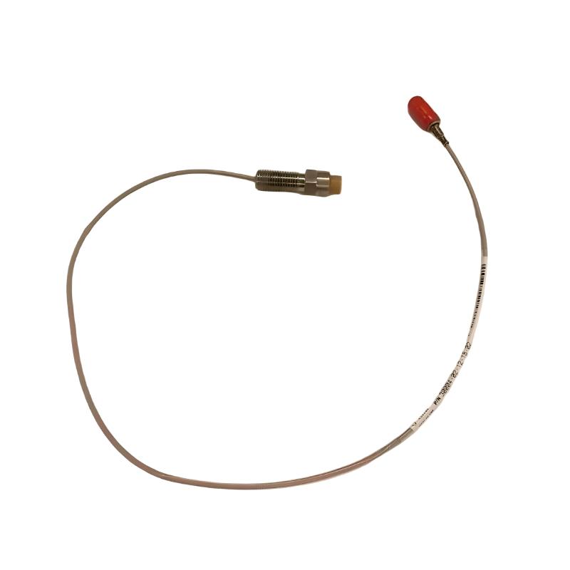
| 3300 XL 11 mm proximity probe system | Proximity measurement system | Uses a compatible probe, extension cable, and sensor electronics to measure shaft displacement | Depends on the selected components | Not confirmed |
| 3300 XL proximity sensor system | Sensor and signal-conditioning system | Provides the interface between compatible proximity probes and the monitoring system | Depends on the selected sensor and installation arrangement | Not confirmed |
Model-number caution: The entry containing XX is a placeholder, not a complete orderable model. It is included only to illustrate that a family designation is insufficient for procurement. A specific instrument model and its complete part number are needed to establish the exact parameters, dimensions, and weight.
The two probe-related designations also require confirmation against the intended component type and ordering code before use in a quotation or bill of materials.
9. Comparison of the Main Product Types
The following table summarizes the differences between an extension cable, a proximity probe, and a sensor interface.
| Component | Primary function | Typical installation position | Key selection parameters | Dimensions | Weight (kg) |
|---|---|---|---|---|---|
| 3300 XL extension cable | Carries the signal between compatible proximity-system components | Between probe and sensor interface | Cable length, connector type, electrical compatibility, cable construction | Cable length and diameter; exact values depend on model | Not confirmed |
| 3300 XL proximity probe | Detects changes in the distance to a suitable conductive target | Mounted near the monitored shaft or target | Probe diameter, length, mounting thread, tip configuration, compatible cable system | Depends on probe size and configuration | Not confirmed |
| 3300 XL proximity sensor | Interfaces with the probe and conditions the measurement signal | Installed according to the monitoring-system design | Probe compatibility, system configuration, output characteristics, installation requirements | Depends on the exact sensor model | Not confirmed |
| Machinery monitoring instrument | Displays, records, or processes monitoring signals | Control cabinet or designated instrument location | Input type, channel configuration, monitoring functions, system integration | Depends on the instrument model | Not confirmed |
10. Procurement Checklist
Before ordering the 330730-040-030-00 or any related model, check the following details:
1. Complete part number: Compare the supplied designation with the original label, drawing, or spare-parts record.
2. Cable length: Confirm the required length from the installed system and the relevant equipment documentation.
3. Connector arrangement: Verify the connector type and end configuration. Similar-looking connectors are not necessarily interchangeable.
4. System compatibility: Check that the cable matches the installed probe, sensor interface, and monitoring equipment.
5. Cable construction: Confirm the required mechanical protection and environmental suitability.
6. Dimensions: Obtain the cable diameter and connector dimensions from the applicable product drawing where these are required for installation.
7. Weight: Request the net product weight and, if required for shipping, the gross packaged weight. Keep these values separate.
8. Operating conditions: Check the temperature range and any other environmental limits specified for the exact cable version.
9. Replacement history: Compare the proposed part with the cable previously installed on the machine.
10. Documentation: Retain the verified model code, drawing revision, and compatibility information in the equipment maintenance record.
11. Final Product Summary
The Bently Nevada 330730-040-030-00 designation appears to refer to a cable-related product associated with the 3300 XL proximity measurement family, but the exact ordering code needs confirmation before its technical specifications can be stated definitively.
Its intended role in a compatible system is to provide the electrical connection between proximity measurement components. Such cables support machinery monitoring applications involving turbines, compressors, pumps, motors, and other rotating equipment.
The main selection considerations are the complete part number, cable length, connector configuration, system compatibility, cable construction, and installation conditions. The cable’s physical dimensions and weight should be obtained from the specification for the exact model rather than inferred from a similar product.
For purchasing or maintenance documentation, the most reliable next step is to verify the full designation from the product label or original parts list. Once the exact code is established, the technical parameters, dimensions, weight in kilograms, and suitable replacement models can be compared consistently without confusing extension cables with probes, sensors, or monitoring instruments.