

ProductPRODUCT
Featured products
Contact Us
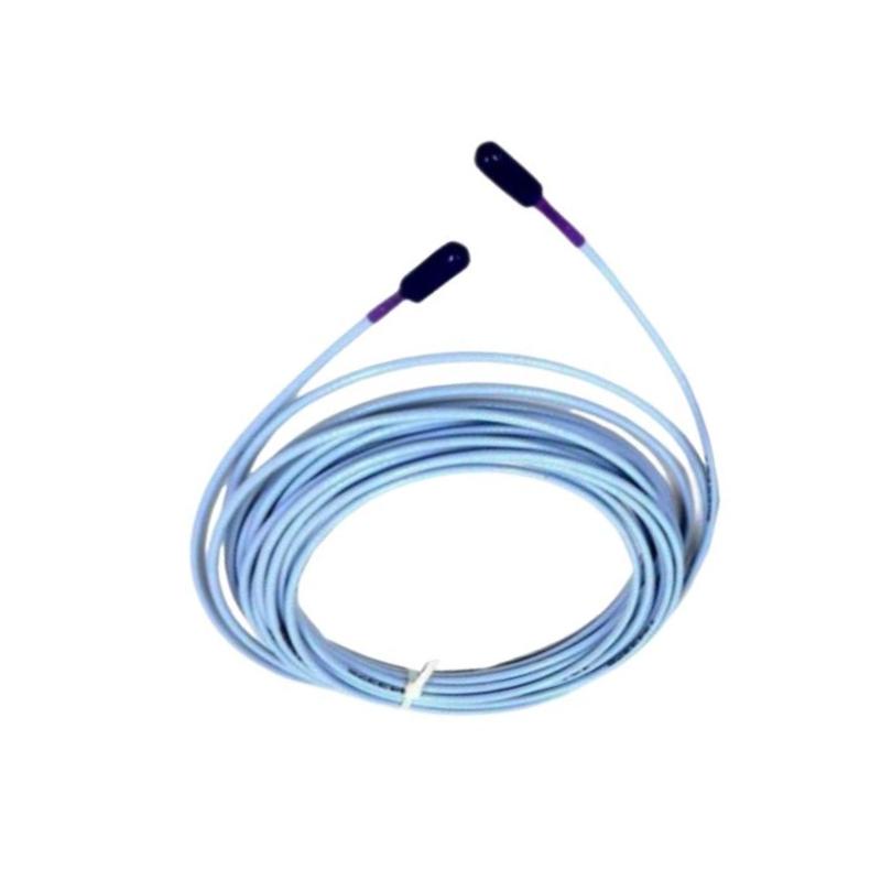
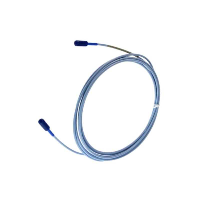
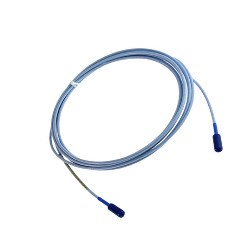
- Bently Nevada
- 330730-040-03
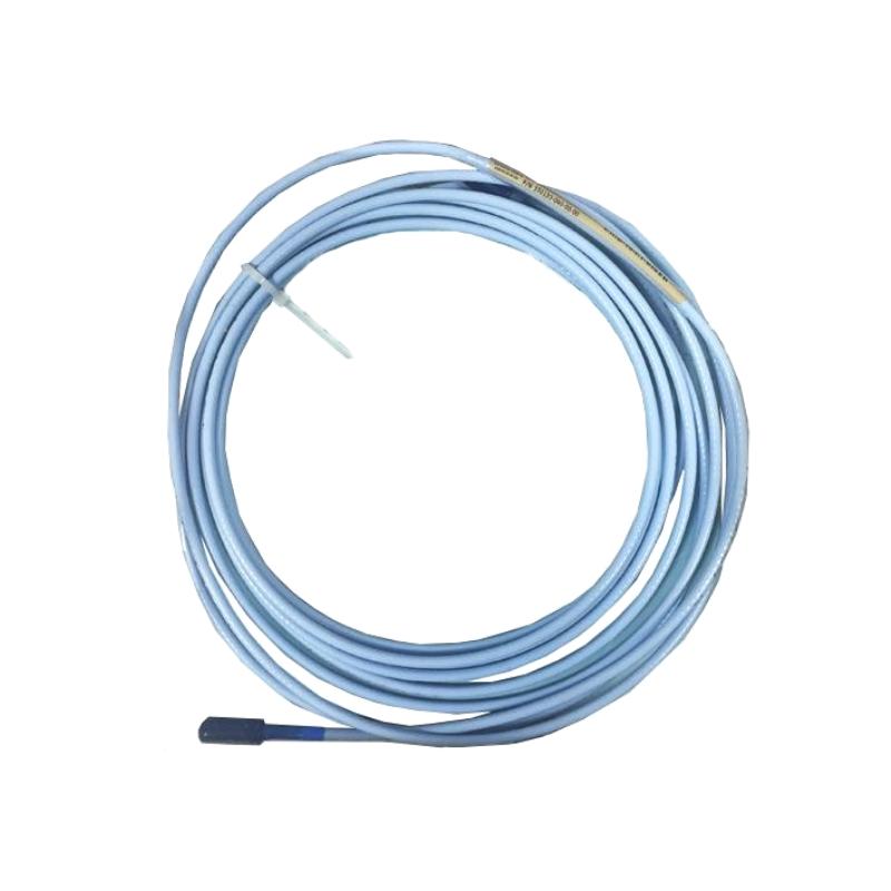
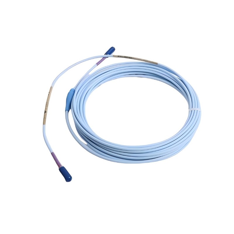
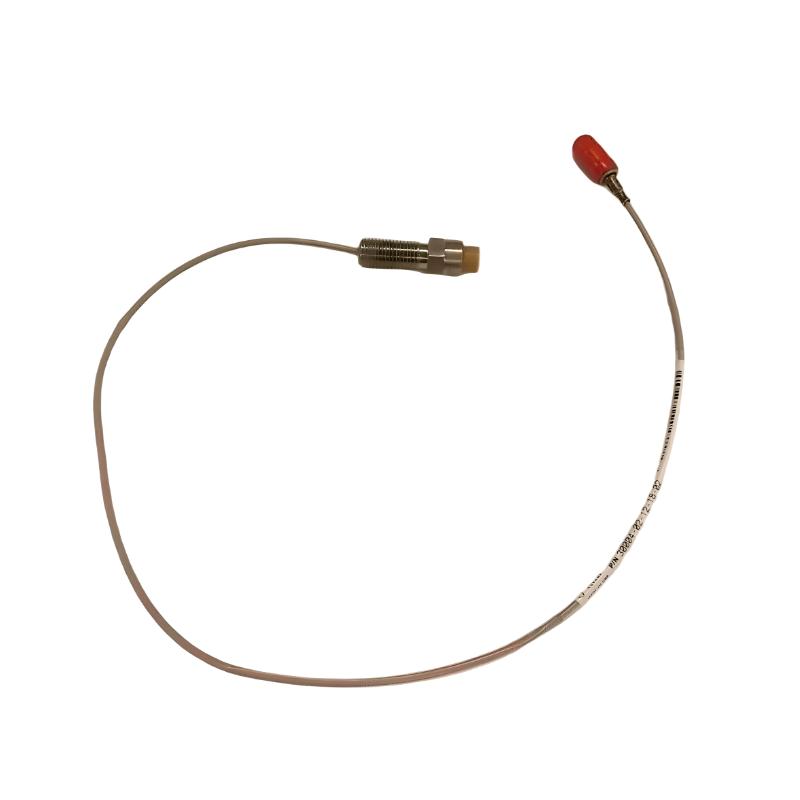
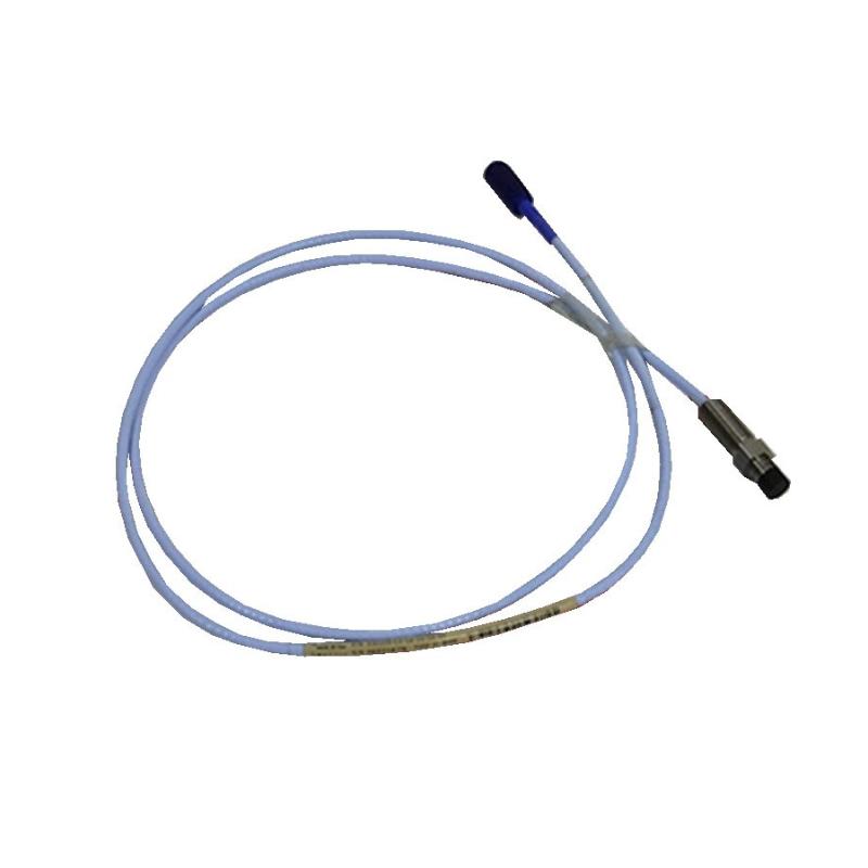
- 3300 XL 11mm Extension Cable
- USA
- 4.0 m
- 1kg
- Xiamen, China
- New & In Stock
- T/T, PayPal, Western Union
- 1 Year
- 1-3 Working Days
- DHL, UPS, TNT, FedEx and EMS.
- 24-Hour Service
- COO
- 4
Our advantage

Global Logistics
We have a 10-year logistics and express cooperation agreement, so our products can be shipped to any place in the world.

Brand new and original
Our products are imported in bulk from the place of origin. Because of the cooperative relationship, our products are all original and 100% new.

24-hour service
We provide 7*24 hours service to our customers. We will be there whenever you need us.

Price advantage
All our products are priced very favorably because we have our own warehouse and supply.
| Company Information | |||
| [email protected] | |||
| Mobile | +8615980777398 | ||
| +8615980777398 | |||
| 15980777398 |
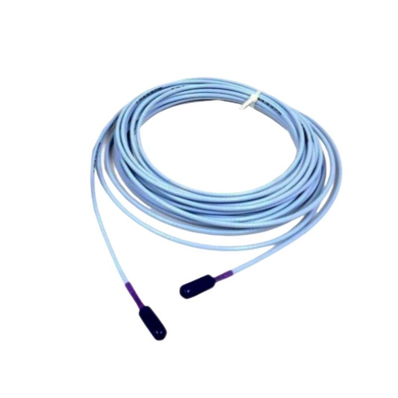
Bently Nevada 330730-040-03 Industrial Extension Cable: Technical Specifications, Product Description, Applications, Advantages, and Related Models
1. Product Overview
The Bently Nevada 330730-040-03 is a model designation associated with industrial proximity transducer extension cable applications. Extension cables are used in machinery monitoring systems to connect a proximity probe to its corresponding signal-conditioning component, allowing the system to transmit the electrical signal required for shaft displacement and vibration monitoring.
In industrial environments, reliable connections between sensing components are essential for maintaining stable measurement performance. The extension cable must match the probe, signal conditioner, electrical characteristics, connector arrangement, and installation requirements of the complete system.
The exact configuration of 330730-040-03 should be confirmed before ordering. Unlike a complete part number with all applicable suffixes, this shortened designation may not identify every ordering option, connector-protection feature, or approval requirement. The descriptions below distinguish general product-family characteristics from details that require confirmation for the exact model.
Basic Product Information
| Parameter | Description |
|---|---|
| Brand | Bently Nevada |
| Model | 330730-040-03 |
| Product category | Industrial instrumentation extension cable |
| Product family | 3300 XL proximity transducer product family, subject to model confirmation |
| Product function | Electrical interconnection between compatible transducer components |
| Typical system application | Proximity-based shaft displacement and vibration monitoring |
| Nominal cable length | The 040 designation is associated with a 4.0 m cable configuration; verify the complete ordering code |
| Equivalent length | Approximately 13.1 ft if the cable length is 4.0 m |
| Cable construction | Exact construction requires confirmation |
| Cable impedance | Requires confirmation for the exact configuration |
| Insulation material | Requires confirmation |
| Connector arrangement | Requires confirmation |
| Connector protection | Requires confirmation |
| Operating temperature | Requires the exact model specification |
| Overall dimensions | Cable length and connector dimensions require confirmation |
| Net weight (kg) | Requires confirmation from the exact product specification |
| Installation type | Fixed industrial instrumentation installation |
| Typical equipment | Compatible turbines, compressors, pumps, generators, and other rotating machinery |
| Replacement requirement | Must match the installed probe, cable, and signal-conditioning system |
2. Detailed Technical Parameters
The following table provides a practical technical reference for identifying the cable, planning an installation, and preparing purchasing documentation. Parameters that depend on the exact ordering configuration are marked for confirmation rather than assigned unsupported values.
| Technical parameter | Specification or description |
|---|---|
| Full model designation | 330730-040-03 |
| Product type | Extension cable, subject to confirmation of the complete part number |
| Product series | 3300 XL family, subject to confirmation |
| Nominal cable length | Potentially 4.0 m; verify the ordering code |
| Length in millimeters | 4,000 mm if the nominal length is confirmed as 4.0 m |
| Length in feet | Approximately 13.1 ft if the nominal length is 4.0 m |
| Cable construction | Exact construction requires confirmation |
| Cable impedance | Requires confirmation |
| Nominal capacitance | Requires confirmation |
| Insulation material | Requires confirmation |
| Conductor arrangement | Requires confirmation |
| Connector type | Requires confirmation |
| Connector protection | Requires confirmation |
| Cable outside diameter | Not established |
| Connector dimensions | Not established |
| Minimum bend radius | Follow the approved specification for the exact cable |
| Operating temperature | Requires confirmation |
| Net weight (kg) | Not established |
| Shipping weight (kg) | Not established |
| Packaging dimensions | Not established |
| Installation environment | Must comply with the specified temperature, chemical exposure, moisture, and mechanical limits |
| Electrical compatibility | Must match the complete probe and signal-conditioning configuration |
| Maintenance requirements | Periodic inspection of connectors, cable condition, routing, and mechanical protection |
2.1 Cable Length and Installation Space
If the 040 portion of the model number identifies a 4.0 m cable, the nominal length provides a connection distance of 4,000 mm between the relevant transducer components.
The actual routing distance should be evaluated before installation. The cable must reach the intended connection points without excessive tension, sharp bends, or interference with moving machinery.
The overall installation space also depends on connector dimensions, cable supports, protective conduits, and access required for future maintenance.
2.2 Electrical Characteristics
The electrical properties of an extension cable are important in a proximity measurement system because the cable forms part of the probe’s electrical circuit.
Impedance, capacitance, cable length, and connector compatibility must be considered together. Selecting a cable based only on its physical appearance or nominal length may result in an unsuitable combination.
Before replacement, verify that the cable is approved for the specific probe and signal conditioner in the existing installation.
2.3 Environmental and Mechanical Characteristics
Industrial cable assemblies may be exposed to vibration, temperature changes, oil, moisture, abrasion, and incidental physical contact.
The suitability of model 330730-040-03 for these conditions depends on its exact construction. Mechanical protection, connector protection, and environmental approvals should be confirmed rather than inferred from the shortened model designation.
2.4 Dimensions and Weight
For technical purchasing records, the following information should be obtained for the exact supplied configuration.
| Measurement | Required information |
|---|---|
| Cable length | Confirm nominal length in meters |
| Cable outside diameter | Confirm in millimeters |
| Connector length | Confirm in millimeters |
| Connector diameter | Confirm in millimeters |
| Overall assembly dimensions | Confirm from the applicable drawing |
| Minimum bend radius | Confirm the permitted installation value |
| Net weight (kg) | Confirm the actual product weight |
| Shipping weight (kg) | Confirm if freight calculations are required |
| Package length × width × height | Confirm the shipping package dimensions |
An exact net weight cannot be established reliably from the shortened model number alone. The weight should not be estimated and then presented as a certified specification.
3. Product Introduction
The 330730-040-03 designation should be treated as a model requiring full configuration identification. If confirmed as an extension cable within the 3300 XL proximity transducer family, its primary purpose is to provide the electrical connection between a compatible proximity probe and its associated Proximitor Sensor.
A proximity monitoring system measures the relationship between a probe and a conductive target, commonly a rotating machine shaft. The probe responds to changes in the gap, and the signal-conditioning component processes the electrical response to provide a usable measurement signal.
The extension cable does not perform the measurement independently. Instead, it helps maintain the electrical connection required for the complete system to function.
3.1 Main Product Functions
| Function | Description |
|---|---|
| Electrical interconnection | Connects compatible components in the transducer system |
| Signal transmission | Carries the probe signal to the corresponding signal-conditioning component |
| Installation flexibility | Allows components to be installed at separate positions within the permitted cable length |
| Connector interface | Provides the specified connection between the relevant system components |
| System maintenance | Can be replaced when a compatible cable is damaged or requires replacement |
| Support for monitoring | Contributes to the operation of the complete shaft monitoring arrangement |
3.2 Working Principle
The working principle of the complete proximity measurement system can be divided into three stages.
Stage 1: Target detection
A proximity probe is installed near a conductive target. As the target moves relative to the probe, the distance between the probe tip and the target changes.
Stage 2: Electrical signal transmission
The extension cable connects the probe to the appropriate signal-conditioning component. The cable must have the electrical and mechanical characteristics required by the intended system.
Stage 3: Signal processing
The Proximitor Sensor processes the probe’s electrical response and provides a corresponding output to compatible monitoring equipment.
The resulting measurements can be used to monitor shaft displacement or vibration, depending on the system design and the parameters configured for the monitoring application.
4. Product Applications
4.1 Power Generation
Power generation facilities use turbines, generators, pumps, and other rotating machinery that may require continuous condition monitoring.
Where a compatible proximity transducer system is installed, an appropriate extension cable helps maintain the connection between the probe and the signal-conditioning component.
Typical applications include:
-
Steam turbine shaft monitoring.
-
Generator shaft displacement measurement.
-
Auxiliary pump monitoring systems.
-
Turbine-driven rotating equipment.
-
Replacement of damaged instrumentation cables.
4.2 Oil and Gas
Oil and gas installations commonly use compressors, pumps, turbines, and other rotating machinery.
A correctly specified extension cable can support existing proximity measurement systems used for machinery condition monitoring. Cable selection must account for the complete transducer configuration and the environmental requirements of the installation.
Typical applications include compressor monitoring, process pump monitoring, and maintenance of existing machinery instrumentation.
4.3 Petrochemical Processing
Petrochemical plants may operate rotating equipment continuously under demanding operating conditions.
An extension cable may be used to connect compatible sensing components in these installations. Cable routing, insulation condition, connector protection, and temperature limits should be evaluated as part of the installation.
4.4 Industrial Manufacturing
Manufacturing facilities use motors, pumps, fans, compressors, and other rotating equipment throughout production processes.
Where proximity measurement is part of the installed monitoring system, a compatible extension cable supports the connection needed for shaft movement measurements.
It may be used during equipment maintenance, instrumentation replacement, and restoration of an existing monitoring circuit.
4.5 Heavy Industry
Large rotating machines used in metal processing, mining, and other heavy industrial applications may require shaft monitoring.
The suitability of this cable designation depends on its actual construction and compatibility with the installed equipment. Mechanical protection may be necessary where the cable is exposed to abrasion or incidental impact.
4.6 Spare Parts Management
The model is also relevant to maintenance departments responsible for managing instrumentation spare parts.
Maintaining an accurately identified replacement cable can help reduce troubleshooting time. However, the complete part number should be checked before procurement to avoid substituting a cable with incompatible electrical or mechanical characteristics.
5. Product Advantages
The following advantages describe the potential benefits of a correctly specified extension cable in a compatible monitoring system. They should not be interpreted as independently verified performance claims for every configuration of model 330730-040-03.
5.1 Supports Reliable Electrical Connections
A correctly selected cable helps maintain the electrical connection between the proximity probe and signal-conditioning component.
This is important because loose connectors, damaged insulation, and incompatible cable characteristics can interfere with the measurement circuit.
5.2 Provides Installation Flexibility
An extension cable allows the probe and signal-conditioning component to be positioned according to the machinery layout.
The selected cable length should be sufficient for the installation while avoiding excessive slack or tension.
5.3 Supports Existing Monitoring Equipment
When the model is confirmed as compatible with the installed system, replacement of the extension cable may allow an existing monitoring arrangement to be maintained without changing the entire system.
5.4 Simplifies Maintenance Planning
Recording the complete cable model, connector configuration, and associated probe model helps maintenance teams identify suitable spare parts.
This can reduce ordering errors and simplify troubleshooting when a connection fault is suspected.
5.5 Contributes to Continuous Monitoring
The cable forms part of the signal path used by the complete monitoring system.
When all components are correctly specified and installed, the cable supports the transmission of signals used for machinery condition monitoring.
5.6 Allows Configuration-Based Selection
Different cable configurations may accommodate different lengths, routing requirements, and mechanical protection needs.
The exact available options for this particular designation must be confirmed before choosing an alternative.
6. Brand and Product Series
| Parameter | Description |
|---|---|
| Brand | Bently Nevada |
| Model | 330730-040-03 |
| Potential product series | 3300 XL, subject to confirmation of the complete part number |
| Potential product category | Proximity transducer extension cable |
| Typical measurement system | Eddy-current proximity measurement |
| Primary function | Electrical connection between compatible transducer components |
| Typical industries | Power generation, oil and gas, petrochemical processing, and industrial manufacturing |
| Typical equipment | Turbines, compressors, pumps, generators, and other compatible rotating machinery |
The 3300 XL product family includes components designed for proximity measurement applications. Different models serve different functions, including target detection, signal transmission, and signal conditioning.
The exact series designation for model 330730-040-03 should be confirmed before it is used in a formal technical catalog or purchase specification.
7. Five Related Models for Technical Comparison
The following table lists potential related cable configurations previously associated with the 330730 product designation. These are candidate model numbers for verification, not confirmed interchangeable replacements.
| Model | Potential product type | Nominal length | Construction | Dimensions | Weight (kg) |
|---|---|---|---|---|---|
| 330730-040-00-CN | Extension cable | Potentially 4.0 m | Requires confirmation | Cable and connector dimensions unconfirmed | Unconfirmed |
| 330730-040-01-00 | Extension cable | Potentially 4.0 m | Requires confirmation | Cable and connector dimensions unconfirmed | Unconfirmed |
| 330730-040-03-00 | Extension cable | Potentially 4.0 m | Requires confirmation | Cable and connector dimensions unconfirmed | Unconfirmed |
| 330730-080-00-CN | Extension cable | Potentially 8.0 m | Requires confirmation | Cable and connector dimensions unconfirmed | Unconfirmed |
| 330730-080-01-00 | Extension cable | Potentially 8.0 m | Requires confirmation | Cable and connector dimensions unconfirmed | Unconfirmed |
7.1 Selection Considerations
330730-040-00-CN
Consider this model for comparison if the required installation uses a cable of similar nominal length. Verify the complete connector configuration and electrical specifications before selecting it.
330730-040-01-00
Evaluate this candidate if the installation requires a particular form of mechanical protection. The construction and compatibility must be confirmed before purchase.
330730-040-03-00
This designation may be relevant when comparing alternative configurations in the same apparent model family. The exact product definition should be checked before assuming it provides a specific connector-protection arrangement.
330730-080-00-CN
A longer cable configuration may be relevant where the physical routing distance is greater. Confirm that the complete cable length is permitted for the specified probe and signal-conditioning system.
330730-080-01-00
This candidate may be considered for a longer cable run where additional mechanical protection is required, provided its actual construction and system compatibility meet the installation requirements.
8. Five Additional Models for Broader System Comparison
The following models represent potential alternatives or related components within the broader proximity monitoring product range. They are not all direct replacements for the target cable.
| Model | Product category | Primary function | Dimensions | Weight (kg) |
|---|---|---|---|---|
| 330106-05-30-10-02-CN | Proximity probe designation | Non-contact measurement of target distance, subject to exact model confirmation | Probe length and thread dimensions unconfirmed | Unconfirmed |
| 330103-00-07-10-02-CN | Proximity probe designation | Proximity sensing, subject to exact model confirmation | Probe length and thread dimensions unconfirmed | Unconfirmed |
| 330180-50-00 | Proximitor Sensor designation | Signal conditioning for a compatible proximity system, subject to model confirmation | Enclosure dimensions unconfirmed | Unconfirmed |
| 330130-040-00-00 | Extension cable designation | Cable interconnection in a compatible transducer system, subject to model confirmation | Cable and connector dimensions unconfirmed | Unconfirmed |
| 330780-51-00 | Related instrumentation designation | Exact product type and function require confirmation | Unconfirmed | Unconfirmed |
These models should be treated as preliminary comparison candidates. Their exact product descriptions, electrical specifications, and ordering configurations must be established before they are included as approved alternatives in a purchasing specification.
9. Installation and Maintenance
9.1 Before Installation
-
Confirm the complete model number and all suffixes.
-
Check compatibility with the installed probe and signal-conditioning component.
-
Inspect the cable and connectors for visible damage.
-
Verify the required cable length and routing path.
-
Confirm the applicable temperature and environmental limits.
-
Check the installation drawing and connector requirements.
9.2 During Installation
-
Avoid sharp bends and excessive pulling force.
-
Keep the cable away from moving machinery.
-
Protect the cable from abrasion and sharp edges.
-
Use appropriate supports and routing protection.
-
Ensure connectors are installed according to the applicable instructions.
-
Preserve adequate access for future inspection and replacement.
9.3 During Routine Maintenance
-
Inspect the cable jacket for cuts or deterioration.
-
Check connectors for looseness or contamination.
-
Investigate unstable measurements and intermittent signals.
-
Verify the cable connection before replacing other system components.
-
Record the full model number of any replacement cable.
-
Use only a configuration approved for the installed monitoring system.
A damaged cable can affect signal reliability, but similar symptoms may also result from probe faults, connector problems, incorrect installation, or failures elsewhere in the monitoring system.
10. Purchasing Checklist
| Item | Information required |
|---|---|
| Complete model number | Confirm all characters and suffixes |
| Product description | Confirm whether the item is an extension cable |
| Product series | Confirm the exact series designation |
| Cable length | Confirm the nominal length in meters |
| Cable construction | Confirm the specified construction |
| Electrical parameters | Verify impedance and other applicable characteristics |
| Connector configuration | Confirm connector type and protection |
| Operating temperature | Obtain the exact permitted range |
| Overall dimensions | Obtain cable and connector measurements |
| Net weight (kg) | Obtain the confirmed product weight |
| Packaging dimensions | Confirm if required for shipping |
| Compatibility | Verify the complete probe, cable, and signal-conditioning arrangement |
| Environmental requirements | Confirm suitability for the intended installation |
11. Conclusion
Bently Nevada 330730-040-03 is a model designation that requires complete configuration identification before its technical characteristics can be stated definitively.
If confirmed as an extension cable within the intended proximity transducer product family, its role is to provide the electrical connection required between compatible sensing and signal-conditioning components. Its suitability depends on cable length, construction, electrical characteristics, connectors, environmental limits, and system compatibility.
The related model tables provide a preliminary framework for comparing possible alternatives and associated instrumentation components. However, exact dimensions and net weight in kilograms remain unconfirmed for the listed configurations and should not be represented as certified specifications.
For an accurate product catalog, purchase order, or engineering record, confirm the complete ordering code and the applicable technical specifications before finalizing the description.