

ProductPRODUCT
Featured products
Contact Us
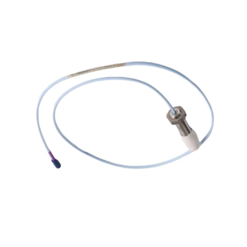
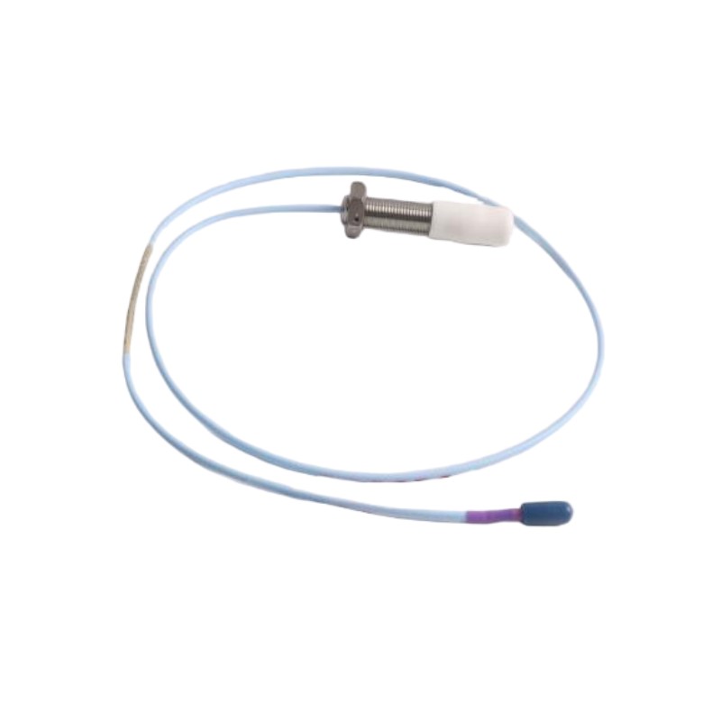
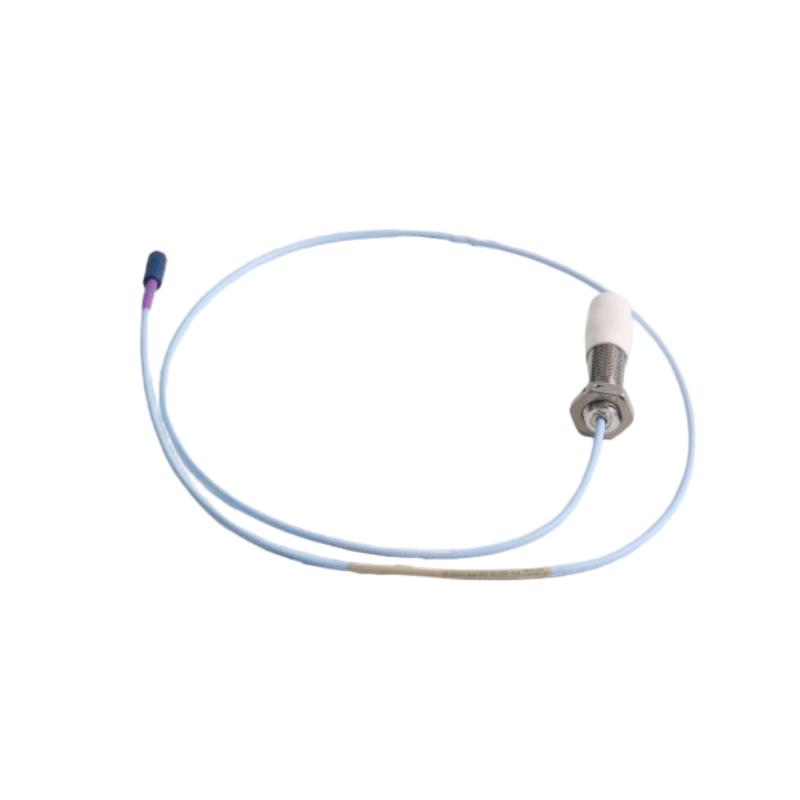
- Bently Nevada
- 330709-010-060-10-02-00
- 3300 XL 11mm Proximity Probe
- USA
- 60 mm
- 0.2kg
- Xiamen, China
- New & In Stock
- T/T, PayPal, Western Union
- 1 Year
- 1-3 Working Days
- DHL, UPS, TNT, FedEx and EMS.
- 24-Hour Service
- COO
- 7
Our advantage

Global Logistics
We have a 10-year logistics and express cooperation agreement, so our products can be shipped to any place in the world.

Brand new and original
Our products are imported in bulk from the place of origin. Because of the cooperative relationship, our products are all original and 100% new.

24-hour service
We provide 7*24 hours service to our customers. We will be there whenever you need us.

Price advantage
All our products are priced very favorably because we have our own warehouse and supply.
| Company Information | |||
| [email protected] | |||
| Mobile | +8615980777398 | ||
| +8615980777398 | |||
| 15980777398 |
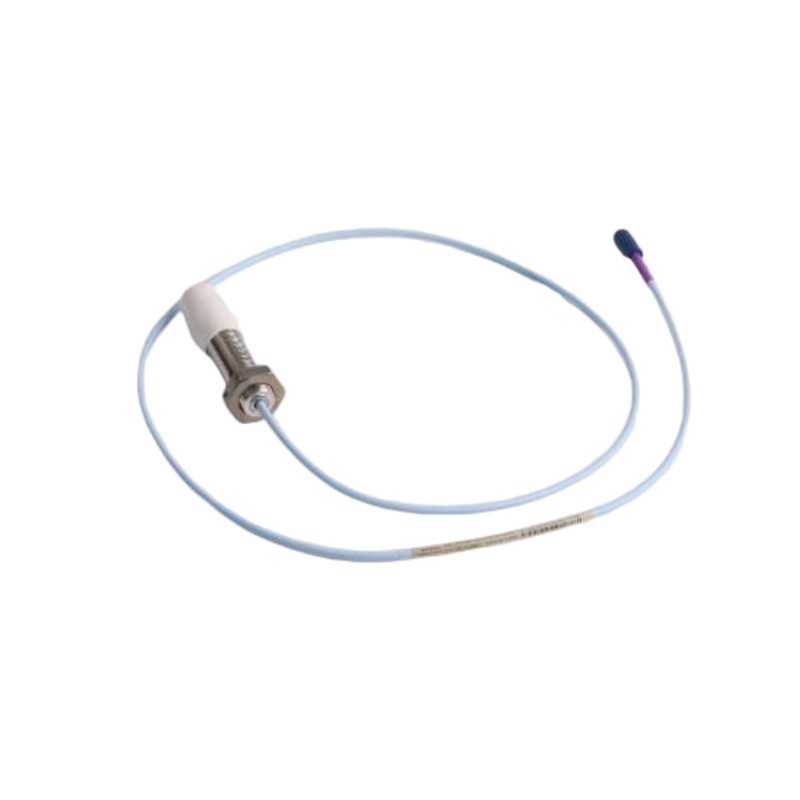
Bently Nevada 330709-010-060-10-02-00 Proximity Probe
1. Product Overview
The Bently Nevada 330709-010-060-10-02-00 is a 3300 XL 11 mm proximity probe designed for non-contact measurement of shaft vibration and relative displacement in industrial rotating machinery.
This configuration is distinguished by its 10 mm unthreaded section, 60 mm case-length option, 1.0 m cable option, miniature coaxial ClickLoc connector, and standard approval option. The unthreaded section can affect how the probe fits into a mounting arrangement, so it is important to check the mounting drawing before replacing an existing sensor.
The probe operates using the eddy-current principle. When positioned near a conductive target, such as a compatible steel shaft, it responds to changes in the gap between the target and the probe tip. A compatible Proximitor Sensor and monitoring system process the signal so that shaft movement can be monitored during machine operation.
This product is intended for use as part of a complete measurement system rather than as an independent vibration monitor. The probe, cable, signal conditioner, and monitoring hardware must be selected as a compatible combination to obtain the intended measurement performance.
2. Technical Parameters
| Parameter | Specification |
|---|---|
| Model | 330709-010-060-10-02-00 |
| Brand | Bently Nevada |
| Series | 3300 XL |
| Product family | 11 mm proximity probe |
| Product type | Eddy-current proximity probe |
| Primary function | Non-contact shaft vibration and displacement measurement |
| Sensing principle | Eddy-current electromagnetic measurement |
| Probe diameter class | 11 mm |
| Thread specification | M16 × 1.5 for the corresponding 330709 configuration |
| Unthreaded length | 10 mm, option 010 |
| Case length | 60 mm, option 060 |
| Total cable length option | 1.0 m, option 10 |
| Connector option | Miniature coaxial ClickLoc connector, standard cable, option 02 |
| Agency approval option | 00; no additional agency approval selected in the ordering code |
| Nominal system linear range | Depends on the matched probe system; confirm the applicable 3300 XL 11 mm system specification |
| Typical scale factor | Approximately 3.94 V/mm (100 mV/mil) for a compatible 3300 XL 11 mm system |
| Target material | Electrically conductive material, typically compatible steel |
| Probe tip material | PPS for this probe family |
| Probe case material | Stainless steel; confirm the specific configuration documentation |
| Cable type | 75 Ω FEP-insulated triaxial cable in the compatible system |
| Connector material | Gold-plated brass is used in the corresponding connector family |
| Signal processing | Requires a compatible Proximitor Sensor |
| Monitoring function | Supports shaft vibration, relative displacement, and position monitoring when correctly integrated |
| Mounting style | Threaded probe installation |
| Typical applications | Turbines, compressors, pumps, motors, and other compatible rotating machinery |
| Dimensions | 10 mm unthreaded section; 60 mm case-length option; 1.0 m cable option; full assembled dimensions depend on the mechanical drawing |
| Product weight | Exact weight for this complete option code is not confirmed; obtain the configuration-specific figure before engineering or shipping use |
| Shipping weight | Depends on packaging and accessories; should be recorded separately from bare-product weight |
| Compatibility | Must match the existing probe system, extension cable, Proximitor Sensor, and monitoring channel |
Dimensional clarification: The 010 and 060 options describe different parts of the probe’s mechanical configuration. The 60 mm case-length option should not be treated as the complete assembly length, because the cable and connector extend beyond the case. The exact overall dimensions and weight should be taken from the drawing or product data for this complete ordering code.
3. Product Introduction
The 330709-010-060-10-02-00 is designed for applications where shaft movement must be measured accurately without placing a mechanical sensor in direct contact with the rotating surface. Its eddy-current sensing technology is widely used in industrial machinery monitoring because it can detect small changes in the distance between a probe and a conductive target.
The probe is mounted at a specified distance from the shaft or other suitable target. As the target moves, the gap changes and the probe’s electrical response changes accordingly. When the probe is connected to the correct signal-conditioning equipment, this response can be converted into a measurement representing shaft vibration, displacement, or position.
The 10 mm unthreaded section is an important mechanical feature of this configuration. It affects the relationship between the probe body, mounting hardware, and installation surface. When selecting a replacement, the unthreaded section should be compared with the existing probe rather than checking only the thread diameter or case length.
The 60 mm case-length option provides a defined body length for the installation design. This dimension can influence how the probe sits within a threaded mounting point and how much adjustment is available during setup. The installer must ensure that the probe can be secured properly and positioned at the required measurement gap.
The 1.0 m cable option provides the probe’s integral electrical connection. Its length should be considered together with the location of the signal-conditioning equipment, the routing path, and the cable requirements of the complete transducer system.
The miniature coaxial ClickLoc connector provides the connection interface for the compatible system. The connector should be kept clean and protected from damage during installation and maintenance. It must also match the corresponding cable or system component.
The model is intended for industrial condition monitoring. Its practical value depends not only on the probe itself but also on correct mounting, cable routing, calibration, signal processing, and the monitoring settings used by the machinery protection system.
4. Product Applications
4.1 Shaft vibration measurement
Shaft vibration monitoring is one of the principal applications for an eddy-current proximity probe. In a rotating machine, the shaft may move relative to its bearing housing because of imbalance, misalignment, bearing wear, mechanical looseness, or changes in operating conditions.
The probe measures the changing gap between its tip and the shaft. A compatible monitoring channel can then display the resulting vibration signal and track how it changes over time.
For critical equipment, vibration trends can help maintenance personnel identify unusual behavior before it develops into a more serious mechanical problem. The probe does not independently identify every fault, but it provides useful measurement data for machinery diagnostics.
4.2 Shaft displacement monitoring
The probe can be used to monitor relative shaft displacement when installed in a suitable position and paired with compatible signal-conditioning equipment.
Displacement measurements are useful when the machine’s operating condition depends on maintaining a defined relationship between the shaft and a stationary reference point. Changes in the measured gap may indicate movement in the rotor, bearing assembly, or supporting structure.
The usable measurement range depends on the complete transducer system, target material, installation gap, and measurement direction.
4.3 Axial position monitoring
In suitable installations, a proximity probe can monitor axial shaft movement. This is particularly relevant for machines in which the rotor must remain within a defined axial operating range.
The probe is positioned so that its sensing direction corresponds to the required axial movement. When connected to an appropriate monitoring channel, the signal can be used to observe shaft position and detect movement beyond the configured operating limits.
Correct probe alignment and gap adjustment are essential. An incorrectly positioned probe may produce misleading measurements or insufficient usable range.
4.4 Steam and gas turbine monitoring
Turbines contain rotating components that operate under demanding mechanical and thermal conditions. Proximity probe systems can be used to monitor shaft vibration and position at selected measurement points.
In a properly designed installation, the measurements help operators observe rotor behavior and identify changes that may require further investigation. The probe configuration must be suitable for the mounting geometry, shaft material, operating environment, and required measurement range.
The probe should be selected according to the turbine’s instrumentation design rather than assumed suitable for every turbine application.
4.5 Compressor monitoring
Industrial compressors often operate continuously and can be important to production or process stability. Proximity probes can provide shaft vibration and displacement measurements that support condition monitoring.
The data can be used to observe changes in vibration trends, assess shaft movement, and help determine when a more detailed mechanical inspection is necessary.
For reciprocating compressors, specialized measurement arrangements may be used for rod-position or rod-drop monitoring. The suitability of this particular probe must be established from the required measurement and the complete system design.
4.6 Pump and motor monitoring
Pumps and motors may experience shaft vibration because of imbalance, misalignment, bearing degradation, looseness, or other mechanical conditions.
Where the machine design permits non-contact shaft measurement, a compatible proximity probe can be installed to monitor relative shaft movement. This can provide an additional source of condition data alongside other vibration and process measurements.
The mounting location should be chosen according to the bearing arrangement and the measurement objective. Not every pump or motor is suitable for this type of sensor installation.
4.7 Differential expansion applications
Some turbine monitoring arrangements measure the relative movement between a rotor and surrounding stationary components. Differential expansion measurements require a suitable sensor layout and a system designed for the relevant mechanical geometry.
A proximity probe may form part of such an arrangement when its range, mounting configuration, and target position meet the application requirements. The complete system must be engineered for the intended measurement; the probe model alone does not establish suitability.
4.8 Condition-based maintenance
The probe can provide data for a condition-based maintenance program by allowing machine behavior to be tracked over time.
Maintenance teams can compare current readings with normal operating trends, investigate unusual changes, and plan inspections according to the condition of the equipment. This approach can help prioritize maintenance resources and reduce reliance on reactive repairs.
The quality of the results depends on the consistency of the installation, correct calibration, appropriate alarm settings, and qualified interpretation of the monitoring data.
5. Product Advantages
5.1 Non-contact sensing
The probe measures the gap between the sensor tip and a conductive target without needing to touch the moving shaft. This eliminates the normal mechanical wear that would occur if a sensor physically contacted the shaft during measurement.
Non-contact sensing is particularly valuable for rotating machinery because it allows measurements to be taken while the shaft is moving, provided the installation remains within the system’s operating limits.
5.2 Continuous measurement capability
When integrated with compatible monitoring equipment, the probe can provide ongoing measurements rather than requiring an operator to approach the machine for every reading.
Continuous data helps maintenance teams identify changes in operating behavior, compare readings across different operating conditions, and investigate abnormal trends.
5.3 Defined mechanical configuration
The 10 mm unthreaded section and 60 mm case-length option give engineers specific dimensions to consider when planning installation or replacement.
A defined mechanical configuration can simplify drawing reviews and help determine whether the probe fits the available mounting space. However, the complete dimensional drawing must still be checked before installation.
5.4 Compact installation format
The probe belongs to the 11 mm proximity probe family and uses a threaded mounting arrangement in the corresponding configuration.
This format can be practical where space around the bearing housing is limited. The actual installation must still provide enough room for adjustment, locking hardware, connector access, and cable routing.
5.5 Integration with machinery monitoring equipment
The probe can be used as part of a broader machinery condition-monitoring system. A compatible signal conditioner converts the sensor response into a usable signal, while the monitoring equipment evaluates the data according to the application configuration.
This makes the probe suitable for systems that require shaft vibration, displacement, or position measurements as part of a wider machinery monitoring strategy.
5.6 Cable and connector options
The 1.0 m cable option and miniature coaxial ClickLoc connector provide a defined connection arrangement for the corresponding configuration.
Correct cable selection is important for maintaining the intended electrical characteristics. The integral cable, extension cable where used, signal conditioner, and monitoring equipment must be compatible with one another.
5.7 Support for predictive maintenance
The probe provides measurements that can help maintenance teams recognize changes in machine behavior before they become severe enough to cause an unplanned shutdown.
By reviewing historical trends alongside operating conditions and other sensor data, engineers can make more informed decisions about inspections, repairs, and equipment availability.
5.8 Suitable for critical rotating equipment
Proximity probes are commonly used in monitoring systems for equipment where shaft movement is an important indicator of machine condition.
When installed and configured correctly, the sensor can contribute to a structured monitoring strategy for turbines, compressors, pumps, and other compatible rotating machinery.
5.9 Configuration flexibility within the product family
The 3300 XL 11 mm family includes different mechanical lengths, threaded and unthreaded sections, cable arrangements, connector options, and approval configurations.
This range of options can help engineers select a probe that fits a particular mounting arrangement. The exact model code remains important because visually similar probes may differ in mechanical dimensions or electrical compatibility.
6. Brand and Product Series
| Item | Description |
|---|---|
| Brand | Bently Nevada |
| Series | 3300 XL |
| Product family | 11 mm proximity probe |
| Model | 330709-010-060-10-02-00 |
| Product category | Industrial machinery sensor |
| Sensing technology | Eddy-current proximity measurement |
| Main function | Non-contact shaft vibration and displacement measurement |
| Mechanical configuration | 10 mm unthreaded section and 60 mm case-length option |
| Cable configuration | 1.0 m integral cable option |
| Connector configuration | Miniature coaxial ClickLoc connector, option 02 |
| Typical system components | Probe, compatible extension cable if required, Proximitor Sensor, and monitoring equipment |
| Common applications | Rotating machinery condition monitoring |
| Installation requirements | Correct mounting dimensions, gap setting, cable routing, and system compatibility |
The 3300 XL series is used for non-contact measurement in industrial machinery monitoring. The 11 mm proximity probe family is designed to measure the changing gap between a probe tip and an electrically conductive target.
The complete measurement system is important. A probe that physically fits a mounting point may still be unsuitable if its electrical characteristics, cable arrangement, connector, or calibration requirements differ from those of the installed system.
For that reason, the complete ordering code should be checked whenever a probe is replaced or a new measurement channel is designed.
7. Five Recommended Models from the Same Series or Related Product Families
The following models are useful comparison candidates for maintenance planning, replacement assessment, or system design. They are not all direct substitutes for the main model. Confirm the complete ordering code and installation compatibility before purchasing.
| Model | Product type | Main parameters | Typical use |
|---|---|---|---|
| 330709-010-050-10-02-00 | 3300 XL 11 mm proximity probe | 10 mm unthreaded section; 50 mm case-length option; 1.0 m cable option; connector option 02 | Alternative case length where the shorter body matches the mounting arrangement |
| 330709-010-070-10-02-00 | 3300 XL 11 mm proximity probe | 10 mm unthreaded section; 70 mm case-length option; 1.0 m cable option; connector option 02 | Alternative case length where additional body length is required |
| 330709-000-060-10-02-00 | 3300 XL 11 mm proximity probe | 0 mm unthreaded section; 60 mm case-length option; 1.0 m cable option; connector option 02 | Comparison option where the mounting design requires a different unthreaded section |
| 330710-00-060-10-02-00 | 3300 XL 11 mm armored proximity probe | Armored cable construction; 60 mm case-length option; 1.0 m total-length option; connector option 02 | Installations where armored cable construction is required and the system is compatible |
| 330730-040-00-00 | 3300 XL extension cable | Extension cable assembly; exact length and connector details must be checked against the complete code | Connecting a compatible probe to the signal-conditioning component |
How to choose among these models
The first two models retain the 10 mm unthreaded section but use different case-length options. They may be useful when the available mounting depth differs from the existing installation.
The third model changes the unthreaded section. Even though its case-length and cable options may look similar, the mechanical fit may differ, so the mounting drawing should be checked carefully.
The fourth model belongs to a related armored probe configuration. Armored and non-armored cable constructions should not be treated as interchangeable without reviewing the cable routing, mounting, connector, and system requirements.
The fifth model is an extension cable rather than a replacement probe. It is relevant when the installation requires a compatible cable assembly between the probe and signal conditioner.
8. Five Related Models from the Same Brand
The following selection covers several commonly encountered product types used in machinery monitoring. Some are sensors, while others perform signal-conditioning or monitoring functions. They are related components, not necessarily direct replacements for the main probe.
| Model | Product category | Main parameters | Typical application |
|---|---|---|---|
| 330103-00-05-10-02-00 | 3300 XL proximity probe | Configuration-specific probe; confirm thread, case length, cable length, connector, and approvals from the full code | Non-contact shaft vibration and displacement measurement in compatible installations |
| 330180-50-00 | Proximitor Sensor | Signal-conditioning component for a compatible proximity probe system; verify system and mounting configuration | Processing probe signals for monitoring equipment |
| 330730-040-00-00 | Extension cable | Compatible cable assembly; exact length and connector arrangement must be verified | Extending the connection between a probe and signal conditioner |
| 3500/42M | Machinery monitoring module | Monitoring functions depend on module version, configuration, and installed channel arrangement | Vibration and position monitoring in a compatible machinery monitoring rack |
| 3500/22M | System interface module | Interface and communication functions depend on the installed system configuration | Communication between a machinery monitoring rack and supervisory systems |
8.1 330103-00-05-10-02-00
This model is included as a related proximity probe for comparison within the broader product family. Before selecting it as an alternative, verify the probe’s physical dimensions, thread configuration, cable arrangement, and electrical compatibility.
A related model should not be substituted solely because it is also described as a proximity probe. The mechanical interface and matched signal-conditioning system determine whether it is suitable for a particular installation.
8.2 330180-50-00
The Proximitor Sensor is part of the signal-conditioning side of a proximity measurement system. It works with a compatible probe and cable arrangement to produce a signal that can be used by monitoring equipment.
When replacing this component, verify the required probe family, system cable length, power and interface requirements, and monitoring hardware configuration.
8.3 330730-040-00-00
An extension cable can be required when the physical distance between the probe and signal-conditioning equipment exceeds the integral cable length.
The extension cable must be compatible with the probe connector and the signal-conditioning component. The total cable length and the electrical characteristics of the complete assembly should be checked against the intended system configuration.
8.4 3500/42M
The 3500/42M is a machinery monitoring module used in compatible monitoring systems. It can support configured vibration and position monitoring functions, depending on the installed version and channel arrangement.
It is not a direct replacement for a proximity probe. Instead, it forms part of the monitoring architecture that receives and evaluates measurement signals from compatible transducer systems.
8.5 3500/22M
The 3500/22M is a system interface module used for communication and interface functions within a compatible monitoring rack.
Its role differs from that of the probe. While the probe detects shaft movement, the interface module supports communication between the monitoring system and other equipment. Compatibility depends on the rack configuration, system version, and intended communication arrangement.
9. Dimensions and Weight
| Dimension or weight item | Specification |
|---|---|
| Probe family | 3300 XL 11 mm |
| Nominal probe diameter class | 11 mm |
| Thread specification | M16 × 1.5 for the corresponding 330709 configuration |
| Unthreaded section | 10 mm |
| Case-length option | 60 mm |
| Integral cable-length option | 1.0 m |
| Connector | Miniature coaxial ClickLoc, option 02 |
| Overall assembled length | Must be confirmed from the complete dimensional drawing |
| Bare probe weight | Exact value for this configuration is not confirmed |
| Cable and connector contribution to weight | Included in the assembled product weight; depends on the exact configuration |
| Packaged shipping weight | Varies with packaging and included accessories |
| Installation clearance | Must allow for probe adjustment, mounting hardware, connector access, and cable routing |
| Mounting depth | Must be checked against the equipment drawing and the probe’s actual mechanical dimensions |
Weight in kilograms
The exact assembled weight of the 330709-010-060-10-02-00 has not been confirmed here. A precise value in kilograms should not be inferred from a different case length, unthreaded section, or cable construction.
For procurement and technical documentation, use the verified bare-product weight in kg and record the shipping weight separately. This distinction matters because packaging and accessories can make the shipping weight substantially different from the sensor’s own weight.
Dimensional verification
The 10 mm unthreaded section and 60 mm case-length option describe separate features of the mechanical configuration. The complete assembly also includes the cable and connector, so the overall installed length will be greater than the case length alone.
Before installation, compare the product drawing with the mounting bore, available thread depth, required insertion position, and the clearance available for the connector and cable.
10. Installation Recommendations
10.1 Check the full model number
Confirm every section of the ordering code before installing the probe. Particular attention should be paid to the unthreaded section, case length, total cable length, connector option, and approval suffix.
A mismatch in any of these areas can affect installation fit or the suitability of the sensor for the intended environment.
10.2 Verify the mounting thread
Confirm that the mounting point matches the required thread and that the probe can be installed without cross-threading or damaging the housing.
The mounting surface should be prepared according to the installation procedure. The probe should be secured correctly without applying excessive force to the body or cable.
10.3 Set the correct operating gap
The probe must be adjusted to the specified gap from the target. An incorrect gap may shift the operating point or reduce the available measurement range.
Use the setup procedure for the complete probe and signal-conditioning system rather than relying on a generic gap value for every installation.
10.4 Protect the cable and connector
Route the cable so that it is protected from abrasion, sharp edges, excessive heat, and mechanical strain. Avoid tight bends and ensure the connector is properly seated and protected from contamination.
If an extension cable is used, confirm that it is compatible with both the probe and the signal conditioner.
10.5 Verify the complete monitoring channel
After installation, check the probe, cable, signal conditioner, and monitoring channel as a complete system. Confirm that the output is stable and that the channel is configured for the intended measurement.
Where the probe is part of a machinery protection system, alarm settings and trip functions should be checked according to the approved commissioning procedure.
11. Maintenance and Troubleshooting
Routine inspection should include the mounting condition, cable jacket, connector, and stability of the measurement signal. Any visible damage or unexpected signal change should be investigated before the machine is returned to normal service.
If the measured value changes unexpectedly, the cause may be related to the probe, mounting gap, target surface, cable, connector, signal conditioner, or monitoring configuration. Checking the entire measurement chain helps avoid replacing a functioning probe when the problem lies elsewhere.
A replacement probe should match the mechanical and electrical requirements of the original installation. Similar appearance and a related model number are not sufficient evidence of compatibility.
For critical machinery, maintenance personnel should record the installed model, mounting dimensions, calibration details, and any configuration changes. This information makes future replacement and troubleshooting more reliable.
12. Final Summary
The Bently Nevada 330709-010-060-10-02-00 is a 3300 XL 11 mm proximity probe configuration intended for non-contact shaft vibration and displacement monitoring in compatible industrial machinery.
Its main configuration characteristics are the 10 mm unthreaded section, 60 mm case-length option, 1.0 m cable option, miniature coaxial ClickLoc connector, and approval option 00. These details should be checked against the existing sensor and installation drawing before ordering or replacement.
The probe’s principal advantages are non-contact measurement, support for continuous monitoring when integrated with suitable equipment, and availability in a defined mechanical and cable configuration. Its effectiveness depends on correct installation, gap adjustment, signal conditioning, and monitoring-system compatibility.
For technical purchasing and maintenance records, the most important outstanding details are the verified overall dimensions and the exact weight in kilograms for this complete configuration. These should be confirmed from the product-specific dimensional drawing or technical data before being used in engineering calculations, installation planning, or shipping documentation.