

ProductPRODUCT
Featured products
Contact Us
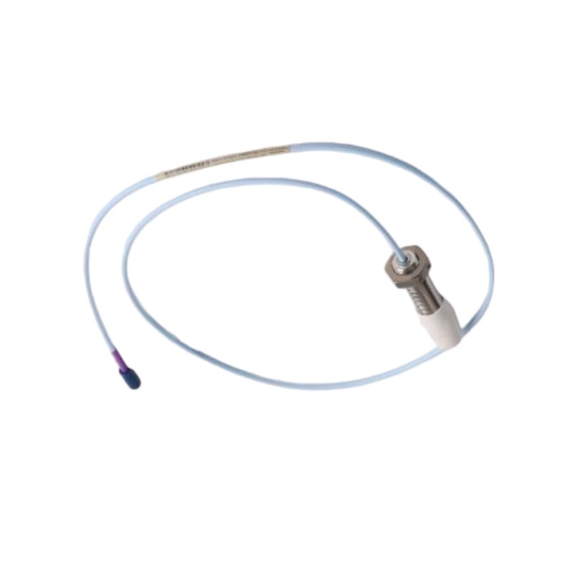
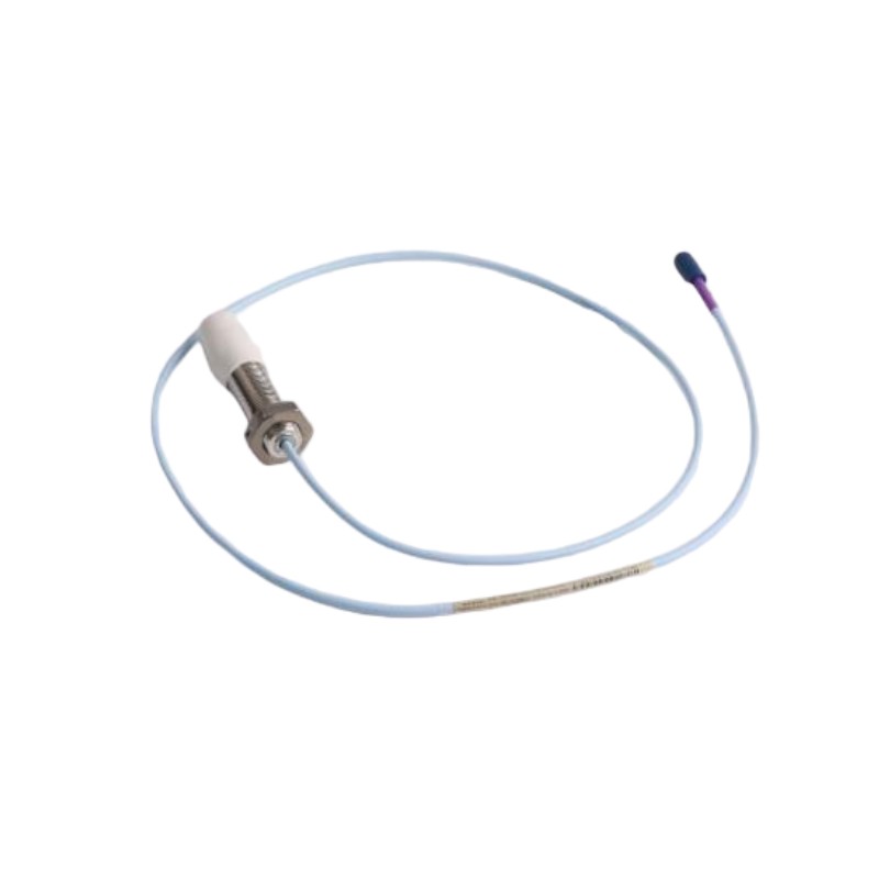
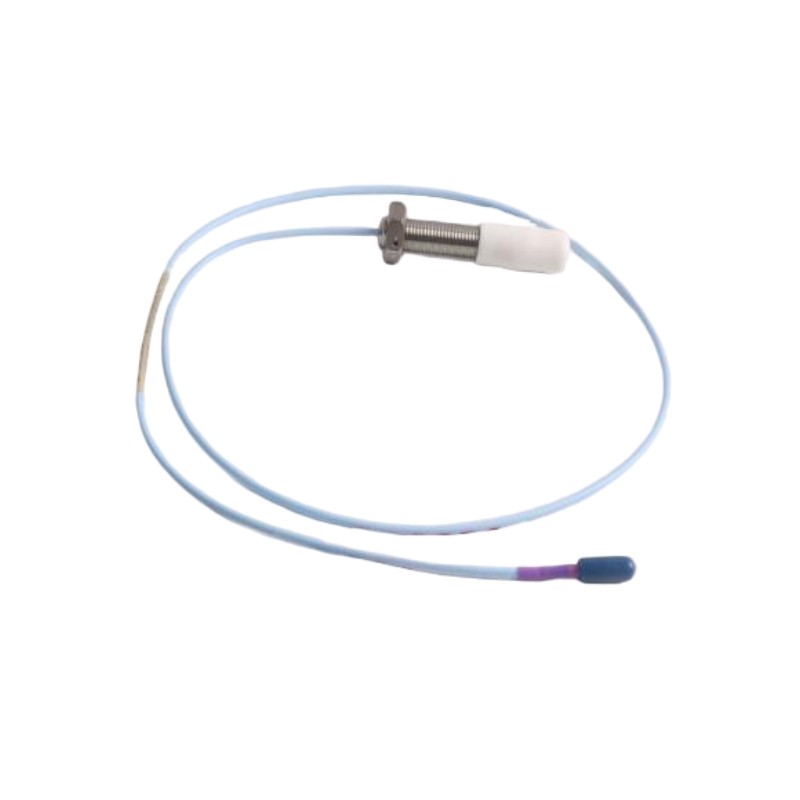
- Bently Nevada
- 330709-000-060-50-02-05
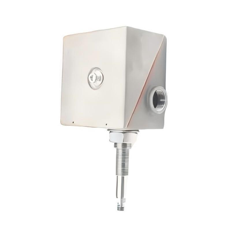
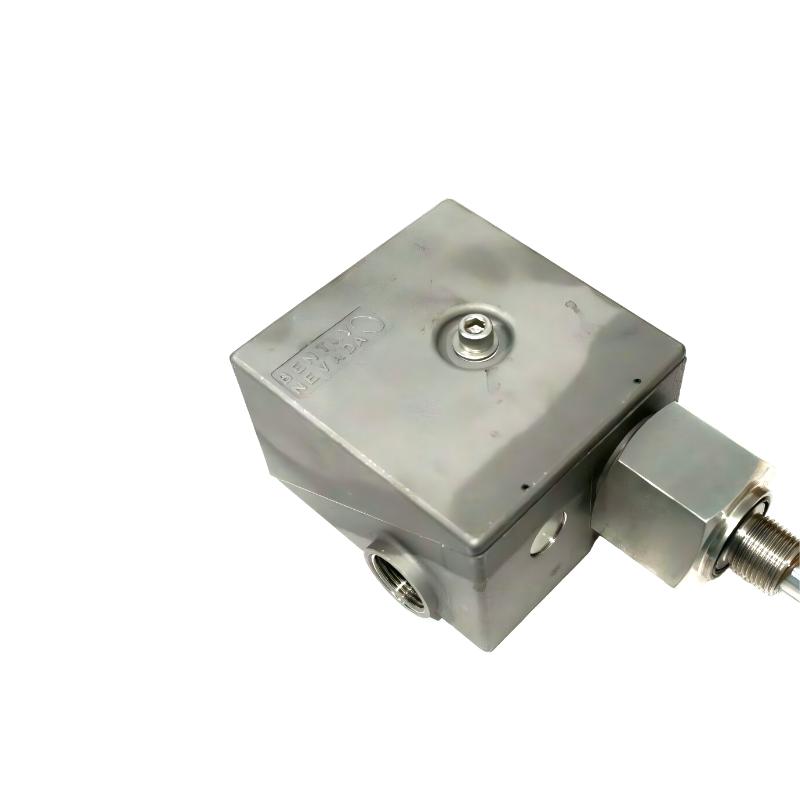
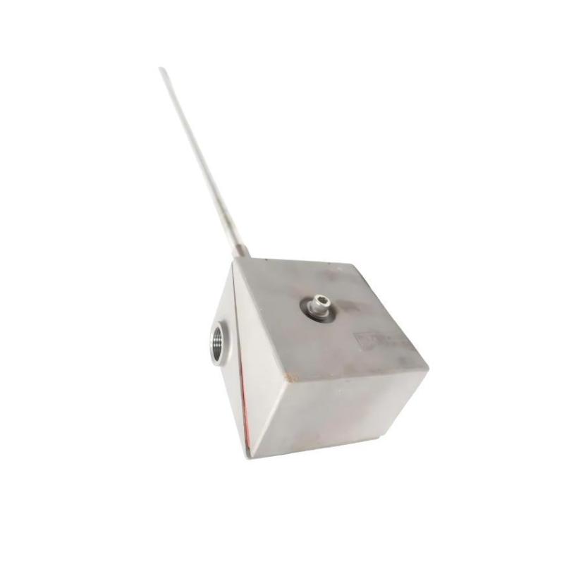
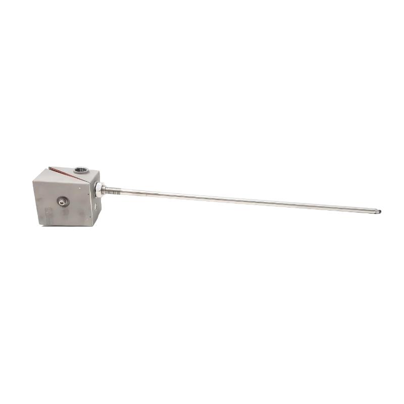
- 3300 XL 11mm Proximity Probe
- USA
- 60 mm
- 2kg
- Xiamen, China
- New & In Stock
- T/T, PayPal, Western Union
- 1 Year
- 1-3 Working Days
- DHL, UPS, TNT, FedEx and EMS.
- 24-Hour Service
- COO
- 4
Our advantage

Global Logistics
We have a 10-year logistics and express cooperation agreement, so our products can be shipped to any place in the world.

Brand new and original
Our products are imported in bulk from the place of origin. Because of the cooperative relationship, our products are all original and 100% new.

24-hour service
We provide 7*24 hours service to our customers. We will be there whenever you need us.

Price advantage
All our products are priced very favorably because we have our own warehouse and supply.
| Company Information | |||
| [email protected] | |||
| Mobile | +8615980777398 | ||
| +8615980777398 | |||
| 15980777398 |
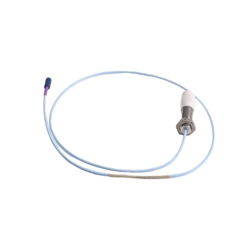
2. Detailed Product Parameters
The model number 330709-000-060-50-02-05 identifies a 3300 XL 11 mm probe with a 60 mm case-length option, a 5.0 m cable, a standard-cable ClickLoc connector, and a multiple-approval option.
The final suffix 05 is an important difference from the otherwise similar ...-02-00 model: it denotes a multiple-approval configuration. The exact certification markings and suitability for a particular hazardous area should be confirmed for the supplied unit and the installation jurisdiction.
| Parameter | Specification |
|---|---|
| Brand | Bently Nevada |
| Full model number | 330709-000-060-50-02-05 |
| Product series | 3300 XL 11 mm |
| Product type | Non-contact eddy-current proximity probe |
| Probe family diameter | 11 mm series |
| Mounting thread | M16 × 1.5 |
| Probe construction | Unarmored |
| Unthreaded length option | 000 — 0 mm |
| Overall case length option | 060 — 60 mm |
| Total cable length option | 50 — 5.0 m |
| Connector and cable option | 02 — miniature coaxial ClickLoc connector, standard cable |
| Approval option | 05 — multiple approvals |
| Nominal scale factor | 3.94 V/mm (100 mV/mil), with the specified compatible system |
| Typical linear range | Approximately 4 mm, subject to the complete system specification and target conditions |
| Probe DC resistance | Approximately 7.2 Ω ± 0.8 Ω for the 5 m configuration |
| Cable impedance | 75 Ω |
| Cable construction | Triaxial cable with FEP insulation |
| Probe-tip material | Polyphenylene sulfide (PPS) |
| Probe-case material | AISI 304 stainless steel |
| Maximum thread engagement | 24 mm |
| Minimum cable bend radius | 25.4 mm |
| Typical operating temperature range | −52°C to +177°C; observe low-temperature seal limitations |
| Minimum target diameter | Confirm against the installation and applicable technical specification |
| Measurement target | Suitable conductive shaft or machine surface |
| Main function | Shaft displacement, relative position, and vibration-related measurements |
| Required system matching | Compatible 5 m Proximitor Sensor configuration |
| Case dimension | 60 mm case-length option |
| Cable dimension | 5.0 m cable length |
| Overall installed envelope | Depends on mounting depth, connector clearance, and cable routing |
| Package dimensions | Not confirmed for this exact part number |
| Standalone weight | Exact weight not confirmed |
| Shipping weight | Exact weight not confirmed |
| Intended application | Industrial machinery condition monitoring and protection systems |
Weight and dimensions: The 60 mm case length and 5.0 m cable length are the identifiable dimensions of this configuration. An exact, verified weight for the complete probe has not been established here, so a numerical weight should not be treated as confirmed. For formal purchasing, shipping, or inventory records, use the actual unit’s technical drawing or packing documentation.
3. Model Number Breakdown
The full ordering code identifies the mechanical design, cable configuration, connector option, and approval option.
| Model section | Meaning |
|---|---|
| 330709 | 3300 XL 11 mm proximity probe, M16 × 1.5 thread, unarmored |
| 000 | 0 mm unthreaded-length option |
| 060 | 60 mm overall case-length option |
| 50 | 5.0 m total cable-length option |
| 02 | Miniature coaxial ClickLoc connector with standard cable |
| 05 | Multiple-approval configuration |
The final 05 suffix is particularly important. It identifies an approval option intended for applicable installations requiring multiple agency approvals. The precise markings and certificates must be checked against the product label and the requirements of the installation site.
The 02 connector-and-cable option should also be retained when replacing an existing probe. A FluidLoc cable version is a different configuration and should not be assumed to be identical.
4. Detailed Product Introduction
4.1 Non-contact measurement principle
The 330709 probe uses eddy-current technology to measure the gap between its sensing tip and a suitable conductive target, commonly a rotating shaft.
As the distance between the probe tip and target changes, the electrical response of the sensing system changes. Compatible transducer electronics convert that response into a usable measurement signal.
Because the probe does not need to touch the shaft during normal operation, it is suitable for continuous monitoring installations where contact-based measurement would be impractical.
4.2 3300 XL 11 mm probe design
The 3300 XL 11 mm series is designed for industrial proximity measurement applications requiring the corresponding probe geometry and measurement range.
Depending on the machine design and monitoring arrangement, this family may be used for shaft vibration, axial-position measurement, differential-expansion measurement, and other supported displacement applications.
The correct measurement function depends on the overall system configuration and installation design. A probe should not be selected solely by its physical appearance or series name.
4.3 M16 × 1.5 mounting thread
This model has an M16 × 1.5 mounting thread and an unarmored case. The threaded mounting arrangement allows the probe to be installed in a compatible holder or machine mounting point.
The 60 mm case-length option is important when checking the available installation depth. Before installation, verify the mounting thread, engagement length, probe clearance, and distance from nearby components.
The probe must remain securely mounted during operation and must not contact the rotating target.
4.4 Five-metre cable arrangement
The 5.0 m cable option gives the specified model a defined total cable length for connection to the compatible measurement electronics.
The cable should be routed to avoid sharp edges, abrasion, excessive heat, and mechanical interference. Its minimum bend radius should be observed, and the connector should be properly seated and secured according to the applicable installation procedure.
The 5 m cable is also part of the electrical configuration. The probe must be matched to the appropriate 5 m Proximitor Sensor arrangement rather than combined indiscriminately with electronics designed for a different cable length.
4.5 Multiple-approval configuration
The 05 suffix distinguishes this version from the otherwise similar model ending in 00. The multiple-approval option is intended for applicable installations requiring the relevant approval markings.
The presence of this suffix does not mean that the probe is automatically suitable for every hazardous location worldwide. The exact certificates, temperature classification, equipment marking, and installation requirements should be verified for the destination site.
4.6 Integration with monitoring equipment
The probe is a sensing component, not a standalone monitoring instrument. A typical measurement system includes the probe, compatible cable components, a Proximitor Sensor, and monitoring equipment.
The resulting signal may be used for shaft-position measurement, vibration monitoring, trend analysis, and alarm functions supported by the connected monitoring system.
Correct component matching, installation, calibration, and configuration are essential to obtaining meaningful measurements.
5. Product Applications
5.1 Steam turbines
Steam turbines may use proximity systems to monitor shaft vibration, axial position, and other machine movements specified in the monitoring design.
Measurements can help operators and maintenance personnel observe changes during start-up, changes in load, normal operation, and shutdown. The exact sensor location and measurement function depend on the turbine’s construction and monitoring requirements.
5.2 Gas turbines
Gas turbines operate under demanding mechanical and thermal conditions. Shaft-related measurements can contribute to the assessment of rotor behavior and help identify changes that warrant further investigation.
The probe should be installed only where its mechanical and environmental limits meet the requirements of the machine. The temperature rating of the complete measurement system must be considered, not just that of the probe.
5.3 Centrifugal compressors
Centrifugal compressors are used in industrial process plants, gas-processing facilities, and utility systems. Suitable proximity probes can provide shaft-position or vibration-related measurements for compatible monitoring equipment.
The resulting data can be compared with established operating trends to help maintenance teams investigate abnormal vibration, changing rotor behavior, or other machinery concerns.
5.4 Reciprocating compressors
Selected reciprocating compressor installations use proximity probes for rod-position or rod-drop measurements. Such applications require careful consideration of the measurement range, target geometry, mounting position, and the monitoring system’s configuration.
The 3300 XL 11 mm family may be relevant where the required measurement range and installation requirements are compatible with the system.
5.5 Pumps and electric motors
Large pumps and motors may require shaft-related measurements as part of a condition monitoring arrangement.
A proximity probe can provide non-contact measurements when the machine design, shaft material, mounting location, and associated electronics are suitable. The probe configuration must match the intended measurement point.
5.6 Generators and other rotating machinery
Generators and other rotating equipment may use shaft-position or vibration measurements to monitor rotor behavior.
The probe can supply measurement information to compatible electronics, allowing monitoring equipment to record changes and compare them with established operating conditions.
5.7 Industrial condition monitoring
In industrial plants, proximity measurements can contribute to condition-based maintenance programs. Trend information can help maintenance teams decide when a machine needs closer inspection.
The readings should be interpreted alongside machine speed, load, bearing conditions, temperature, and other relevant operating information. A probe measurement by itself does not identify every possible mechanical fault.
6. Product Advantages
6.1 Non-contact sensing
The probe measures the position of a suitable conductive target without requiring physical contact during normal operation. This avoids the contact wear associated with mechanical sensing devices and makes the technology suitable for rotating machinery.
6.2 Defined mechanical dimensions
The M16 × 1.5 mounting thread and 60 mm case-length option provide clear mechanical identifiers for installation planning and replacement selection.
These details help engineers compare the replacement probe with the existing installation and check whether the mounting point and available clearance are suitable.
6.3 Five-metre cable configuration
The 5.0 m cable option provides a defined connection length for installations requiring the associated electronics to be positioned away from the probe.
Maintaining the correct cable length and matching it with compatible system electronics helps preserve the intended measurement configuration.
6.4 Integration with industrial monitoring systems
The probe is designed to operate within a compatible proximity measurement system. This allows it to contribute to continuous monitoring, measurement trending, and machinery protection functions supported by the connected equipment.
6.5 Suitable for a range of rotating machinery
The 3300 XL 11 mm family can be used in several types of industrial machinery where the measurement requirements are appropriate. This includes selected turbine, compressor, and other rotating-equipment applications.
The suitability of an individual probe depends on the machine design, required measurement function, target material, mounting configuration, and environmental conditions.
6.6 Easier spare-parts identification
The complete model number identifies the selected case length, cable length, connector type, and approval option.
Recording the complete part number in a maintenance database helps prevent ordering errors, especially where several probes from the same family are installed on one machine.
6.7 Approval option for applicable installations
The multiple-approval configuration can be relevant where the installation requires the appropriate agency markings. This helps procurement personnel identify the intended approval variant.
The actual approval documents and product markings should still be checked before installation in a regulated or hazardous area.
7. Five Recommended Models from the Same Series or Related Configurations
The following options are useful for comparing case lengths, connector and cable configurations, and mounting arrangements within the same product family. They are not all direct replacements for the specified model.
| No. | Model | Main parameters | Dimensions | Weight (kg) |
|---|---|---|---|---|
| 1 | 330709-000-040-50-02-05 | 3300 XL 11 mm; M16 × 1.5 thread; unarmored; 40 mm case; 5 m standard cable; multiple approvals | 40 mm case; 5.0 m cable | Exact weight not confirmed |
| 2 | 330709-000-050-50-02-05 | 3300 XL 11 mm; M16 × 1.5 thread; unarmored; 50 mm case; 5 m standard cable; multiple approvals | 50 mm case; 5.0 m cable | Exact weight not confirmed |
| 3 | 330709-000-060-50-02-00 | Same general probe configuration; 60 mm case; 5 m standard cable; no-approval option | 60 mm case; 5.0 m cable | Exact weight not confirmed |
| 4 | 330709-000-060-50-12-05 | M16 × 1.5 thread; unarmored; 60 mm case; 5 m FluidLoc cable; miniature coaxial ClickLoc connector; multiple approvals | 60 mm case; 5.0 m cable | Exact weight not confirmed |
| 5 | 330710-000-060-50-02-05 | Related 3300 XL 11 mm armored probe configuration; 60 mm case; 5 m standard cable; multiple approvals | 60 mm case; 5.0 m cable; armored construction changes the external envelope | Exact weight not confirmed |
Model selection guidance
330709-000-040-50-02-05 has a shorter case than the main model. It may suit an installation designed for a 40 mm case, but it should not be substituted without checking the required mounting depth and probe clearance.
330709-000-050-50-02-05 uses a 50 mm case. It is another comparison option when the installation has a different required case length.
330709-000-060-50-02-00 has the same general mechanical and cable configuration but a different approval suffix. Confirm the required approval markings before choosing it.
330709-000-060-50-12-05 uses the FluidLoc cable configuration rather than the standard cable option. The cable type and connector arrangement must match the installation requirements.
330710-000-060-50-02-05 is an armored related model. Armor may provide additional mechanical protection in suitable installations, but the external dimensions and installation clearances differ from the unarmored version.
The complete part number, cable type, mounting thread, case length, and approval requirements should be checked before purchasing any alternative.
8. Five Recommended Models from the Same Brand
The following models cover related sensing and monitoring functions. Some are components of the same measurement system, while others are monitoring equipment rather than direct probe replacements.
| No. | Model | Product category | Main parameters and function | Dimensions | Weight (kg) |
|---|---|---|---|---|---|
| 1 | 330180-50-00 | Proximitor Sensor | Associated electronics for a compatible proximity system; match to the probe and cable configuration | Housing dimensions depend on the applicable drawing | Exact weight not confirmed |
| 2 | 330130-040-00-00 | Extension cable | Extension cable for compatible proximity transducer components; verify connector and electrical configuration | Confirm exact cable length and connector envelope | Exact weight not confirmed |
| 3 | 330101-00-08-10-02-00 | 3300 XL 8 mm proximity probe configuration | Related non-contact shaft measurement product; confirm complete configuration and system compatibility | Model-specific; drawing required | Exact weight not confirmed |
| 4 | 3500/42M | Machinery monitoring module | Four-channel Proximitor / Seismic Monitor family for supported measurement inputs | Module and rack dimensions depend on the system configuration | Exact weight not confirmed |
| 5 | 3500/22M | Rack interface module | Interface module for a compatible 3500 monitoring system; supports communication and rack data functions according to configuration | Rack-module dimensions; verify applicable drawing | Exact weight not confirmed |
8.1 330180-50-00 — Proximitor Sensor
The Proximitor Sensor is the associated electronics component used with a compatible proximity probe and cable arrangement. It provides the required interface between the probe and the monitoring equipment.
When selecting it for the 330709 probe, verify the cable-length configuration and the complete system requirements. The 5 m probe should be used with the corresponding compatible 5 m Proximitor Sensor arrangement.
8.2 330130-040-00-00 — Extension Cable
An extension cable is used to connect compatible transducer components when the installation requires a specific distance between the probe and associated electronics.
Cable length, connector type, and electrical characteristics must match the intended measurement system. The exact cable specification should be checked before ordering.
8.3 330101-00-08-10-02-00 — 8 mm Proximity Probe Configuration
The 3300 XL 8 mm family provides a related option for non-contact shaft measurement. It is relevant when the machine design and measurement requirements call for an 8 mm probe system.
The 8 mm and 11 mm families have different geometries and system characteristics. This model should not be treated as a direct replacement for the 11 mm probe without engineering verification.
8.4 3500/42M — Machinery Monitoring Module
The 3500/42M is a monitoring module intended for compatible machinery monitoring systems. It processes supported measurement inputs and performs monitoring functions according to the installed system configuration.
It serves a different role from the 330709 probe. The probe measures the target, while the monitoring module handles compatible input signals as part of the overall monitoring arrangement.
8.5 3500/22M — Rack Interface Module
The 3500/22M is an interface module used in compatible monitoring racks. It supports communication and access to rack information according to the configured system.
It is not a sensing probe and cannot replace the 330709 directly. It may be relevant when maintaining or expanding the monitoring infrastructure that receives measurements from compatible sensors.
9. Main Product and Related Equipment Comparison
| Feature | 330709-000-060-50-02-05 | 330180-50-00 | 330130-040-00-00 | 3500/42M |
|---|---|---|---|---|
| Product type | Proximity probe | Proximitor Sensor | Extension cable | Monitoring module |
| Primary function | Measure shaft displacement and relative position | Provide associated proximity-system electronics | Connect compatible transducer components | Monitor supported measurement inputs |
| Sensing tip | Yes | No | No | No |
| Cable configuration | 5 m probe cable | Depends on configuration | Cable component | Not its primary function |
| Threaded probe mounting | M16 × 1.5 | Not applicable | Not applicable | Rack/module mounting |
| Typical installation | Near the target shaft | Suitable protected location | Between compatible system components | Compatible monitoring rack |
| Direct replacement for the probe | Main product | No | No | No |
| Dimensions | 60 mm case; 5 m cable | Confirm housing drawing | Confirm cable drawing | Confirm module and rack drawing |
| Weight (kg) | Exact weight not confirmed | Exact weight not confirmed | Exact weight not confirmed | Exact weight not confirmed |
10. Installation and Maintenance Recommendations
Before installing or replacing the probe, check the following items.
1. Confirm the complete part number. Verify the case length, cable length, connector configuration, and approval suffix.
2. Check the mounting thread. Confirm that the installation uses M16 × 1.5.
3. Verify the case length. Ensure that the 60 mm case fits the mounting point and available clearance.
4. Confirm the cable length. Verify that the system requires the 5.0 m cable configuration.
5. Check the connector. Confirm that the miniature coaxial ClickLoc connector and standard cable match the existing system.
6. Match the associated electronics. Use the compatible 5 m Proximitor Sensor configuration and any required system components.
7. Verify approval markings. Confirm that the 05 configuration meets the installation’s applicable certification and hazardous-area requirements.
8. Set the probe gap correctly. Follow the applicable installation and calibration procedure.
9. Check the target surface. Confirm that the target material and geometry are suitable for the intended measurement.
10. Secure the probe. Ensure that it remains mechanically stable and cannot contact the shaft during normal operation.
11. Protect the cable. Avoid sharp edges, excessive heat, abrasion, and moving parts. Observe the specified bend radius.
12. Record commissioning details. Keep the complete model number, installation point, system configuration, and baseline readings in the maintenance records.
13. Verify physical data. Use the exact technical drawing and actual shipment documentation for final dimensions, standalone weight, and package weight.
11. Final Product Summary
The Bently Nevada 330709-000-060-50-02-05 is a 3300 XL 11 mm non-contact proximity probe with an M16 × 1.5 mounting thread, unarmored construction, 60 mm case-length option, 5.0 m standard cable, and miniature coaxial ClickLoc connector. The final 05 suffix identifies the multiple-approval configuration.
Its primary function is to provide shaft-position and displacement measurements as part of a compatible machinery monitoring system. Suitable applications include selected turbine, compressor, reciprocating machinery, pump, motor, and generator installations.
The principal advantages are non-contact measurement, a defined mechanical configuration, integration with compatible monitoring equipment, and a specified cable and connector arrangement. Correct system matching and installation are essential to obtain reliable measurements.
For purchasing and maintenance purposes, the key confirmed configuration dimensions are the 60 mm case length and 5.0 m cable length. The exact standalone weight and package dimensions have not been confirmed, so these values should be taken from the actual product drawing or shipment documentation before being entered into formal engineering or inventory records.