
NewsNEWCENTER
Featured products
Contact Us
GE 1719-0023 Analog Main Board Installation Guide
2026-10-13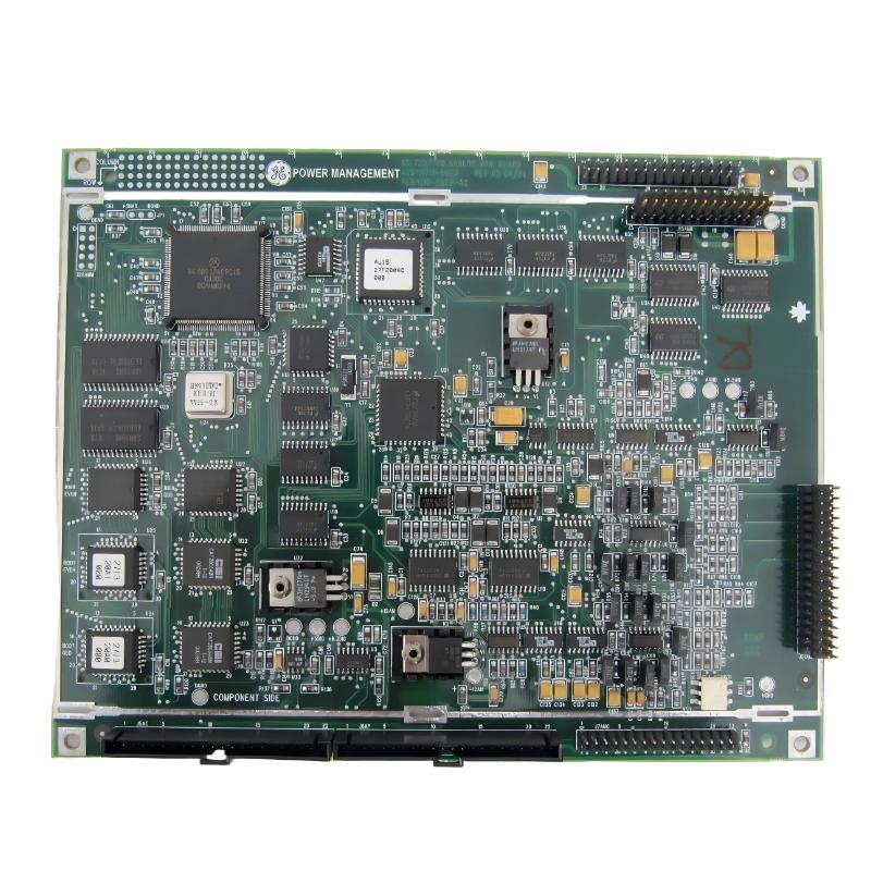
The GE 1719-0023 Analog Main Board is an industrial electronic circuit board intended for use within a compatible control or automation system. Correct installation requires verification of the complete model number, board revision, connector arrangement, system compatibility, and applicable electrical requirements. This GE 1719-0023 Analog Main Board installation guide explains practical preparation, handling, installation, system integration, commissioning, and initial troubleshooting procedures for maintenance engineers and industrial control technicians.
1. GE 1719-0023 Analog Main Board Overview
An analog main board may support analog signal processing, signal conditioning, internal control-system communication, or related electronic functions, depending on its specific design. The precise role of the GE 1719-0023 must be confirmed against the documentation for the equipment in which it is installed. Its exact channel configuration, signal ranges, terminal assignments, and electrical ratings should not be assumed from the model number alone.
Before installation, identify the equipment cabinet, rack, or assembly where the existing board operates. Compare the replacement board with the installed unit and confirm that the part number and hardware revision are suitable for the target system.
2. GE 1719-0023 Installation Preparation
2.1 Verify the Part Number and Compatibility
- Confirm that the board is marked GE 1719-0023.
- Record any available revision, assembly, or serial identification.
- Check compatibility with the host equipment, backplane, connectors, and system configuration.
- Verify whether the application requires configuration files, calibration data, jumpers, or software settings to be retained.
- Inspect the existing installation for modifications or nonstandard wiring.
2.2 Prepare the Work Area
Use an approved maintenance procedure before opening the cabinet. Isolate all relevant power sources, apply lockout/tagout procedures, and verify the absence of hazardous voltage using suitable test equipment. Industrial control cabinets may contain multiple supplies or stored electrical energy even after the primary source has been switched off.
Use appropriate electrostatic discharge protection when handling the circuit board. Work on a clean, dry, static-controlled surface, and avoid touching exposed contacts or electronic components.
2.3 Inspect the Replacement Board
- Check for cracked components, damaged connectors, bent contacts, corrosion, or contamination.
- Look for signs of overheating, such as discoloration or damaged insulation.
- Compare the connector positions and mounting points with the original board.
- Confirm that packaging and handling have not caused visible mechanical damage.
3. GE 1719-0023 Analog Main Board Installation Procedure
3.1 Document the Existing Configuration
Before removing the existing board, photograph its installed position and record connector locations, cable labels, board orientation, and any accessible configuration settings. Label removable connections individually so that each cable can be returned to the correct position.
3.2 Remove the Existing Board
- Confirm that the equipment has been placed in a safe maintenance state.
- Verify isolation and allow any specified discharge interval to elapse.
- Release retaining clips, screws, or locking mechanisms according to the equipment design.
- Disconnect cables only after confirming that they are de-energized and that removal is permitted by the system procedure.
- Withdraw the board evenly without twisting it or applying force to the connectors.
If the existing board is stuck, do not pry against sensitive components or connector housings. Check for overlooked fasteners, retainers, or locking mechanisms.
3.3 Install the GE 1719-0023 Board
- Compare the replacement board with the removed unit one final time.
- Align the board with the designated guides, connector, or mounting points.
- Insert it evenly and ensure that the connectors are properly seated.
- Secure all required retainers and fasteners using the equipment’s specified procedure.
- Reconnect labeled cables and verify that each connection matches the approved wiring arrangement.
- Check that no cable is pinched and that the board is not under mechanical stress.
Do not force a connector into place. If the board does not align naturally, stop and check the part number, orientation, connector keying, and mounting arrangement.
4. GE 1719-0023 Wiring and System Integration
The exact electrical interfaces of the GE 1719-0023 should be confirmed using the applicable equipment documentation. Do not infer pin assignments, supply voltages, analog input ranges, output types, or communication interfaces from the product name alone.
A representative control-system relationship may be illustrated as follows:
Field Devices / Signal Sources
            |
            v
Approved Input or Interface Connections
            |
            v
GE 1719-0023 Analog Main Board
            |
            v
Host Control Electronics
            |
            v
Controller Logic / Monitoring / Operator Interface
This diagram is illustrative rather than a verified wiring diagram for the specific board. Actual signal flow depends on the equipment in which the board is installed.
4.1 Verify Connections Before Power-Up
- Check connector seating and cable identification.
- Confirm supply and ground connections against the correct technical documentation.
- Inspect for loose strands, bent contacts, and accidental shorts.
- Verify shielding and grounding practices required by the host system.
- Ensure that any field wiring connected to the assembly uses the approved signal type and electrical range.
4.2 Review Configuration Requirements
Some control assemblies require board identification, software configuration, calibration, or channel mapping after a replacement. Determine whether the host system automatically recognizes the board or requires a maintenance tool or engineering workstation. Preserve the original configuration where required and follow the approved restoration procedure.
5. GE 1719-0023 Commissioning and Functional Checks
5.1 Pre-Energization Inspection
Before restoring power, verify that the board is secured, all required covers and barriers are in place, tools have been removed, and personnel are clear of hazardous equipment. Confirm that the system is in a safe state for testing.
5.2 Controlled Power-Up
- Restore power according to the host equipment’s approved startup procedure.
- Observe available status indicators and system diagnostic messages.
- Check for unexpected alarms, abnormal heating, odor, smoke, or unusual electrical noise.
- Verify that the host system recognizes the installed assembly where this function is supported.
- Confirm that associated signals or functions behave as expected under controlled test conditions.
If abnormal behavior appears, stop the test and isolate the equipment according to site safety procedures. Do not repeatedly cycle power to a board showing signs of electrical damage.
5.3 Functional Validation
Functional testing should use approved test points, known-good signal sources, and the test procedures specified for the host system. Compare observed behavior with expected values and system diagnostics. Do not apply an arbitrary voltage or current to an unidentified connector.
6. Common GE 1719-0023 Installation Problems
- Board not recognized: Check seating, connector condition, part-number compatibility, and system configuration.
- Unexpected signal readings: Verify the external signal source, wiring, grounding, channel mapping, and applicable calibration settings.
- Intermittent operation: Inspect connectors, retention hardware, cable strain, contamination, and signs of heat damage.
- Startup alarms: Review the host system’s diagnostic messages and confirm that all required assemblies and settings are present.
- No visible status indication: First determine whether the board is designed to provide a visible indicator; not every board has one.
7. GE 1719-0023 Installation Maintenance Recommendations
Maintain a record of the installed part number, revision, equipment location, replacement date, configuration changes, and commissioning results. Periodically inspect the surrounding cabinet for dust accumulation, loose connectors, excessive temperature, moisture, and vibration.
Keep a known-good replacement board in suitable protective packaging when the system’s maintenance strategy requires spare inventory. Store electronic assemblies in a clean, dry environment with appropriate electrostatic protection.
8. GE 1719-0023 Analog Main Board Installation FAQs
What should be checked before installing the GE 1719-0023?
Confirm the full part number, hardware revision, host-system compatibility, connector arrangement, electrical requirements, and any configuration or calibration requirements.
Can the GE 1719-0023 be replaced while the system is powered?
Do not assume that live replacement is supported. Follow the host equipment’s approved maintenance procedure and isolate power unless the system documentation explicitly permits a qualified hot-swap procedure.
Does the GE 1719-0023 require calibration after replacement?
That depends on its design and the host system. Check the applicable technical documentation to determine whether calibration, configuration restoration, or functional verification is required.
What should be done if the board is not recognized after installation?
Check correct seating, connector condition, model and revision compatibility, host-system settings, and diagnostic messages. If the problem persists, investigate the board and the host interface using an approved maintenance procedure.
9. GE 1719-0023 Analog Main Board Technical Summary
Reliable installation of the GE 1719-0023 Analog Main Board depends on correct part identification, electrostatic protection, safe power isolation, careful connector handling, verified system compatibility, and controlled commissioning. Because exact electrical specifications and interface assignments must be established from the applicable equipment documentation, engineers should avoid assumptions based solely on the model number. A documented installation and functional test help reduce wiring errors, startup faults, and avoidable control-system downtime.